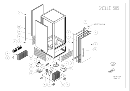
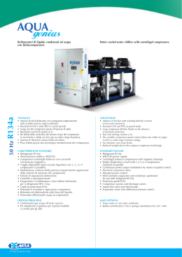
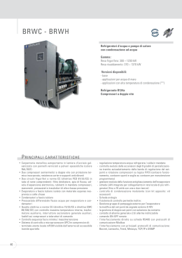
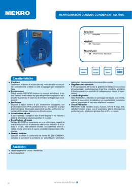
CWA/C 12 ÷ 58
refrigeratori d’acqua
water chillers
Refrigeratori d’acqua monoblocco con
condensazione ad aria e ventilatori centrifughi.
Serie a compressori ermetici.
Packaged water chillers, air cooled with
centrifugal fans. Units equipped with reciprocating
hermetic compressors.
K11030
ed. 9.
caratteristiche tecniche
technical features
MODELLO
MODEL
Dati tecnici
Technical data
Potenzialità frigorifera nominale (*)
Nominal cooling capacity (*)
Pressione sonora (**)
Sound pressure level (**)
Compressore alternativo/gradini
Reciprocating compressor/steps
Circuiti
Circuits
Ventilatori
Fans
Portata nominale ventilatori
Fan nominal air flow
Prevalenza statica utile nominale (***)
Nominal E.S.P. (***)
Numero di giri nominale
Rated RPMs
Prevalenza statica utile massima (***)
Max E.S.P. (***)
Numero di giri massimo
Max RPMs
Portata nominale evaporatore
Evaporator nominal water flow
Perdite di carico nominali evaporatore
Evaporator nominal pressure drops
Contenuto acqua evaporatore
Evaporator water contents
Carica refrigerante R 22
R 22 refrigerant charge
Carica olio SHELL FRIGO 2788
SHELL FRIGO 2788 oil charge
Dati elettrici
Electrical data
Potenza assorbita totale (*)
Total absorbed power (*)
Alimentazione elettrica di potenza
Power supply
Alimentazione elettrica ausiliaria
Auxiliary power supply
Corrente nominale
Nominal current
Corrente massima
Max. current
Corrente di spunto
Starting current
kW
dB(A)
19
13,95
22,33
32
38
n.
1
1
n.
1
1
1 x 1,1
1 x 1,5
6.000
9.000
n. x kW
m3/h
Pa
giri/min. / r.p.m.
Pa
giri/min. / r.p.m.
l/h
kPa
25
30
700
600
70
100
770
700
2.400
3.840
25
38
l
4,7
6,3
kg
3,6
6,9
l
2,0
3,2
5,90
8,40
V-ph-Hz
400-3-50
400-3-50
V-ph-Hz
230-1-50
230-1-50
A
11,3
16,0
A
13,7
19,5
A
66,0
82,0
kW
(*) Alle seguenti condizioni: temperatura aria
ingresso condensatore 32°C; temperatura
acqua refrigerata 7°C; differenziale di
temperatura all’evaporatore 5°C; prevalenza
statica utile massima.
(**) Livello di pressione sonora in dB(A) riferito
a una misura in campo aperto alla distanza di
5 m dall’unità funzionante alle condizioni
nominali con una canalizzazione di 3 m posta
sulla mandata del ventilatore.
(***) La prevalenza utile desiderata è
ottenibile agendo sulla puleggia variabile
installata sul motore del ventilatore; la
prevalenza utile massima si ottiene con
3 giri di svitamento della puleggia variabile,
partendo dalla posizione di puleggia chiusa.
2
12
(*) At the following conditions: inlet air
temperature at the condenser 32°C; chilled
water temperature 7°C; water ∆t at the
evaporator 5°C; maximum external static
pressure.
(**) Sound pressure level in dB(A) referred to
open-field measurement at a distance of 5 m.
from unit running at rated conditions with 3 m.
ducts placed at fan outlet.
(***) Desired static head may be obtained by
using the variable pulley installed on the fan
motor; maximum static head is obtained by
loosening the variable pulley by three turns,
beginning from the closed pulley position.
caratteristiche geometriche e di installazione
overall dimensions and service spaces
CWA/C 12-19
Installazione
i
m
p
n1
o
● L’unità è provvista di attacchi idraulici
filettati maschio.
● L’unità va posizionata rispettando gli spazi
tecnici minimi raccomandati in figura n. 1,
tenendo presente l’accessibilità alle
connessioni acqua ed elettriche.
● L’unità può essere dotata di supporti
antivibranti forniti a richiesta (KSA).
D4
n2
q
3
s
l
S5
D1
5
9
D2
4
Nota Bene
2
c
● La movimentazione dell’unità deve essere
eseguita con cura onde evitare danni alla
struttura esterna e alle parti meccaniche ed
elettriche interne (fig. 2).
1
h
D3
7
g
8
6
Installation
t
u
e
S1
d
t
v
f
b
S2
w
v
a
S3
r
S4
fig. 1
1. Evaporatore
2. Compressore
3. Condensatore
4. Quadro elettrico
5. Ventilatore
6. Entrata acqua all’evaporatore
7. Uscita acqua dall’evaporatore
8. Alimentazione elettrica
9. Motore elettrico
MODELLO
MODEL
Dimensioni
Dimensions
a
b
c
d
e
f
g
h
i
l
m
n1
n2
o
p
q
r
s
t
u
v
w
D1
D2
D3
D4
S1
S2
S3
S4
S5
Attacchi acqua
Water connections
Peso (*)
Weight (*)
mm
mm
mm
mm
mm
mm
mm
mm
mm
mm
mm
mm
mm
mm
mm
mm
mm
mm
mm
mm
mm
mm
mm
mm
mm
mm
mm
mm
mm
mm
mm
kg
1. Evaporator
2. Compressor
3. Condenser
4. Electrical board
5. Fan
6. Water inlet into the evaporator
7. Water outlet from the evaporator
8. Power input
9. Electrical motor
● The unit is provided with hydraulic threaded
male connections.
● The unit must be positioned according to the
minimal service spaces indicated in picture 1,
taking access to plumbing and electrical
connections into account.
● The unit may be equipped with antivibration
mountings, available on request (KSA).
N.B.:
Handle the unit with care to avoid damaging
the external structure as well as internal
mechanical and electric parts (picture 2)
12
19
970
780
1.135
365
260
155
160
140
346
396
38
400
266
304
35
32
41
698
52
866
868
750
350
70
350
700
500
700
600
1.170
840
1.295
395
305
140
125
150
346
456
38
315
315
230
136
174
35
32
41
758
52
1.066
1.068
925
325
70
400
700
500
700
600
1 1/2 G
2G
200
295
fig. 2
(*) Il peso dell’unità è riferito alla macchina
completamente accessoriata.
(*) The weight of the unit refers to a fully
accessoried machine.
3
caratteristiche tecniche
technical features
MODELLO
MODEL
Dati tecnici
Technical data
Potenzialità frigorifera nominale (*)
Nominal cooling capacity (*)
Pressione sonora (**)
Sound pressure level (**)
Compressore alternativo/gradini
Reciprocating compressor/steps
Circuiti
Circuits
Ventilatori
Fans
Portata nominale ventilatori
Fan nominal air flow
Prevalenza statica utile nominale (***)
Nominal E.S.P. (***)
Numero di giri nominale
Rated RPMs
Prevalenza statica utile massima (***)
Max E.S.P. (***)
Numero di giri massimo
Max RPMs
Portata nominale evaporatore
Evaporator nominal water flow
Perdite di carico nominali evaporatore
Evaporator nominal pressure drops
Contenuto acqua evaporatore
Evaporator water contents
Carica refrigerante R 22
R 22 refrigerant charge
Carica olio SHELL FRIGO 2788
SHELL FRIGO 2788 oil charge
Dati elettrici
Electrical data
Potenza assorbita totale (*)
Total absorbed power (*)
Alimentazione elettrica di potenza
Power supply
Alimentazione elettrica ausiliaria
Auxiliary power supply
Corrente nominale
Nominal current
Corrente massima
Max. current
Corrente di spunto
Starting current
kW
dB(A)
29
38
47
58
27,44
33,72
44,07
54,65
67,44
42
43
43
44
44
n.
1
1
2
2
2
n.
1
1
2
2
2
n. x kW
1 x 2,2
1 x 3,0
1 x 3,0
1 x 4,0
1 x 5,5
m3/h
10.200
15.750
15.400
18.550
18.400
Pa
giri/min. / r.p.m.
35
45
35
40
25
650
630
630
650
700
Pa
100
90
100
90
75
giri/min. / r.p.m.
700
690
690
700
750
4.720
5.800
7.580
9.400
11.600
32
35
27
37
35
l/h
kPa
l
14,1
18,1
24,1
31,4
37,5
kg
8,0
8,5
13,5
17,0
18,0
l
4,0
4,8
6,5
6,5
9,6
11,40
14,60
16,80
22,20
28,70
V-ph-Hz
400-3-50
400-3-50
400-3-50
400-3-50
400-3-50
V-ph-Hz
230-1-50
230-1-50
230-1-50
230-1-50
230-1-50
A
20,4
26,0
32,0
39,5
52,0
A
24,2
31,5
38,4
47,1
61,4
A
111,0
137,0
102,0
134,0
167,0
kW
(*) Alle seguenti condizioni: temperatura aria
ingresso condensatore 32°C; temperatura
acqua refrigerata 7°C; differenziale di
temperatura all’evaporatore 5°C; prevalenza
statica utile massima.
(**) Livello di pressione sonora in dB(A) riferito
a una misura in campo aperto alla distanza di
5 m dall’unità funzionante alle condizioni
nominali con una canalizzazione di 3 m posta
sulla mandata del ventilatore.
(***) La prevalenza utile desiderata è
ottenibile agendo sulla puleggia variabile
installata sul motore del ventilatore; la
prevalenza utile massima si ottiene con
3 giri di svitamento della puleggia variabile,
partendo dalla posizione di puleggia chiusa.
4
24
(*) At the following conditions: inlet air
temperature at the condenser 32°C; chilled
water temperature 7°C; water ∆t at the
evaporator 5°C; maximum external static
pressure.
(**) Sound pressure level in dB(A) referred to
open-field measurement at a distance of 5 m.
from unit running at rated conditions with 3 m.
ducts placed at fan outlet.
(***) Desired static head may be obtained by
using the variable pulley installed on the fan
motor; maximum static head is obtained by
loosening the variable pulley by three turns,
beginning from the closed pulley position.
caratteristiche geometriche e di installazione
overall dimensions and service spaces
CWA/C 24-29-38-47-58
i
y
S5
h
r
D3
p
D1
n
D4
o
q
n
l
s
s
5
i
4
9
8
2
6
1
m
D2
c
3
7
100
g
e
f
d
a
u
b
t
S1
t
S3
S2
v
w
x
z
v
S4
fig. 3
1. Evaporatore
2. Compressore
3. Condensatore
4. Quadro elettrico
5. Ventilatore
6. Entrata acqua all’evaporatore
7. Uscita acqua dall’evaporatore
8. Alimentazione elettrica
9. Motore elettrico
MODELLO
MODEL
Dimensioni
Dimensions
a
mm
b
mm
c
mm
d
mm
e
mm
f
mm
g
mm
h
mm
i
mm
l
mm
m
mm
n
mm
o
mm
p
mm
q
mm
r
mm
s
mm
t
mm
u
mm
v
mm
w
mm
x
mm
y
mm
z
mm
D1
mm
D2
mm
D3
mm
D4
mm
S1
mm
S2
mm
S3
mm
S4
mm
S5
mm
Attacchi acqua
Water connections
Peso (*)
kg
Weight (*)
Installation
1. Evaporator
2. Compressor
3. Condenser
4. Electrical board
5. Fan
6. Water inlet into the evaporator
7. Water outlet from the evaporator
8. Power input
9. Electrical motor
● Les unités 24 ÷ 38 sont équipées de raccords
hydrauliques filetés mâle; les unités 47 ÷ 58 sont
équipées de raccords hydrauliques bridés.
● L’unité doit être positionnée en respectant les
espaces techniques minimums indiqués en fig.3
et en veillant à garantir l’accès aux
raccordements eau et électriques.
● L’unité peut être livrée équipée d’une sortie
d’air supérieure (USC).
● L’unité peut être équipée de supports
antivibratiles fournis sur demande (KSA).
24
29
38
47
58
1.640
780
1.500
1.025
395
220
265
366
347
66
1.087
402
308
177
351
110
20
41
698
53
767
767
67
1.325
860
143
172
800
800
500
700
600
1.890
780
1.735
1.375
335
180
280
304
409
66
1.260
479
375
187
370
125
20
41
698
53
487
810
67
487
1.610
1.060
140
140
1.000
800
500
700
600
1.890
780
1.735
1.200
420
270
280
304
409
66
1.260
479
375
187
370
125
20
41
698
53
487
810
67
487
1.610
1.060
140
140
1.000
800
500
700
800
2.050
780
1.735
1.525
325
200
280
309
409
66
1.260
479
375
204
511
105
20
41
698
54
647
648
62
647
1.876
1.060
34
140
1.200
900
600
700
1.000
2.050
780
1.735
1.475
325
250
280
309
409
66
1.260
479
375
204
511
105
20
41
698
54
647
648
62
647
1.876
1.060
34
140
1.200
900
600
700
1.000
1 1/2 G
1 1/2 G
1 1/2 G
DN 50
DN 50
380
480
570
685
710
Manutention
(*) Il peso dell’unità è riferito alla macchina
completamente accessoriata.
(*) The weight of the unit refers to a fully
accessoried machine.
La manutention de l’unité doit être effectuée
avec précaution, afin d’éviter d’endommager la
structure extérieure et les parties mécaniques
et électriques (fig.4).
fig. 4
Installation
● Die Wasseranschlüsse der Modelle 24 ÷ 38
sind als Außengewinde ausgeführt, die Modelle
47 ÷ 58 sind mit Flanschanschlüssen versehen.
● Bei der Aufstellung vorgeschriebenen
Mindestabstände (Abb. 3) einhalten. Dazu sind
ebenfalls die Freibereiche für den Zugriff auf die
Wasser- und Stromanschlüsse zu berücksichtigen.
● Die Maschine ist ebenfalls mit oberhalb
angeordneter Luftaustrittsöffnung (USC) lieferbar.
● Die Maschine kann mit auf Anfrage lieferbare
Schwingungsdämpfer (KSA) versehen werden.
Versetzen/Befördern
● Versetzen und Befördern der Maschine
müssen sorgsam ausgeführt werden, um deren
Tragrahmen und Verkleidung sowie die innen
befindlichen mechanischen und elektrischen
Komponenten nicht zu beschädigen (Abb. 4).
5
schemi circuiti frigoriferi e idraulici
refrigerant and hydraulic circuits diagrams
CWA/C 12-19
CEB = Condensatore a batteria alettata
CPS = Compressore alternativo
ECH = Evaporatore a tubi coassiali per i
modelli 12 e 19; a fascio tubiero per i
modelli 24 ÷ 58
FT = Filtro
LUE = Indicatore liquido-umidità
PA = Pressostato di alta pressione a riarmo
automatico
PB = Pressostato di bassa pressione a
riarmo automatico
RC = Resistenza carter compressore
RE = Resistenza evaporatore
TA = Termostato antigelo
TL = Termostato di lavoro
VL = Ventilatore
VTE = Valvola termostatica
CEB
PA
PB
VL
CPS
T TL
ECH
RC
LUE
FT
RE
VTE
T TA
fig. 5
CWA/C 24-29
CEB
CEB = Finned condenser coil
CPS = Reciprocating compressor
ECH = Evaporator with coaxial tubes for
models 12 and 19; with tube bundle
for models 24 - 58
FT = Filter
LUE = Liquid/humidity indicator
PA = Automatic reset H.P. switch
PB = Automatic reset L.P. switch
RC = Compressor crankcase heater
RE = Evaporator heater
TA = Antifreeze thermostat
TL = Control thermostat
VL = Fan
VTE = Thermostatic valve
PA
PB
VL
CPS
T TL
T TA
ECH
RC
LUE
FT
VTE
RE
fig. 6
CWA/C 38-47-58
CEB
PA
PB
VL
CPS
RC
CEB
LUE
FT
LUE
FT
T TL
VTE
T TA
ECH
RE
PA
PB
VTE
VL
CPS
RC
fig. 7
6
caratteristiche di funzionamento
operating features
Limiti di funzionamento
Dispositivi di controllo e sicurezza
Attention
● Temperatura aria ingresso condensatore
B.S. 15°C ÷ 47°C, con temperatura acqua
refrigerata a 7°C.
● Temperatura acqua refrigerata: 4°C ÷ 15°C.
● Protezione avvolgimenti compressore.
È a reinserzione automatica e interviene
quando la temperatura degli avvolgimenti o la
corrente assorbita superano i limiti previsti.
● Protezione termica ventilatore.
È a reinserzione manuale e interviene quando
la temperatura degli avvolgimenti o la corrente
assorbita superano i limiti previsiti.
● Termostato di sicurezza antigelo.
Di tipo elettromeccanico tarato a 4°C a
reinserzione manuale, rileva la temperatura
dell’acqua in uscita dallo scambiatore.
● Termostato di lavoro.
Di tipo elettromeccanico per i modelli 12 ÷ 29;
di tipo elettronico per i modelli 38 ÷ 58.
Tarato in fabbrica per avere acqua in uscita a
7°C, rileva la temperatura dell’acqua di ritorno
allo scambiatore.
● Resistenza elettrica antigelo
sull’evaporatore (attivata dall’accessorio KFC)
ad inserzione automatica con macchina
spenta.
● Pressostato alta pressione.
Tarato a 23 bar con reinserzione automatica a
17,5 bar.
● Pressostato bassa pressione.
Tarato a 0,7 bar con reinserzione automatica
a 2,2 bar.
● Comandi e controlli macchina remotabili.
● Selettore di comando circuito ausiliario.
● Lampade spia di funzionamento e blocco.
● Temporizzatore per la limitazione degli
interventi orari del compressore.
● Water flow through the heat exchanger
should never fall below a level corresponding to
a temperature difference of 10°C.
● The KFL accessory should always be
installed on the water circuit to protect the unit
from any interruptions in water flow. This safety
device should be connected to the relative
electrical terminals. The unit will not start up
unless the safety device has been installed.
● To ensure correct machine operation and
sufficient thermal inertia, minimum water
content of 80 liters for model 12, 120 liters for
models 19 and 38, 150 liters for models 24 and
47 and 190 liters for models 29 and 58, is
recommended.
Collegamenti idraulici
● L’unità é prevista per installazione
prevalentemente interna.
● Nel caso di installazione all’esterno
vengono fornite, solo per i modelli 12 e 19,
opportune protezioni che riducono anche la
rumorosità della macchina (KPS).
● È consigliabile, nei lunghi periodi di
inattività, scaricare l’acqua dall’impianto.
Si può ovviare allo scarico dell’acqua
aggiungendo del glicole etilenico nel circuito
idraulico e, per ottenere le stesse prestazioni,
si deve aumentare la portata d’acqua con
conseguente variazione delle perdite di carico.
I coefficienti moltiplicativi per determinare i
nuovi valori di portata acqua e perdita di
carico in funzione della percentuale di glicole
sono i seguenti:
%
glicole
fc
portata
fc
perdita di carico
20
1,03
1,12
40
1,17
1,41
● Una resistenza a filo caldo avvolta
sull’evaporatore, la cui attivazione e
regolazione avvengono tramite l’accessorio
KFC, evita gli indesiderati effetti del gelo
durante le soste nel funzionamento invernale.
Si consiglia l’installazione di valvole di sfiato
aria e valvole di intercettazione che isolino
l’unità dal resto dell’impianto.
Attenzione
● La portata d’acqua attraverso lo scambiatore
non deve scendere al di sotto del valore
corrispondente ad un salto termico di 10°C.
● Installare sempre, sul circuito idraulico, un
dispositivo (accessorio KFL) che protegga
l’unità da eventuali interruzioni del flusso
d’acqua. Tale dispositivo di sicurezza va
collegato ai relativi morsetti predisposti sul
quadro elettrico. L’omessa installazione del
dispositivo di sicurezza non permette
l’avviamento dell’unità.
● Per un corretto funzionamento della
macchina e per garantire una sufficiente
inerzia termica si consiglia un contenuto
d’acqua dell’impianto minimo di 80 litri per il
modello 12; 120 litri per i modelli 19 e 38;
150 litri per i modelli 24 e 47; 190 litri per i
modelli 29 e 58.
Collegamenti elettrici
● Il quadro elettrico è accessibile dal pannello
laterale dell’unità.
● Gli allacciamenti devono essere eseguiti
rispettando le norme vigenti e gli schemi a
corredo della macchina.
● La messa a terra della macchina è
obbligatoria per legge.
● Installare sempre in zona protetta e in
vicinanza della macchina un interruttore
automatico generale, o fusibili, di adeguata
portata e potere d’interruzione.
Operation limits
● Condenser inlet air temperature
D.B. 15°C - 47°C, with chilled water
temperature 7°C.
● Chilled water temperature: 4°C - 15°C.
Hydraulic connections
● The unit is designed mainly for indoor use.
● For outdoor installation, models 12 and 19
only are supplied with special safety device,
also designed to reduce machine noise level
(KPS).
● When a prolonged period of inactivity is
foreseen, it is best to completely drain the
water from the system. As an alternative, the
water in the circuit can be mixed with ethylene
glycol. To ensure the same performance, water
flow must be increased, with consequent
variation in load loss. The multiplicative
coefficients for determining the new water flow
and load loss values as a function of the
percentage of glycol are as follows:
%
glycol
fc
water flow
fc
pressure drops
20
1,03
1,12
40
1,17
1,41
Electrical connections
● The electrical board can be accessed from
the machine’s side panel.
● Connections must be made in compliance
with current regulations and wiring diagrams
provided with machine.
● Earthing the machine is required by law.
● Install a suitable automatic circuit breaker or
system of fuses near the machine in a
protected area.
Safety and control devices
● Compressor winding protection.
Automatic reset. Trips when winding
temperature or absorbed current exceeds
established limits.
● Fan thermal protection.
Manual reset. Trips when winding temperature
or absorbed current exceeds established limits.
● Antifreeze safety thermostat.
Electro-mechanical; set to 4°C, measures
water temperature at heat exchanger outlet.
Manual reset.
● Operating thermostat.
Electro-mechanical for models 12 - 29,
electronic for models 38 - 58. Factory set for
water outlet temperature of 7°C. Measures
water temperature at heat exchanger return.
● Electrical antifreeze heater on evaporator
Activated by KFC accessory. Automatically
enabled when machine is switched off.
● High pressure switch.
Set to 23 bar, automatic reset at 17.5 bar.
● Low pressure switch.
Set to 0.7 bar, automatic reset at 2.2 bar.
● Optional remote controls.
● Auxiliary circuit control switch.
● Operation/malfunction lights.
● Timer for limiting hourly compressor
operation.
● A hot-wire heating element wrapped around
the evaporator, activated and regulated by the
KFC accessory, prevents the water in the
system from freezing during the winter
shutdown. Air vent and intercepting valves that
isolate the unit from the rest of the system
should also be installed.
7
prestazioni e perdite di carico
performances and pressure drops
Resa frigorifera CWA/C 12
Cooling capacity CWA/C 12
Tu (°C)
Ta/B.S. (°C)
25
5
6
7
8
9
10
QF
kW
14,09
14,74
15,42
16,14
16,89
17,67
30
P
kW
5,46
5,50
5,59
5,59
5,63
5,68
QF
kW
13,11
13,74
14,40
15,09
15,81
16,57
32
P
kW
5,69
5,75
5,81
5,87
5,93
5,99
QF
kW
12,70
13,32
13,95
14,64
15,35
16,10
35
P
kW
5,76
5,83
5,90
5,96
6,03
6,10
40
QF
kW
12,13
12,74
13,37
14,04
14,73
15,47
P
kW
5,93
6,00
6,07
6,14
6,22
6,30
2.800
34
3.000
39
QF
kW
11,14
11,72
12,33
12,97
13,64
14,35
45
P
kW
6,08
6,16
6,25
6,34
6,43
6,52
QF
kW
10,14
10,69
11,28
11,89
12,54
13,23
P
kW
6,21
6,31
6,41
6,51
6,62
6,72
Perdite di carico evaporatore CWA/C 12
Evaporator pressure drops CWA/C 12
G (l/h)
∆pw (kPa)
1.100
-
1.450
9
1.800
14
2.100
19
2.400
25
2.600
29
3.250
46
3.500
53
3.750
61
4.000
69
Resa frigorifera CWA/C 19
Cooling capacity CWA/C 19
Tu (°C)
Ta/B.S. (°C)
25
5
6
7
8
9
10
QF
kW
22,50
23,59
24,73
25,93
27,19
28,50
30
P
kW
7,74
7,81
7,89
7,97
8,05
8,13
QF
kW
20,94
21,98
23,07
24,22
25,43
26,69
32
P
kW
8,05
8,14
8,23
8,32
8,41
8,51
QF
kW
20,31
21,34
22,33
23,54
24,72
25,96
35
P
kW
8,17
8,27
8,40
8,46
8,56
8,66
40
QF
kW
19,37
20,37
21,41
22,51
23,66
24,88
P
kW
8,35
8,46
8,56
8,67
8,77
8,88
4.300
48
4.530
53
QF
kW
17,85
18,78
19,76
20,79
21,87
23,01
45
P
kW
8,62
8,74
8,86
8,99
9,11
9,24
QF
kW
16,33
17,20
18,11
19,07
20,07
21,14
P
kW
8,89
9,02
9,16
9,31
9,45
9,60
Perdite di carico evaporatore CWA/C 19
Evaporator pressure drops CWA/C 19
G (l/h)
∆pw (kPa)
1.900
-
2.400
15
2.900
22
3.400
30
3.840
38
4.070
43
4.760
58
5.000
64
5.250
71
5.500
78
Resa frigorifera CWA/C 24
Cooling capacity CWA/C 24
Tu (°C)
Ta/B.S. (°C)
25
5
6
7
8
9
10
QF
kW
27,63
28,92
30,28
31,70
33,18
34,74
30
P
kW
10,56
10,67
10,78
10,88
11,00
11,11
QF
kW
25,75
26,98
28,27
29,62
31,04
32,52
32
P
kW
10,98
11,09
11,22
11,34
11,48
11,61
QF
kW
25,00
26,20
27,44
28,79
30,18
31,63
35
P
kW
11,13
11,27
11,40
11,54
11,67
11,80
QF
kW
23,87
25,04
26,26
27,55
28,89
30,30
40
P
kW
11,38
11,52
11,67
11,80
11,96
12,11
QF
kW
21,96
23,07
24,23
25,46
26,74
28,09
45
P
kW
11,73
11,88
12,05
12,22
12,39
12,56
QF
kW
20,04
21,09
22,20
23,36
24,59
25,88
P
kW
12,08
12,26
12,44
12,63
12,81
13,08
Perdite di carico evaporatore CWA/C 24
Evaporator pressure drops CWA/C 24
G (l/h)
∆pw (kPa)
8
2.200
-
2.830
12
3.460
17
4.090
24
4.720
32
5.100
37
5.480
43
5.870
49
6.260
56
6.650
64
7.040
71
7.400
79
prestazioni e perdite di carico
performances and pressure drops
Resa frigorifera CWA/C 29
Cooling capacity CWA/C 29
Tu (°C)
Ta/B.S. (°C)
25
QF
kW
34,40
35,94
37,55
39,23
40,99
42,82
5
6
7
8
9
10
30
P
kW
13,39
13,49
13,59
13,69
13,78
13,89
QF
kW
31,94
33,32
34,76
36,26
37,82
39,45
32
P
kW
14,06
14,19
14,32
14,45
14,58
14,71
QF
kW
30,96
32,31
33,72
35,18
36,71
38,31
35
P
kW
14,32
14,46
14,60
14,74
14,88
15,03
QF
kW
29,48
30,78
32,14
33,56
35,05
36,60
40
P
kW
14,72
14,87
15,02
15,18
15,34
15,50
QF
kW
27,21
28,41
29,67
30,98
32,35
33,77
45
P
kW
15,30
15,48
15,66
15,84
16,03
16,21
QF
kW
24,85
25,96
27,11
28,31
29,57
30,88
P
kW
15,89
16,09
16,29
16,50
16,72
16,93
Perdite di carico evaporatore CWA/C 29
Evaporator pressure drops CWA/C 29
G (l/h)
∆pw (kPa)
2.800
-
3.550
13
4.300
19
5.050
27
5.800
35
6.210
40
6.620
46
7.030
51
7.450
58
7.870
64
8.290
72
8.700
79
Resa frigorifera CWA/C 38
Cooling capacity CWA/C 38
Tu (°C)
Ta/B.S. (°C)
25
QF
kW
44,24
46,38
48,63
50,98
53,45
56,03
5
6
7
8
9
10
30
P
kW
15,55
15,70
15,86
16,01
16,17
16,34
QF
kW
41,17
43,21
45,36
47,62
49,98
52,47
32
P
kW
16,18
16,36
16,54
16,72
16,91
17,10
QF
kW
39,94
41,94
44,07
46,27
48,60
51,04
35
P
kW
16,43
16,62
16,80
17,00
17,20
17,40
QF
kW
38,09
40,04
42,09
44,25
46,52
48,90
40
P
kW
16,79
17,00
17,21
17,42
17,64
17,85
QF
kW
35,10
36,93
38,85
40,87
42,99
45,23
45
P
kW
17,33
17,57
17,82
18,07
18,32
18,58
QF
kW
32,11
33,81
35,60
37,48
39,47
41,55
P
kW
17,86
18,14
18,42
18,71
19,00
19,30
Perdite di carico evaporatore CWA/C 38
Evaporator pressure drops CWA/C 38
G (l/h)
∆pw (kPa)
3.700
-
4.750
11
Tu
5.700
15
= Temperatura uscita acqua
evaporatore (∆t entrata/uscita = 5°C)
Ta/B.S. = Temperatura aria esterna bulbo
secco
QF
= Potenzialità frigorifera con fattore
di incrostazione evaporatore pari a
0,44 x 10 –4 m2 °C/W
P
= Potenza elettrica assorbita totale
con prevalenza statica utile
massima
G
∆pw
= Portata acqua evaporatore
= Perdite di carico evaporatore
6.640
21
7.580
27
8.290
32
9.000
38
9.720
44
10.440
51
11.160
59
11.880
66
12.600
75
Tu
= Evaporator outlet water temperature
(inlet/outlet ∆t = 5°C)
Ta/B.S. = Dry bulb ambient temperature
QF
= Cooling capacity with a fouling
factor at the evaporator of
0,44 x 10 –4 m2 °C/W
P
= Total power input with maximum
external static pressure
G
∆pw
= Evaporator water flow
= Evaporator pressure drops
9
prestazioni e perdite di carico
performances and pressure drops
Resa frigorifera CWA/C 47
Cooling capacity CWA/C 47
Tu (°C)
Ta/B.S. (°C)
25
QF
kW
55,02
57,59
60,29
63,11
66,07
69,16
5
6
7
8
9
10
30
P
kW
20,54
20,75
20,96
21,18
21,40
21,62
QF
kW
51,27
53,72
56,29
58,98
61,80
64,75
32
P
kW
21,35
21,60
21,85
22,10
22,35
22,61
QF
kW
49,78
52,18
54,65
57,33
60,09
62,99
35
P
kW
21,68
21,93
22,20
22,46
22,73
23,01
QF
kW
47,53
49,85
52,29
54,85
57,53
60,34
40
P
kW
22,15
22,43
22,72
23,01
23,30
23,60
QF
kW
43,72
45,93
48,25
50,69
53,24
55,93
45
P
kW
22,85
23,17
23,49
23,82
24,15
24,48
QF
kW
39,91
42,00
44,20
46,52
48,96
51,53
P
kW
23,55
23,90
24,25
24,62
24,99
25,36
Perdite di carico evaporatore CWA/C 47
Evaporator pressure drops CWA/C 47
G (l/h)
∆pw (kPa)
4.600
-
5.800
14
7.000
21
8.200
28
9.400
37
10.010
42
10.620
47
11.230
53
11.820
59
12.470
65
13.090
72
13.700
79
Resa frigorifera CWA/C 58
Cooling capacity CWA/C 58
Tu (°C)
Ta/B.S. (°C)
25
QF
kW
68,82
71,90
75,12
78,48
81,99
85,66
5
6
7
8
9
10
30
P
kW
26,28
26,48
26,67
26,87
27,07
27,27
QF
kW
63,90
66,65
69,53
72,53
75,65
78,92
32
P
kW
27,62
27,88
28,13
28,39
28,66
28,92
QF
kW
61,93
64,62
67,44
70,37
73,44
76,64
35
P
kW
28,15
28,42
28,70
28,98
29,26
29,55
QF
kW
58,97
61,58
64,30
67,14
70,11
73,21
40
P
kW
28,93
29,24
29,54
29,86
30,17
30,49
QF
kW
54,43
56,84
59,35
61,97
64,71
67,56
45
P
kW
30,10
30,46
30,82
31,18
31,55
31,93
QF
kW
49,72
51,92
54,23
56,63
59,15
61,77
P
kW
31,27
31,68
32,09
32,51
32,93
33,36
Perdite di carico evaporatore CWA/C 58
Evaporator pressure drops CWA/C 58
G (l/h)
∆pw (kPa)
5.700
-
7.200
13
Tu
8.700
20
= Temperatura uscita acqua
evaporatore (∆t entrata/uscita = 5°C)
Ta/B.S. = Temperatura aria esterna bulbo
secco
QF
= Potenzialità frigorifera con fattore
di incrostazione evaporatore pari a
0,44 x 10 –4 m2 °C/W
P
= Potenza elettrica assorbita totale
con prevalenza statica utile
massima
G
∆pw
10
= Portata acqua evaporatore
= Perdite di carico evaporatore
10.200
27
11.600
35
12.410
40
13.230
46
Tu
= Evaporator outlet water temperature
(inlet/outlet ∆t = 5°C)
Ta/B.S. = Dry bulb ambient temperature
QF
= Cooling capacity with a fouling
factor at the evaporator of
0,44 x 10 –4 m2 °C/W
P
= Total power input with maximum
external static pressure
G
∆pw
= Evaporator water flow
= Evaporator pressure drops
14.050
51
14.870
58
15.690
64
16.510
71
17.400
79
ACCESSORI: caratteristiche geometriche e di installazione
ACCESSORIES: overall dimensions and service spaces
CWA/C 12-19
a
e
b
d
f
5
11
9
c
n
3
2
4
8
6
1.
2.
3.
4.
5.
6.
7.
8.
9.
10.
11.
Evaporatore
Compressore
Condensatore
Quadro elettrico
Ventilatore
Entrata acqua all’evaporatore
Uscita acqua dall’evaporatore
Alimentazione elettrica
Motore elettrico
KSA - kit supporti antivibranti in gomma
KFI - kit dispositivo di regolazione della
pressione di condensazione a serranda
servocomandata fino a temperatura
dell’aria esterna di –10°C
o
7
10
k
1
32
m
70
fig. 8
CWA/C 24-29-38-47-58
g
e
c
b
d
h
f
11
i
f
5
1. Evaporator
2. Compressor
3. Condenser
4. Electrical board
5. Fan
6. Water inlet into the evaporator
7. Water outlet from the evaporator
8. Power supply
9. Electrical motor
10. KSA - rubber antivibration mountings
11. KFI - kit for condensate pressure regulation
with power-driven damper up to an external
air temperature of –10°C
l
n
2
1
p
a
q
m
100
k
10
fig. 9
MODELLO
MODEL
Dimensioni
Dimensions
a
mm
12
19
24
29
38
47
58
290
350
920
920
920
920
920
b
mm
490
490
55
157
157
135
135
c
mm
1.265
1.425
1.430
1.430
1.430
1.430
1.430
d
mm
540
1.000
155
303
303
485
485
e
mm
195
65
15
22
22
17
17
f
mm
235
105
510
510
510
510
510
g
mm
-
-
255
248
248
253
253
h
mm
-
-
35
42
42
42
42
i
mm
-
-
1.640
1.875
1.875
1.875
1.875
k
mm
45
60
60
60
60
60
60
l
mm
-
-
955
1.183
1.183
1.183
1.183
m
mm
868
1.068
1.325
1.610
1.610
1.876
1.876
n
mm
750
925
860
1.060
1.060
1.060
1.060
o
mm
350
325
-
-
-
-
-
p
mm
-
-
143
140
140
34
34
q
mm
-
-
172
140
140
140
140
1 1/2 G
2G
1 1/2 G
1 1/2 G
1 1/2 G
DN 50
DN 50
200
295
380
480
570
685
710
Attacchi acqua
Water connections
Peso (*)
kg
Weight (*)
(*) Il peso dell’unità è riferito alla macchina
completamente accessoriata.
(*) The weight of the unit refers to a fully
accessoried machine.
11
ACCESSORI: caratteristiche geometriche e di installazione
ACCESSORIES: overall dimensions and service spaces
KPS - Plenum superiore per la collocazione all’esterno dei modelli 12 e 19
KPS - Top plenum for outdoor installation of models 12 and 19
a
MODELLO
MODEL
Dimensioni
Dimensions
12
19
mm
1.010
1.210
b
mm
1.535
1.695
Profondità
Width
mm
840
900
b
a
fig. 10
KSA - Supporti antivibranti
KSA - Antivibration mountings
A
B
C
Il peso dell’unità e la sua distribuzione sui
punti di fissaggio dei supporti antivibranti
(KSA) si riferiscono alla macchina
completamente accessoriata.
D
The weight of the unit and its distribution on the
fixing points of the antivibration mountings
refers to a fully accessoried machine.
E
F
H
G
fig. 11
Distribuzione dei pesi sui punti di fissaggio
Distribution of the weights on the fixing points
MODELLO
MODEL
Peso
kg
Weight
Appoggio
Support point
A
kg
12
19
24
29
38
47
58
200
295
380
480
570
685
710
38
57
29
30
41
46
49
B
kg
-
-
54
53
64
77
80
C
kg
-
-
-
64
75
90
93
D
kg
43
62
48
35
46
52
56
E
kg
56
82
39
41
51
62
66
F
kg
-
-
133
110
122
151
153
G
kg
-
-
-
106
120
147
150
H
kg
63
94
77
41
51
60
63
12
ACCESSORI: schemi circuiti frigoriferi e idraulici
ACCESSORIES: refrigerant and hydraulic circuits diagrams
KFC - Regolatore resistenza antigelo sull’evaporatore
KFC - Regulator for antifreeze heater on evaporator
CWA/C 12-19
CEB
PA
PB
VL
CPS
T TL
ECH
RC
LUE
T TRE
FT
RE
VTE
T TA
fig. 12
CEB = Condensatore a batteria alettata
CPS = Compressore alternativo
ECH = Evaporatore a tubi coassiali per i
modelli 12 e 19; a fascio tubiero per i
modelli 24 ÷ 58
FT = Filtro
LUE = Indicatore liquido-umidità
PA = Pressostato di alta pressione a riarmo
automatico
PB = Pressostato di bassa pressione a
riarmo automatico
RC = Resistenza carter compressore
RE = Resistenza evaporatore
TA = Termostato antigelo
TL = Termostato di lavoro
TRE = Termostato resistenza evaporatore
VL = Ventilatore
VTE = Valvola termostatica
CWA/C 24-29
CEB
PA
PB
VL
CPS
T TL
T TA
ECH
RC
LUE
FT
VTE
RE
T TRE
fig. 13
CEB = Finned condenser coil
CPS = Reciprocating compressor
ECH = Evaporator with coaxial tubes for
models 12 and 19; with tube bundle
for models 24 - 58
FT = Filter
LUE = Liquid/humidity indicator
PA = Automatic reset H.P. switch
PB = Automatic reset L.P. switch
RC = Compressor crankcase heater
RE = Evaporator heater
TA = Antifreeze thermostat
TL = Control thermostat
TRE = Evaporator heater thermostat
VL = Fan
VTE = Thermostatic valve
CWA/C 38-47-58
CEB
PA
PB
VL
CPS
RC
CEB
LUE
FT
LUE
FT
T TL
VTE
T TA
ECH
RE
PA
PB
VTE
T TRE
VL
CPS
RC
fig. 14
13
schemi elettrici
electrical diagrams
CWA/C 12-19
KC
FC
FV
KC
PT
KV
TE1
TE2
KV
KC
KV
TE
PT
FA
L1 L2 L3
1
2
3
4
5
L N
6
ICT
20 21
22
23
L
N
25
41
26
42
27
28 29
30 31 32
38 39
36 37
33 34 35
IA
MC
LF
LB
LT
MV
TRE
RC
230/1/50
400/3/50
SCR
FL
TAG
PA
PB
TLE
fig. 15
CWA/C 24-29
KC
FC
FV
KC
PT
KV
TE1
TE2
KV
KC
KV
TE
PT
KC
FA
L1 L2 L3
1
2
3
4
5
L N
6
20 21
22
23
L
N
25
26
41
42
27
28 29
30 31 32
33 34 35
36 37
38 39
S1 S2
ICT
IA
MC
400/3/50
MV
230/1/50
RC
TRE
SCR
LF
LB
LT
FL
TAG
PA
PB
TLE
SR
fig. 16
14
schemi elettrici
electrical diagrams
CWA/C 38-47-58
FA
1
TLE
3
4
5
6
7
12 13
FA
KC1
FC1
FC2
FV
KC1
KC2
KV
KC3
ST1
KC1 KC2
PT
TE1
TE1
TE2
TE2
KC1
KV
KC2
PT
KC1 KC2
L1 L2 L3 N PE
1
2
3
4
5
6
7
8
9
36
37
L
N
1
2
3
4
5
6
7
8
9
10
11
12
13
14
15
16
17
18
19 20 21
22 23 24
25 26 27
28 29 30
PA1
PB1
PA2
PB2
31 32
33
34 35
IG
MC1
400/3/50+N
MC2
LB
MV
TRE
RC1
RC2
FL
TAG
LB1
SCR1 SCR2
LF1
LB2 LF2
SR
fig. 17
FA
FC
FL
FV
IA
ICT
IG
KC
KV
L
LB
LF
= Fusibile ausiliari
= Fusibili compressore
= Flussostato
= Fusibili ventilatore
= Interruttore circuito ausiliario
= Interruttori circuito trifase
= Interruttore generale
= Contattore compressore
= Contattore ventilatore
= Linea
= Lampada blocco
= Lampada funzionamento
compressore
LT
= Lampada tensione
MC = Motore compressore
MV = Motore ventilatore
N
= Neutro
PA
= Pressostato alta pressione
PB
= Pressostato bassa pressione
PE
= Terra
PT
= Protezione termica ventilatore
RC = Resistenza carter
SCR = Selettore comando remoto
SR = Serranda servocomandata
ST1 = Sonda temperatura lavoro
TAG = Termostato antigelo
TE
= Temporizzatore
TLE = Termostato lavoro estivo
TRE = Termostato resistenza evaporatore
= Collegamento a cura dell’utente
FA
FC
FL
FV
IA
ICT
IG
KC
KV
L
LB
LF
LT
MC
MV
N
PA
PB
PE
PT
RC
SCR
SR
ST1
TAG
TE
TLE
TRE
= Auxiliary fuse
= Compressor fuses
= Flow-switch
= Fan fuses
= Auxiliary circuit switch
= Three-phase circuit switches
= Main switch
= Compressor contactor
= Fan contactor
= Phase
= Alarm light
= Compressor operation light
= Voltage light
= Compressor motor
= Fan motor
= Neutral
= H.P. switch
= L.P. switch
= Earth
= Fan thermal protection
= Compressor crankcase heater
= Remote control switch
= Power-driven damper
= Operating temperature probe
= Antifreeze thermostat
= Timer
= Summer operation thermostat
= Evaporator heater thermostat
= Connection by the end user
15
refrigeratori d’acqua CWA/C
water chillers CWA/C
Caratteristiche costruttive
Accessori montati in fabbrica
● Struttura portante e pannellatura realizzate
in lamiera di acciaio verniciata a polveri di
poliestere.
● Compressori ermetici completi di
protezione termica e riscaldatore del carter.
● Evaporatore di tipo a tubi coassiali per i
modelli 12 e 19, di tipo a fascio tubiero per i
modelli 24 ÷ 58, completo di predisposizione
per attivazione resistenza antigelo e di
isolamento in gomma poliuretanica espansa a
cellule chiuse.
● Attacchi idraulici filettati maschio per i
modelli 12 ÷ 38, flangiati per i modelli 47 e 58.
● Condensatore ad aria costituito da batteria
in tubi di rame e alette di alluminio.
● Ventilatore di tipo centrifugo a doppia
aspirazione ad una o due giranti, supportato
da ammortizzatori in gomma.
L’azionamento è effettuato da motori elettrici
trifase accoppiato mediante cinghia
trapezoidale e puleggia variabile.
● Circuito frigorifero realizzato con tubo di
rame ricotto e saldato con leghe pregiate.
È completo di: filtro, attacchi di carica,
pressostato di alta pressione a riarmo
automatico, pressostato di bassa pressione a
riarmo automatico, indicatore di
liquido-umidità, valvola di espansione
termostatica.
● Unità completa di carica di gas refrigerante
(R 22).
● INS - Insonorizzazione dell’unità realizzata
con silenziatore sulla mandata dei
compressori e con rivestimento della
pannellatura con materiale fonoassorbente.
● INT - Interruttore di manovra sezionatore.
● USC - Versione con uscita aria superiore
(escluso modelli 12 e 19).
● Quadro elettrico accessibile dal pannello
laterale.
Cassa stagna munita di chiusura con chiave
speciale e completa di:
• cablaggi elettrici predisposti per la tensione
di alimentazione V 400-3-50;
• alimentazione ausiliari V 230-1-50;
• contattori di potenza;
• comandi e controlli macchina remotabili;
• fusibili di protezione per ogni compressore;
• fusibili di protezione sul circuito ausiliario;
• selettore marcia-arresto per ogni
compressore;
• lampade spia di funzionamento e blocco;
• termostato di sicurezza antigelo di tipo
elettromeccanico a riarmo manuale.
● Termostato di lavoro regolabile di tipo
elettromeccanico per i modelli 12 ÷ 29.
● Temporizzatore per la limitazione degli
interventi del compressore per i modelli
12 ÷ 29.
● Scheda elettronica gestita dalla tastiera
inserita in macchina per i modelli 38 ÷ 58;
essa assolve alle funzioni di:
• regolazione e gestione del set della
temperatura dell’acqua di ingresso in
macchina, delle temporizzazioni di sicurezza;
dell’inversione automatica della sequenza di
intervento dei compressori; del ritardo
antispunto contemporaneo dei compressori;
• visualizzazione set programmati e
temperatura dell’acqua di ingresso in
macchina mediante display.
● KSA - Supporti antivibranti in gomma.
● KFI - Dispositivo di regolazione della
pressione di condensazione a serranda
servocomandata fino a temperatura dell’aria
esterna di –10°C.
● KPS - Plenum superiore per la collocazione
della macchina all’esterno (per modelli 12 e
19).
● KFL - Flussostato.
● KFC - Regolatore per resistenza antigelo
sull’evaporatore.
Accessories factory fitted
INS - Sound insulation lining of the cabinet and
silencer on the hot gas discharge.
INT- Door interlocking isolator.
USC - Version with top air outlet (models12
and 19 excluded).
Accessories supplied loose
Features
● Bearing structure and paneling built in
polyester-powder finish steel plate.
● Hermetic compressors, complete with
thermal protection and crankcase heater.
● Evaporator with coaxial tubes for models 12
and 19; with tube bundle for models 24 - 58.
Complete with option for activation of antifreeze
heater and closed-cell polyurethane foam
rubber insulation.
● Hydraulic threaded male connections for
models 12 - 38, flanged connections for
models 47 and 58.
● Air-cooled condenser with copper-tube and
aluminum-finned coil.
● Fan section with one or two radial fans;
dual-intake centrifugal-type fan mounted on
rubber shock-absorbers.
Run by electrical three-phase motor coupled
with trapezoidal belt and variable pulley.
● Refrigerant circuit with annealed copper
tubing, welded with high-quality alloys.
Complete with: filter, charging fittings,
automatic-reset high pressure switch,
automatic-reset low pressure switch, liquidhumidity indicator, thermostatic expansion
valve.
● Unit supplied complete with charge of
refrigerant gas (R 22).
KSA - Antivibration rubber mountings.
KFI - Low ambient device for ambient
temperatures down to –10°C; this device
operates through a control damper which
adjustes the condensing pressure.
KPS - Top plenum to allow the outdoor
installation of the unit (for models 12 and 19).
KFL - Flow switch.
KFC - Antifreeze electric heater control at the
evaporator.
La RHOSS S.P.A. non si assume alcuna responsabilità per
eventuali errori del presente opuscolo e si ritiene libera di
variare senza preavviso le caratteristiche dei propri prodotti.
RHOSS S.P.A. declines all responsabilities for possible mistakes
in the catalogue and reserves the right to alter the features of their
products without notice in the interests of continuous
improvement.
Electrical board
● Electrical board accessible from side panel.
Airtight casing with special lock and key.
Complete with:
• electrical wiring for V 400-3-50 power-supply
voltage;
• auxiliary power supply V 230-1-50;
• power contactors;
• removable control;
• fuses for the compressor;
• fuses on the auxiliary circuit;
• on/off switch for the compressor;
• operation and alarm lights;
• electro-mechanical anti-freeze safety
thermostat with manual reset.
RHOSS S.P.A.
Via Oltre Ferrovia - 33033 Codroipo (UD) - tel. 0432.911611 - fax 0432.911600 - [email protected] - www.rhoss.it - www.rhoss.com
RHOSS Iberica s.l.
C/ Leonardo da Vinci, 4 - Pol. Ind. Camí Ral - 08850 Gavà (Barcelona) - telf. ++34-93-6334733 - fax ++34-93-6334734
IR GROUP S.a.r.l.
7 rue du Pont à Lunettes - 69390 Vourles - tél. ++33-04-72318631 - fax ++33-04-72318632
RHOSS Deutschland GmbH
Hölzlestraße 23, D-72336 Balingen, OT Engstlatt - tel. ++49-7433-260270 - fax ++49-7433-2602720 - [email protected] - www.rhoss.de
Sedi commerciali: / Branch offices:
Area Nord-Est: 33033 Codroipo (UD) - Via Oltre Ferrovia - tel. 0432.911611 - fax 0432.911600
Area Nord-Ovest: 20041 Agrate B. (MI) - Centro Colleoni - pal. Taurus, 1 - tel. 039.6898394 - fax 039.6898395
Area Centro-Nord: 50127 Firenze - Via F. Baracca, 148/R - tel. 055.4360492 - fax 055.413035
Area Centro-Sud: 00199 Roma - Viale Somalia, 148 - tel. 06.8600699-06.8600707 - fax 06.8600747
Area Sud-Ovest: 80026 Casoria (NA) - Via Nazionale delle Puglie, 259 - tel. 081.5846102 - fax 081.5846078
Area Sud: 70123 Bari - Viale dei Maestri del Lavoro, 4 - tel. 080.5311034 - fax 080.5311000
K11030 / 09.97 / 2.000 - Ufficio Comunicazione RHOSS S.P.A. - Stampa: La Tipografica/PN
Quadro elettrico
Accessori forniti separatamente
● Settable electro-mechanical type operation
thermostat for models 12 - 29.
● Timer to limit the interventions/hour of the
compressor for models 12 - 29.
● Electronic card controlled circuit board for
models 38 - 58, with the following functions:
• regulation and monitoring of inlet water
temperature setting, safety timers, automatic
inversion of compressor operation sequence
and compressor delay to prevent simultaneous
starting;
• display of programmed settings and water
temperature at machine inlet.
Scarica