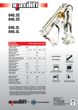
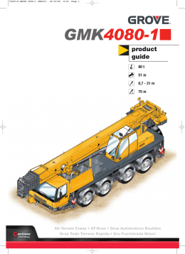
GMK2035E
product
guide
40 t
29 m
8,5 - 15 m
46 m
All-Terrain Crane • AT-Kran • Grue Automotrice Routière
Grúa Todo Terreno Rapida • Gru Fuoristrada Veloci
Contents • Inhalt • Contenu • Contenido • Contenuto
2
Specification
3
Technische Daten
Caractéristiques techniques
Características
4
5
6
Caratteristiche
7
Data • Daten • Caractéristiques • Datos • Dati
8
Dimensions • Abmessungen • Enncombrement • Dimensiones • Dimensioni
9
Load charts • Traglasten • Capacités de levage • Capacidades • Capacità
Notes • Hinweise • Notes • Notas • Note
Working Range • Arbeitsbereiche • Diagramme de levage • Gama de trabajo • Area di lavaro
Telescopic Boom • Teleskopausleger • Flèche principale • Pluma telescópica • Braccio telescopico
Swingaway • Klappspitze • Extension treillis • Plumín • Falcone
10
11
12
15
Notes • Hinweise • Notes • Notas • Note
Symbols • Symbolerklärung • Glossaire des symboles • Glosario de simbolos • Glossario dei simboli
19
GMK2035E
Manitowoc Crane CARE is the Manitowoc Crane Group’s unparalleled product support organisation. Manitowoc Crane CARE combines all aspects of parts, service, technical documentation,
technical support and training into one organisation. The program includes all of the Manitowoc Crane Group’s brands, which include, Potain, Grove, Manitowoc and National Crane.
For the care of your crane and the prosperity of your business, Manitowoc Crane CARE is your single source for customer support. Wherever, whenever, whatever – we’re there.
Manitowoc Crane CARE vereint alle Serviceleistungen der Manitowoc Crane Group im Produktsupport vor und nach dem Verkauf: Ersatzteile, Service, technische Dokumentation, technischer
Support und Schulung, alles unter einem Dach. Dieser Service erstreckt sich auf alle Marken der Manitowoc Crane Group: Potain, Grove, Manitowoc und National Crane.
Damit Ihr Kran leistungsfähig bleibt und Ihr Erfolg gesichert ist, bietet Ihnen Manitowoc Crane CARE einen umfassenden Support aus einer Hand. Zu jeder Zeit, an jedem Ort, für jeden Fall –
wir sind für Sie da.
Organisation hors pair dédiée au support technique des produits de Manitowoc Crane Group, Manitowoc Crane CARE réunit au sein d’une même entité tous les aspects du service : pièces de
rechange, service après-vente, publication technique, assistance technique et formation. Ce programme s’adresse à toutes les marques de Manitowoc Crane Group : Potain, Grove, Manitowoc et
National Crane.
Pour assurer l’entretien de vos grues et la prospérité de votre entreprise, Manitowoc Crane CARE constitue votre unique interlocuteur du service à la clientèle. Où que vous soyez, quel que soit
votre besoin, vous pouvez toujours compter sur nous !
Manitowoc Crane CARE, es la organización post-venta y soporte técnico de Manitowoc Crane Group. Manitowoc Crane CARE combina todos los aspectos de piezas de repuesto, servicio,
documentación técnica, apoyo técnico y formación en un único lugar. El programa también incluye todas las ramas Manitowoc Crane Group que engloba Potain, Grove, Manitowoc y National
Crane.
Para el cuidado de su grúa y la prosperidad de su negocio, Manitowoc Crane CARE, es la forma más sencilla de ayudarle. Donde sea y cuando sea, nosotros estamos allí.
Manitowoc Crane CARE è l’ineguagliabile organizzazione di supporto di Manitowoc Crane Group. Manitowoc Crane CARE gestisce tutte le attività legate a pezzi di ricambio, documentazione
tecnica, assistenza tecnica e formazione riunite in un unico punto di riferimento. Questo servizio è attivo per tutti i marchi di Manitowoc Crane Group e precisamente Potain, Grove, Manitowoc e
National Crane.
Per l’assistenza delle Vostre gru e per la redditività dei Vostri affari, Manitowoc Crane CARE è l’insostituibile Vostra risorsa in questo settore. In ogni posto, tutte le volte, per qualsiasi necessità –
noi ci siamo
Specification
Boom
8,9 m to 29,0 m four section full power boom.
Maximum tip height 32,0 m.
Boom elevation
1 cylinder with safety valve, boom angle from -3° to +82°.
Load moment and independent anti-two
block system
Load moment and independent anti-two block system with audio-visual
warning and control lever lock-out. These systems provide electronic
display of boom angle, length, radius, tip height, relative load moment,
maximum permissible load, load indication and warning of impending twoblock condition with lock-out hoist function.
Cab
Aluminium, full vision, safety glass, adjustable operator's seat with
suspension, engine-independent heater. Armrest-integrated crane controls.
Ergonomically arranged instrumentation and crane operating controls.
Drive/steer controls.
Slewing
Axial piston fixed displacement motor, planetary gear, service brake and
holding brake.
Counterweight
Fixed 3 tonnes.
Engine
See carrier.
Hydraulic system
2 separate pump circuits operating in an open circuit with 1 axial piston
variable displacement pump (load sensing) and 1 geared constant delivery
pump for slewing. Thermostatically controlled oil cooler. Tank capacity: 490 l.
Control system
Stepless control of all crane movements using control levers with
automatic reset to zero. ECOS
Hoist
Rope drum with special grooving and integrated planetary gear with
multiple disk brake and axial piston motor. Drum rotation indicator.
* Optional equipment
Bi-fold swingaway, 8,5/15 m (Manual offset 0°, 20°, 40°).
Bi-fold swingaway, 8,5/15 m (Hydraulically offset 0° - 40°).
Cab tiltable (approx. 20°).
Additional 3 tonnes counterweight including rigging cylinders (total
counterweight 6 tonnes). Hydraulic removal system (from crane cab).
Carrier
Chassis
Special 2-axle chassis, all-welded torsion-resistant box type construction
in high strength steel.
Outriggers
3
4 hydraulically telescoping beams with vertical cylinders and outrigger
pads. Independent horizontal and vertical movement control on each side
of carrier and from the crane operator’s cab. Electronic level indicator with
automatic levelling system.
Engine
Mercedes-Benz OM906LA, diesel, 6-cylinder, water cooled, turbocharged
and intercooled, 205 kW (279 PS) at 2300 rpm (80/1269 EWG - fan loose),
max. torque: 1100 Nm at 1300 rpm. Fuel tank capacity: 300 l.
Engine emission: EUROMOT / EPA / CARB (non-road).
Transmission
ZF-AS TRONIC automatic, 12 forward and 2 reverse speeds.
Single speed transfer case with inter-axle differential lock.
Drive/Steer
4 x 4 x 4.
Axle lines
2 axle lines. Axle lines 1 and 2 steered and driven.
Suspension
Hydropneumatic suspension and hydraulic lockout. Longitudinal and
transverse level control with automatic on-highway levelling system. Range
+110 mm/-110 mm.
Tyres
4 tyres, 14.00 R25.
Steering
Dual circuit, Servocom power steering with emergency steering pump.
Separate steering of the 2nd axle line for all-wheel steering and crabbing.
Brakes
Service brake: pneumatic dual circuit, acting on all wheels, air dryer.
Anti-lock braking system (ABS). Permanent brake: exhaust brake and
constant throttle brake. Parking brake: pneumatically operated
spring-loaded brake, acting on all wheels.
Cab
Aluminium, 2-man-design, safety glass, driver seat with hydraulic
suspension, engine-dependent hot water heater. Complete instrumentation
and driving controls. 60° tilt forward for engine access.
Electrical system
Three-phase alternator 28 V/80 A, 2 batteries 12 V/170 Ah. Lighting system
and signals 24 V.
*Optional equipment
Electric driveline retarder.
4 tyres 16.00 R25 (vehicle width 2,75 m).
Engine-independent hot water heater, with engine pre-heater.
*Further optional equipment upon request
GMK2035E
Superstructure
Technische Daten
Kranoberwagen
Teleskopausleger
4
Von 8,9 m bis 29,0 m ausfahrbarer, vierteiliger, vollteleskopierbarer
Ausleger. Maximale Rollenhöhe 32,0 m.
Wippwerk
1 Zylinder mit Sicherheits-Rückschlagventil.
Auslegerverstellwinkel -3° bis +82°.
Elektronisches Lastmomentbegrenzer und
unabhängiges Hubendschalter System
Elektronischer Lastmomentbegrenzer mit hör- und sichtbarer Vorwarnung
sowie automatischer Abschaltung, Digitalanzeige für tatsächliche und
zulässige Belastung, Ausladung und diverse Zustände. Unabhängiges
Hubendschalter System mit Abschaltfunktion.
Kranfahrerkabine
Vollsicht-Aluminium-Kabine, Sicherheitsglas, verstellbarer Fahrersitz mit
Dämpfung. In Armlehnen integrierte Kransteuereinrichtung. Ergonomisch
angeordnete Steuer- und Kontrolleinrichtungen. Motorunabhängige
Heizung. Fahr - und Lenkeinrichtung.
Drehwerk
Axialkolben-Konstantmotor, Planetengetriebe, Betriebs- und Haltebremse.
Gegengewicht
Kranunterwagen
Rahmen
2-Achs-Spezialfahrzeug, geschweißte, torsionssteife Kastenkonstruktion
aus hochfestem Feinkornstahl.
Abstützung
4 hydraulisch teleskopierbare Schiebeträger mit Abstützzylindern und
Abstützplatten, beidseitig vom Unterwagen und aus der Kranfahrerkabine
einzeln horizontal und vertikal steuerbar. Elektronische Niveauanzeige mit
automatischer Nivellierung.
Motor
Mercedes-Benz OM906LA, 6 Zylinder Diesel, Wasserumlaufkühlung
mit Abgasturbolader und Ladeluftkühler, 205 kW (279 PS) bei
2300 min-1 (80/1269/EWG Ventilator lose), max. Drehmoment 1100 Nm bei
1300 min-1. Kraftstoffbehälter: 300 l.
Motoremission: EUROMOT / EPA / CARB (non-road).
Getriebe
ZF-AS TRONIC Getriebeautomat, 12 Gänge vorwärts und 2 Gänge
rückwärts. Verteilergetriebe 1 stufig mit Längsdifferentialsperre.
Antrieb/Lenkung
4 x 4 x 4.
Achslinien
2 Achslinien. Achslinie 1 und 2 gelenkt und angetrieben.
3 t.
Motor
siehe Kranunterwagen
Hydrauliksystem
2 separate Pumpenkreisläufe im offenen Kreislaufe mit 1 AxialkolbenVerstellpumpe (Load-Sensing) und 1 Zahnrad-Konstantpumpe für das
Drehwerk. Thermostatisch gesteuerter Ölkühler.
Tankvolumen: 490 l Hydrauliköl.
Steuerung
Stufenlose Regelung aller Kranbewegungen über Steuerhebel mit
automatischer Nullstellung. ECOS
Hubwerk
Seiltrommel mit Spezialrillung und innenliegendem Planetengetriebe mit
Lamellenbremse und Axialkolbenmotor. Hubwerksdrehmelder.
* Zusatzausrüstung
Doppelklappspitze 8,5/15 m (0°, 20° 40° manual adwinkelbar).
Doppelklappspitze 8,5/15 m (hydraulisch einstellbar 0° - 40°).
Kranfahrerkabine, ca. 20º Kippbar.
Zusatzgewicht 3 t incl. Gegengewichtshubwerk.
(Gesamtgegengewicht 6 t), hydraulisches Rüstsystem (aus der
Kranfahrerkabine bedienbar).
Federung
Hydropneumatische Federung und hydraulische Blockierung.
Neigungsverstellung in alle Richtungen und automatische
Straßenfahrtniveaueinstellung. Federweg +110mm/-110mm.
Bereifung
4 Reifen, Größe 14.00 R25.
Lenkung
Zweikreis-Servocom Lenkung mit Notlenkpumpe. Separate Lenkung der 2.
Achslinie für Allradlenkung und Krabbengang.
Bremsen
Betriebsbremse: pneumatische Zweikreisbremse, auf alle Räder wirkend,
Lufttrockner. Automatischer Blockier-Verhinderer (ABV). Dauerbremse:
Motorklappenbremse mit Konstantdrossel. Feststellbremse:
druckluftbetätigte Federspeicherbremse auf 1. und 2. Achslinie wirkend.
Fahrerhaus
Aluminium, 2-Mann-Fahrerhaus, Sicherheitsglas, hydraulisch gedämpfter
Fahrersitz, motorabhängige Warmwasserheizung. Kontroll- und
Bedienungseinrichtung für Fahrbetrieb. 60° nach vorn kippbar für
Motorwartung.
Elektrische Anlage
GMK2035E
Drehstromlichtmaschine 28 V/80 A, 2 Batterien 12 V/170 Ah, Beleuchtung
und Signaleinrichtung 24 V.
* Zusatzausrüstung
Elektrische Wirbelstrombremse.
4 Reifen, Größe 16.00 R25 (Fahrzeugbreite 2,75 m).
Motorunabhängige Warmwasser-Standheizung mit Motorvorwärmung.
*Weitere Zusatausrüstungen auf Anfrage
Caractéristiques techniques
Flèche
Flèche quatre éléments, de 8,9 m à 29,0 m, à télescopage entièrement
hydraulique. Hauteur maximum de tête de flèche 32,0 m.
Relevage
1 vérin avec soupape de sécurité, angle de relevage de -3° à +82°.
Contrôleur d’état de charge et dispositif de
fin de course haute crochet indépendant
Equipements électronique de contrôle de charge et de fin de course haute
crochet indépendants avec dispositifs de signalisation sonore et visuelle et
de coupure des mouvements. Affichage digital d’angle et de longueur de
flèche, de portée, de hauteur de tête de flèche, de moment relatif, de
charge maximum autorisée, d’état de charge et d’approche de fin de
course haute crochet avec coupure du mouvement de montée de treuil.
Cabine
Cabine Aluminium, panoramique, verre de sécurité, siège réglable à
suspension, chauffage autonome. Manipulateurs de commandes de grue
intégrés aux accoudoirs. Disposition ergonomique de l’instrumentation et
des commandes. Commandes de translation et direction.
Orientation
Dispositif d’orientation par moteur hydraulique à pistons axiaux, réducteur
à planétaires, frein de service et frein d’immobilisation.
Contrepoids
Contrepoids fixe de 3 tonnes.
Moteur
Voir porteur.
Système hydraulique
2 circuits de pompe séparés dans circuit ouvert avec 1 pompe à pistons
axiaux (Load Sensing), et 1 pompe à engrenages à cylindrée constante
pour l'orientation. Refroidisseur d'huile à commande thermostatique.
Volume du réservoir: environ 490 l.
Commande
Réglage en continu de tous les mouvements de la grue par manipulateurs
de commande avec remise à zéro automatique. ECOS
Treuil de levage
Tambour rainuré, réducteur à planétaires, freins multidisques et moteur à
pistons axiaux. Indicateur de rotation.
* Equipements optionnels
Extension treillis repliable double 8,5 / 15 m (inclinable à 0°, 20°, 40°).
Extension treillis repliable double 8,5 / 15 m (déport hydraulique 0° - 40°).
Cabine de grutier, inclinable (angle d’inclinaison environ 20º).
Contrepoids supplémentaire de 3 t. (Contrepoids total 6 t), dispositif de
dépose hydraulique (commandé depuis la cabine de superstructure).
Porteur
Châssis
Porteur spécial, 2 lignes d'essieu, construction soudée type caisson,
résistant à la torsion, en acier de haute résistance.
Calage
5
4 poutres à télescopage hydraulique, avec vérins et patins d’appui.
Commande indépendante des mouvements verticaux et horizontaux sur
les deux côtés du porteur et dans la cabine de conduite. Indicateur de
niveau électronique avec système de mise à niveau automatique.
Moteur
Mercedes-Benz OM906LA, diesel, 6 cylindres turbo, refroidissement par
circulation d'eau et refroidisseur d'air de suralimentation, 205 KW
(279 PS) à 2300 min-1 (80/1269 EWG - ventilateur libre). Couple maxi 1100
Nm à 1300 min-1. Capacité du réservoir : env. 300 l.
Les émissions gaz et fumées EUROMOT / EPA / CARB (tout terrain).
Boîte de vitesses
Boîte de vitesses automatique ZF-AS TRONIC, 12 rapports de marche
avant et 2 rapports de marche arrière. Boîte de transfert avec verrouillage
longitudinal du différentiel. Blocages de différentiels : longitudinal dans la
boîte de transfert et transversaux.
Direction/Transmission
4 x 4 x 4.
Lignes d'essieu
2 lignes d'essieu. Lignes d'essieu 1 et 2 sont directrices et motrices.
Suspension
Suspension hydropneumatique et de verrouillages hydrauliques.
Commandes de mise à niveau longitudinal et transversal et dispositif de
mise à niveau automatique en position route.
Débattement: +110 mm/-110 mm.
Pneumatiques
4 pneus, 14.00 R25.
Direction
Direction assistée à deux circuits avec pompe de secours. Direction
séparée pour le 2éme essieu pour direction toutes roues directrices et
déplacement latéral (marche en crabe).
Freins
Frein de service: frein pneumatique agissant sur toutes les roues, à 2
circuits, dessiccateur. Dispositif anti-blocage (ABS). Frein ralentisseur: par
clapet sur échappement et frein sur distribution. Frein de stationnement: à
ressort à commande pneumatique agissant sur les lignes d'essieu 1 et 2.
Cabine
Aluminium, 2 places, verre trempé, siège du conducteur à suspension
hydraulique, chauffage à eau chaude dépendant du moteur.
Equipement de contrôle et de conduite. Inclinaison de 60° vers l'avant pour
accés moteur.
Installation électrique
Génératrice triphasée 28 V/80 A, 2 batteries 12 V/170 Ah, équipement
d'éclairage et de signalisation routière 24 V.
* Equipements optionnels
Frein à courants de Foucault.
4 pneus 16.00 R25 (largeur du véhicule 2,75 m)
Chauffage auxiliaire â eau chaude, indépendant du moteur, avec
préchauffage du moteur.
*Autres équipements optionnels sur demande
GMK2035E
Superstructure
Características
Superestructura
Pluma
6
De 8,9 m a 29,0 m cuatro tramos de telescopaje totalmente hidráulico.
Altura máxima en punta 32,0 m.
Elevación de pluma
Un cilindro con válvula de seguridad. Angulo de pluma desde -3°
hasta +82°.
Sistema Indicador del Momento de Carga y
de Final de Carrera del Gancho
Sistema Indicador del Momento de Carga y de Final de Carrera del
Gancho, con alarma audio-visual y bloqueo automático de las palancas.
Este sistema incluye pantalla digital con indicación de ángulo de pluma,
longitud, radio, altura de cabeza de pluma, momento de carga relativo,
carga máxima permisible, carga real y alarma de fin de carrera del
gancho con bloqueo del movimiento de elevación.
Cabina
De Aluminio, amplia visibilidad, cristales de seguridad, asiento del
operador ajustable y con suspensión. Calefacción independiente del
motor. Controles de la grúa integrados en el apoya-brazos. Controles de
operación de la grúa e instrumentación ergonómicamente situados.
Controles de traslación/dirección.
Giro
Con motor de pistón axial, engranaje planetario, freno de servicio y freno
de retención.
Contrapeso
Fijo de 3 Tm.
Motor
Ver chasis.
Sistema hidráulico
Dos circuitos separados, funcionando un circuito abierto con una
bomba de pistón axial de desplazamiento variable (con sensor de
demanda de carga) y una bomba de engranaje constante para el giro.
Radiador de aceite con control por termostato. Capacidad del depósito:
490 litros.
Sistema de control
Controles contínuos de todos los movimientos de la grúa, usando
palancas de control con retorno automático a cero. ECOS
Cabrestante
Tambor de cable con acanalado especial y engranaje planetario integral
con motor de pistón axial y freno de disco múltiple. Indicador de
rotación del cabrestante.
GMK2035E
* Equipos opcionales
Plumín articulado en 2 secciones, 8,5 / 15m (Angulable 0°, 20° 40°).
Plumín articulado en 2 secciones, 8,5 / 15m (Angulable hidráulicamente
0° - 40°).
Cabina de la grúa, basculable (approx. 20º).
Contrapeso adicional de 3 Tm. incluyendo cilindro de colocación
(Contrapeso total 6 Tm.). Sistema hidráulico para desmontaje (desde la
cabina de la grua).
Chasis
Bastidor
Chasis especial de dos ejes de construcción soldada tipo cajón,
resistente a la torsión, en acero de alta resistencia.
Estabilizadores
Cuatro vigas telescópicas hidráulicas con cilindros verticales y placas de
apoyo. Controles independientes para los movimientos horizontales y
verticales, con controles en ambos lados del chasis y en la cabina de la
grúa. Indicador electrónico de nivel con sistema de nivelación automática.
Motor
Diesel Mercedes-Benz OM906LA, 6 cilindros, refrigerado por agua,
turbo-alimentado y post-refrigerado, 205 Kw (279 PS) a 2.300 r.p.m.
(80/1269 EWG - ventilador desconectado), par máximo: 1100 Nm, a
1.300 r.p.m. Capacidad del Depósito de Combustible: 300 litros.
Emisión de gases: Según normas EUROMOT / EPA / CARB (fuera de
carretera).
Transmisión
Transmisión automática ZF-AS TRONIC, 12 velocidades adelante y 2 atrás.
Caja de transferencia de una velocidad con bloqueo de diferencial entre
ejes.
Tracción/Dirección
4 x 4 x 4.
Ejes
2 ejes en línea. Ambos motrices y directrices.
Suspensión
Suspensión hidroneumática y bloqueo hidráulico. Control de nivel
longitudinal y transversal con sistema de nivelación automática en
carretera. Desplazamiento +110 mm./ -110 mm.
Neumáticos
4 neumáticos, 14.00 R25.
Dirección
Dirección servo-asistida con doble circuito y bomba de dirección de
emergencia. Dirección independiente del segundo eje para dirección a
todas las ruedas y dirección tipo cangrejo.
Frenos
Frenos de servicio: Neumático con doble circuito, actuando sobre todas
las ruedas, secador de aire. Sistema antibloqueo de frenos (ABS). Freno
contínuo: Freno sobre el escape, con estrangulamiento contínuo. Freno
de Aparcamiento: Operado neumáticamente y aplicado por muelle
sobre todas las ruedas.
Cabina
De Aluminio, para dos personas, cristales de seguridad, asientos del
conductor con suspensión hidráulica, calefacción por agua caliente del
motor. Controles e instrumentación para conducción del vehículo.
Inclinable 60° hacia adelante para acceso al motor.
Sistema eléctrico
Trifásico, alternador de 28 V/80 A, 2 baterías 12 V/170 Ah. Sistema de
alumbrado y señalización a 24 V.
* Equipos opcionales
Retardador eléctrico.
4 neumáticos 16.00 R25 (Anchura del vehículo: 2,75 m.)
Calefacción independiente del motor por agua caliente, con
precalentamiento del motor.
* Siguientes equipos bajo demanda
Caratteristiche
Braccio
A 4 sezioni da 8,9 a 29 m con sfilamento completamente idraulico.
Altezza massima: 32 m.
Elevazione Braccio
Un cilindro idraulico con valvola di blocco, angolo braccio da -3° a +82°.
Limitatore di carico con blocco dei
movimenti
Limitatore di carico e blocco dei movimenti con allarme visivo e sonoro
e controllo dell’esclusione delle leve. Questo sistema è provvisto di
display elettronico riportante l’angolo del braccio, la lunghezza, il raggio
di lavoro, altezza di lavoro, il momento, il peso ammissibile,
il peso attuale e allarme di blocco movimenti e funzioni argano.
Cabina
Costruita in alluminio, grande visibilità, cristalli di sicurezza, sedile
regolabile con sospensione. Riscaldamento ad acqua indipendente dal
motore. Comandi della gru integrati nei braccioli, strumentazione di
controllo e servizio. Comandi sterzo e guida.
Rotazione
Motore a pistoni assiali a portata fissa,riduttore planetario, freno di servizio
e freno d'arresto.
Contrappeso
Da 3 ton, fisso.
Motore
Vedi carro
Impianto idraulico
2 circuiti separati operanti a circuito aperto, con una pompa a pistoni
assiali a portata variabile (load sensing) e una pompa a ingranaggi per la
rotazione. Scambiatore di calore controllato termostaticamente.
Capacità del serbatoio: 490 litri.
Comandi
Tutti i movimenti della gru sono variabili progressivamente a mezzo di
servocomando idraulico a regolazione elettrica e leve di comando con
richiamo automatico al punto zero. ECOS
Argano
Motore a pistoni assiali con riduttore a planetari e freno automatico.
Indicatore di rotazione argano.
* Accessori opzionali
Falcone ripiegabile da 8,5/15m inclinabile a 0°, 20°, 40°.
Falcone ripiegabile da 8,5/15m (inclinazione idraulica 0° - 40°).
Cabina operatore ribaltable (circa 20º).
Supplementare da 3 ton incluso sistema di rimozione comandato
direttamente dalla cabina (Contrappeso totale 6 ton)
Carro
Telaio
Carro speciale, 2 assi, costruzione in acciaio scatolato ad alta
resistenza, resistente alla torsione.
Stabilizzatori
7
4 travi orizzontali con cilindri verticali e piatti d'appoggio, comandi
indipendenti dei movimenti orizzontali e verticali sui due lati del carro e
dalla cabina della torretta. Indicatori elettronici di livello con sistema di
messa in bolla automatico.
Motore
Mercedes Benz OM906LA diesel, 6 cilindri, turbo intercooled 205 kW
(279 PS) a 2300 giri/min (80/1269 EWG - senza ventole). Coppia max
1100 Nm a 1300 giri/min. Capacità del serbatoio: 300 litri. Emissioni
gassose allo scarico: EUROMOT / EPA / CARB (notori non stradali).
Trasmissione
ZF-AS TRONIC automatico 12 velocità avanti più 2 retromarcia. Ripartitore
a una velocità.
Assi
2 assi: (4 x 4 x 4). Tutti sterzanti e traenti.
Sospensioni
Sospensioni idro-pnueumatiche e bloccabili. Sistema di controllo del
livello longitudinale e trasversale, con livellamento automatico per la
circolazione su strada. Corsa +110 mm / - 110 mm.
Pneumatici
4 pneumatici montati in singolo 14.00 R 25.
Sterzo
Doppio circuito. Servoassistito con pompa d'emergenza.
Con comando separato per lo sterzo posteriore, è possibile eseguire la
sterzaFtura combinata e a granchio.
Freni
Di servizio: pneumatico a doppio circuito, agente su tutte le ruote,
essiccatore aria. Sistema antibloccaggio (ABS). Freno di stazionamento:
scarico frenato e controllo costante valvola.
Freno di parcheggio: con molle precaricate a comando pneumatico
agente sugli assi.
Cabina
In alluminio, 2 posti, cristalli di sicurezza, sedile del guidatore e del
passeggero con sospensione idraulica, riscaldamento ad acqua calda
dipendente dal motore. Completa strumentazione di controllo e guida.
Cabina ribaltabile di 60° per facilitare l’accesso al motore.
Impianto elettrico
Alternatore trifase 28V/55A, 2 batterie da 12V/170Ah. Impianto
d'illuminazione e segnalazione stradale 24V.
* Equipaggiamenti opzionali
Retarder elettrico su trasmissione.
Ruote da 16.00 R 25 (Larghezza macchina 2,75m)
Riscaldamento ad acqua calda indipendente dal motore.
* Altri a richiesta.
GMK2035E
Torretta
Data • Daten • Caractéristiques • Datos • Dati
8
Axle
Achse
Essieu
Eje
Asse
t
1
2
Total weight
Gesamtgewicht
Poids total
Peso total
Peso totale
12
12
24*
* incl. 3,0 t counterweight and bi-fold swingaway, incl. 3,0 t Gegengewicht und Doppelklappspitze, incl. 3,0 t contrepoids et extension treillis double,
incl. contrapeso de 3 Tm y plumín articulado, con a bordo 3,0t di zavorra, falcone ripiegabile
Lifting Capacity
Traglast
Force de levage
Capacidad de elevación
Capacità di sollevamento
Sheaves
Rollen
Poulies
Poleas
Carrucole
32 t
20 t
9t
5t
5
3
1
H/B
Weight
Gewicht
Poids
Peso
Peso
Parts of line
Stränge
Brins
Ramales de cable
Numero di funi
400 kg
250 kg
120 kg
100 kg
2 - 10
2-7
1-3
1
Possible load with the crane *
Mögliche Traglast am Kran *
Capacité possible sur la grue *
Carga posible con la grue *
Portata ammissibile con la gru *
32 t
20 t
9t
3,3 t
* varies depending on national regulations, variiert je nach Ländvorschrift, fonction des réglementations nationales,
variaciones dependio de las regulaciones nacionales, varia in funzione delle normative nazionali.
+
km/h
1
2
3
4
5
6
7
8
9
10
11
12
R1
R2
6,6
8,2
10,6
13,0
16,4
20,2
27,8
34,3
44,2
54,4
68,6
84,0
6,5
8,0
60%
14.00 R25
+
GMK2035E
Infinitely variable
stufenlos
progressivement variable
Infinitamente variable
Infinitamente variabile
0 – 130 m/min
single line
für einfachen Strang
brin simple
ramal simple
tiro a fune singola
-1
0 – 2,7 min
– 3˚ to + 82˚
approx. 29 s
ca. 29 s
env. 29 s
aproximadamente 29 s
circa 29 s
8,9 m to 29,0 m
approx. 66 s
ca. 66 s
env. 66 s
aproximadamente 66 s
circa 66 s
Rope
Seil
Câble
Cable
Fune
Max. permissible line pull
Maximal zulässige Seilzugkraft
Effort maximum autorisé sur brin simple
Potencia máxima admisible por ramal
Tiro massimo ammissibile della fune
13 mm/135 m
33 kN
Dimensions • Abmessungen • Encombrement • Dimensiones • Dimensioni
10215
3100
8910
17°
3423
3583
9
21°
2675
1442
1200
1100
3775
1350
376
8143
8377
104
2343
230
R 4 900
1
Ra
Radius all
steered
Rawheels
= Radius
all wheel steered
Radius allradgelenkt
Radius allradgelenkt
Rayon toutes les roues directrices
Radio de giro con todas las ruedas giradas
Raggio di curva con tutte le ruote sterzate
3768
2557
6325
GMK2035E
2550
90
92 840
6
Ra
Ra =
6200
R
90 0
99 64
7
Ra
R 31
00
R
R 6970
Ra 5820
3982
4400
1799
Load Charts • Traglasten • Capacités de levage • Capacidades • Capacità
Notes • Hinweise • Notes • Notas • Note
The lifting capacities correspond to EN 13000:2004.
10
The lifting capacities likewise fulfil the requirements of ISO 4305 and DIN 15019, Part 2, with regard to stability, and DIN 15018, Part 3, and FEM 5004 with regard to strength.
The lifting capacities are given in tonnes.
Lifting capacity = Payload + weight of hook block and suspending device
The lifting capacities for the main boom only apply with the jib dismantled.
Lifting capacities > 32 t require additional equipment
Lifting capacities > 38 t require special equipment
The right is reserved to modify the load-carrying capacities.
Note: The details in this brochure serve only as general information.
The determinant values for the operation of the crane are the lifting capacity tables belonging to it and the operating instructions.
Die Tragfähigkeiten entsprechen EN 13000:2004.
Die Tragfähigkeitswerte erfüllen ebenfalls die Anforderungen von ISO 4305 und DIN 15019 Teil 2 bezüglich Standsicherheit sowie von DIN 15018 Teil 3 und FEM 5004 bezüglich
Festigkeit.
Die Tragfähigkeitswerte sind in Tonnen angegeben.
Tragfähigkeit = Nutzlast + Gewicht der Hakenflasche und Anschlagmittel
Die Tragfähigkeitswerte für den Hauptausleger gelten nur bei demontierten Spitzenauslegern.
Die Tragfähigkeitswerte > 32 t erfordern eine Zusatzausrüstung.
Die Tragfähigkeitswerte > 38 t erfordern eine Sonderausrüstung.
Änderung der Tragfähigkeiten vorbehalten
Anmerkung: Die Daten dieser Broschüre dienen nur zur allgemeinen Information.
Maßgebend für den Betrieb des Kranes sind die zugehörigen Tragfähigkeitstabellen und die Bedienungsanleitung.
Les capacités de levage sont conformes à la norme EN 13000:2004.
Les capacités de levage respectent également les exigences des normes ISO 4305 et DIN 15019, paragraphe 2, relatives à la stabilité, ainsi que celles des normes DIN 15018
paragraphe 3 et FEM 5004 relatives à la résistance.
Les capacités de levage sont exprimées en tonnes.
capacité = charge utile + poids du crochet et du dispositif d'élingage
Les capacités de levage de la flèche principale ne sont valables que lorsque la fléchette est démontée.
Des capacités de levage supérieures à 32 tonnes exigent l'utilisation d'un dispositif supplémentaire.
Des capacités de levage supérieures à 38 tonnes exigent l'utilisation d'un dispositif spécial.
Le constructeur se réserve le droit d'apporter des modifications à ces capacités de levage.
Remarque : Les données de cette brochure ne sont fournies qu'à titre d'information générale.
La manipulation de la gru nécessite l'étude des tableaux de capacité et la lecture des guides d'utilisation correspondants.
Las capacidades de carga corresponden a EN 13000:2004.
Asimismo los valores de carga cumplen las disposiciones de las normas ISO 4305 y DIN 15019, 2.ª parte, respecto a la estabilidad, y DIN 15018, 3.ª parte, y FEM 5004
respecto a la fuerza.
Los valores de carga se dan en toneladas.
Capacidad de carga = Carga + peso de la garrucha del gancho y del mecanismo de elevación
Los valores de carga para la pluma principal sólo son válidos cuando no hay plumines instalados.
Valores de carga > 32 t requieren un mecanismo de elevación suplementario
Valores de carga > 38 t requieren una unidad especial
Se reserva el derecho a modificar las capacidades de carga.
Nota: Los detalles contenidos en este folleto sirven sólo como información general.
Los valores determinantes para el funcionamiento de la grúa son los cuadros de cargas correspondientes, así como las instrucciones de funcionamiento.
GMK2035E
Le tabelle di portata sono conformi alle norme EN 13000:2004.
I valori delle tabelle di portata sono conformi anche ai requisiti delle norme ISO 4305 e DIN 15019, Parte 2, per quanto riguarda la stabilità, ed alle norme DIN 15018, Parte 3,
e FEM 5004 per quanto riguarda il calcolo di resistenza della struttura .
I valori di portata sono indicati in tonnellate.
Capacità di portata = carico utile + peso del gancio e accessori di sollevamento
I valori delle tabelle di portata per il braccio principale si applicano solo con le punte bracci smontate.
Valori di portata > 32 t richiedono un’attrezzatura supplementare
Valori di portata > 38 t richiedono un’unità speciale
Si riserva il diritto di modificare i valori di portata .
Nota: i dettagli forniti nel presente opuscolo servono solo come informazioni di carattere generale.
I valori determinanti per il funzionamento della gru sono le tabelle di portata appartenenti alla gru stessa e le istruzioni di funzionamento
Load Charts • Traglasten • Capacités de levage • Capacidades • Capacità
Working range • Arbeitsbereiche • Diagramme de levage • Gama de trabajo • Area di lavoro
8,9 – 29,0 m
8,5/15,0 m
6,2 m
11
360˚
[m]
50
0°
+ 15,0
2,0
m
40°
2,0
2,0
40
+ 8,5
2,0
3,5
1,5
1,6
m
3,5
3,5
3,1
3,1
1,1
2,1
29,0 m
30
8,0
7,6
0,7
5,8
1,4
22,4 m
3,6
13,0
12,5
0,8
0,9
20
2,3
7,7
1,2
4,9
20,0
15,7
4,0
1,5
15,6 m
0,7
7,7
3,3
10
35,0*
5,4
20
16,6
10
0
R[m]
Hook block • Unterflasche • Crochet-moufle • Gancho • Ganci
(t)
H
(mm)
32E
2630
20E
2530
9E
2450
5 H/B
2050
THIS CHART IS ONLY A GUIDE AND SHOULD NOT BE USED TO OPERATE THE CRANE. The individual crane’s load chart, operating instructions and other instructional plates must be read and understood prior to operating the crane.
DIE DATEN IN DIESER TABELLE DIENEN NUR ZUR INFORMATION UND GELTEN NICHT FÜR DEN BETRIEB DES KRANS. Vor Inbetriebnahme des Krans sind dessen jeweilige Traglasttabelle, Betriebsanleitung und weitere Herstelleranleitungen durchzulesen und zu befolgen.
CETTE ILLUSTRATION EST FOURNIE A SIMPLE TITRE INDICATIF. NE L'UTILISEZ PAS POUR MANŒUVRER LA GRUE. La courbe de charge, les notices techniques et autres consignes d'utilisation doivent être lues et assimilées avant toute utilisation de cette grue.
ESTA TABLA ES MERAMENTE ORIENTATIVA Y NO DEBERÁ UTILIZARSE PARA TRABAJAR CON LA GRÚA. Antes de utilizar la grúa, han de leerse y entenderse la tabla de cargas individuales de la grúa, las instrucciones de funcionamiento y otras placas de instrucciones.
QUESTO GRAFICO SERVE SOLO DA GUIDA E NON DEVE ESSERE UTILIZZATO PER OPERARE CON LA GRU. Il grafico di carico, le istruzioni operative e altre targhe d’istruzione della gru individuale devono essere letti e compresi prima di azionare la gru.
GMK2035E
2,7
30
8,9 m
1,2
Load Charts • Traglasten • Capacités de levage • Capacidades • Capacità
Telescopic boom • Teleskopausleger • Flèche principale • Pluma telescópica • Braccio telescopico
12
8,9 – 29,0 m
6,2 m
360°
6t
EN 13000
m
2,5
3,0
4,0
5,0
6,0
7,0
8,0
9,0
10,0
11,0
12,0
13,0
14,0
15,0
16,0
18,0
20,0
22,0
24,0
26,0
8,9
40,0*
35,0*/31,0
26,0
20,5
16,6
12,3
15,6
19,0
22,4
25,0
23,5
20,0
16,4
14,2
11,7
9,6
8,0
20,0
20,0
17,8
15,7
13,2
11,3
9,2
7,7
6,5
6,0
5,4
15,0
15,0
15,0
14,3
12,7
10,7
9,0
8,1
7,2
6,3
5,5
4,9
4,4
3,9
13,0
13,0
13,0
12,5
11,5
10,4
8,9
7,7
6,6
5,7
5,3
4,9
4,5
4,0
3,3
2,7
25,7
10,5
10,5
10,5
9,9
9,2
8,5
7,6
6,7
5,8
5,1
4,4
3,9
3,5
2,7
2,4
2,0
29,0
8,0
8,0
7,8
7,6
7,4
7,1
6,6
5,8
5,2
4,6
4,0
3,6
2,9
2,3
1,9
1,5
1,2
* over rear, nach hinten, en arrière, por la parte trasera, sul posteriore.
8,9 – 29,0 m
6,2 m
360°
3t
EN 13000
GMK2035E
m
3,0
4,0
5,0
6,0
7,0
8,0
9,0
10,0
11,0
12,0
13,0
14,0
15,0
16,0
18,0
20,0
22,0
24,0
26,0
8,9
33,5*/3,1
24,5
19,1
15,3
12,3
15,6
19,0
22,4
25,0
23,5
18,9
15,0
12,0
9,4
7,7
6,4
20,0
20,0
17,6
14,1
11,3
9,1
7,6
6,6
5,6
4,9
4,2
15,0
15,0
15,0
13,0
10,4
9,4
8,1
6,8
5,8
5,0
4,4
3,8
3,4
3,0
13,0
13,0
13,0
12,5
10,1
8,4
7,3
6,7
5,9
5,1
4,5
3,9
3,5
3,1
2,5
2,0
25,7
10,5
10,5
10,5
9,8
8,2
7,0
6,0
5,2
4,5
4,0
3,7
3,2
2,9
2,3
1,8
1,4
29,0
8,0
8,0
7,8
7,6
6,9
5,9
5,2
4,5
4,0
3,5
3,1
2,7
2,1
1,6
1,2
0,9
0,7
* over rear, nach hinten, en arrière, por la parte trasera, sul posteriore.
THIS CHART IS ONLY A GUIDE AND SHOULD NOT BE USED TO OPERATE THE CRANE. The individual crane’s load chart, operating instructions and other instructional plates must be read and understood prior to operating the crane.
DIE DATEN IN DIESER TABELLE DIENEN NUR ZUR INFORMATION UND GELTEN NICHT FÜR DEN BETRIEB DES KRANS. Vor Inbetriebnahme des Krans sind dessen jeweilige Traglasttabelle, Betriebsanleitung und weitere Herstelleranleitungen durchzulesen und zu befolgen.
CETTE ILLUSTRATION EST FOURNIE A SIMPLE TITRE INDICATIF. NE L'UTILISEZ PAS POUR MANŒUVRER LA GRUE. La courbe de charge, les notices techniques et autres consignes d'utilisation doivent être lues et assimilées avant toute utilisation de cette grue.
ESTA TABLA ES MERAMENTE ORIENTATIVA Y NO DEBERÁ UTILIZARSE PARA TRABAJAR CON LA GRÚA. Antes de utilizar la grúa, han de leerse y entenderse la tabla de cargas individuales de la grúa, las instrucciones de funcionamiento y otras placas de instrucciones.
QUESTO GRAFICO SERVE SOLO DA GUIDA E NON DEVE ESSERE UTILIZZATO PER OPERARE CON LA GRU. Il grafico di carico, le istruzioni operative e altre targhe d’istruzione della gru individuale devono essere letti e compresi prima di azionare la gru.
Load Charts • Traglasten • Capacités de levage • Capacidades • Capacità
Telescopic boom • Teleskopausleger • Flèche principale • Pluma telescópica • Braccio telescopico
8,9 – 29,0 m
4,4 m
360°
13
6t
EN 13000
m
8,9
12,3
15,6
19,0
22,4
3,0
4,0
5,0
6,0
7,0
8,0
9,0
10,0
11,0
12,0
13,0
14,0
15,0
16,0
18,0
20,0
22,0
24,0
26,0
28,0
22,5
18,7
13,1
25,0
22,5
16,5
13,5
10,4
8,3
6,8
5,6
20,0
20,0
15,0
12,2
9,8
8,2
7,0
5,9
5,0
4,3
3,7
15,0
15,0
14,4
11,1
10,1
8,4
7,2
6,0
5,1
4,4
3,8
3,4
3,0
2,6
13,0
13,0
13,0
10,8
8,8
7,9
7,0
6,1
5,2
4,5
4,0
3,5
3,1
2,7
2,2
1,7
8,9 – 29,0 m
4,4 m
360°
25,7
10,5
10,5
10,5
8,6
7,1
6,1
5,2
4,7
4,3
3,7
3,2
2,8
2,5
1,9
1,5
1,2
29,0
8,0
8,0
7,8
7,0
6,0
5,1
4,5
3,9
3,4
3,0
2,7
2,3
1,8
1,3
1,0
0,7
3t
m
8,9
12,3
15,6
19,0
22,4
25,7
29,0
3,0
4,0
5,0
6,0
7,0
8,0
9,0
10,0
11,0
12,0
13,0
14,0
15,0
16,0
18,0
20,0
27,0
21,0
14,4
10,0
25,0
18,0
13,6
10,4
8,0
6,3
5,0
4,1
20,0
15,9
11,5
10,0
8,0
6,5
5,3
4,4
3,7
3,1
2,6
15,0
15,0
11,6
9,5
7,7
6,4
5,4
4,5
3,8
3,2
2,8
2,4
2,0
1,8
13,0
13,0
10,5
8,8
7,5
6,2
5,3
4,5
3,9
3,3
2,9
2,5
2,2
1,9
1,4
1,1
10,5
10,1
7,9
6,8
5,7
4,8
4,1
3,5
3,0
2,6
2,2
1,9
1,6
1,2
0,9
8,0
7,7
6,2
5,2
4,3
3,7
3,1
2,7
2,3
2,0
1,7
1,4
1,0
0,7
THIS CHART IS ONLY A GUIDE AND SHOULD NOT BE USED TO OPERATE THE CRANE. The individual crane’s load chart, operating instructions and other instructional plates must be read and understood prior to operating the crane.
DIE DATEN IN DIESER TABELLE DIENEN NUR ZUR INFORMATION UND GELTEN NICHT FÜR DEN BETRIEB DES KRANS. Vor Inbetriebnahme des Krans sind dessen jeweilige Traglasttabelle, Betriebsanleitung und weitere Herstelleranleitungen durchzulesen und zu befolgen.
CETTE ILLUSTRATION EST FOURNIE A SIMPLE TITRE INDICATIF. NE L'UTILISEZ PAS POUR MANŒUVRER LA GRUE. La courbe de charge, les notices techniques et autres consignes d'utilisation doivent être lues et assimilées avant toute utilisation de cette grue.
ESTA TABLA ES MERAMENTE ORIENTATIVA Y NO DEBERÁ UTILIZARSE PARA TRABAJAR CON LA GRÚA. Antes de utilizar la grúa, han de leerse y entenderse la tabla de cargas individuales de la grúa, las instrucciones de funcionamiento y otras placas de instrucciones.
QUESTO GRAFICO SERVE SOLO DA GUIDA E NON DEVE ESSERE UTILIZZATO PER OPERARE CON LA GRU. Il grafico di carico, le istruzioni operative e altre targhe d’istruzione della gru individuale devono essere letti e compresi prima di azionare la gru.
GMK2035E
EN 13000
Load Charts • Traglasten • Capacités de levage • Capacidades • Capacità
Telescopic boom • Teleskopausleger • Flèche principale • Pluma telescópica • Braccio telescopico
14
8,9 – 15,6 m
0°
6t
EN 13000
m
8,9
12,3
15,6
3,0
4,0
5,0
6,0
7,0
8,0
9,0
10,0
11,0
12,0
13,0
9,9
8,0
6,6
5,5
10,2
8,3
6,9
5,9
5,0
4,3
3,7
3,3
10,3
8,5
7,1
6,0
5,2
4,5
3,9
3,4
3,0
2,7
2,3
8,9 – 15,6 m
0°
3t
EN 13000
m
8,9
12,3
15,6
3,0
4,0
5,0
6,0
7,0
8,0
9,0
10,0
11,0
12,0
13,0
9,9
8,0
6,6
5,5
10,2
8,3
6,9
5,8
4,9
3,9
3,2
2,5
10,3
8,4
7,0
6,0
5,0
4,1
3,4
2,8
2,3
1,9
1,5
8,9 – 15,6 m
360°
3t
GMK2035E
EN 13000
m
8,9
12,3
15,6
3,0
4,0
5,0
6,0
7,0
8,0
9,0
10,0
6,5
4,6
3,4
2,5
6,9
5,0
3,8
2,9
2,2
1,5
1,0
7,1
5,2
4,0
3,1
2,4
1,8
1,3
0,9
THIS CHART IS ONLY A GUIDE AND SHOULD NOT BE USED TO OPERATE THE CRANE. The individual crane’s load chart, operating instructions and other instructional plates must be read and understood prior to operating the crane.
DIE DATEN IN DIESER TABELLE DIENEN NUR ZUR INFORMATION UND GELTEN NICHT FÜR DEN BETRIEB DES KRANS. Vor Inbetriebnahme des Krans sind dessen jeweilige Traglasttabelle, Betriebsanleitung und weitere Herstelleranleitungen durchzulesen und zu befolgen.
CETTE ILLUSTRATION EST FOURNIE A SIMPLE TITRE INDICATIF. NE L'UTILISEZ PAS POUR MANŒUVRER LA GRUE. La courbe de charge, les notices techniques et autres consignes d'utilisation doivent être lues et assimilées avant toute utilisation de cette grue.
ESTA TABLA ES MERAMENTE ORIENTATIVA Y NO DEBERÁ UTILIZARSE PARA TRABAJAR CON LA GRÚA. Antes de utilizar la grúa, han de leerse y entenderse la tabla de cargas individuales de la grúa, las instrucciones de funcionamiento y otras placas de instrucciones.
QUESTO GRAFICO SERVE SOLO DA GUIDA E NON DEVE ESSERE UTILIZZATO PER OPERARE CON LA GRU. Il grafico di carico, le istruzioni operative e altre targhe d’istruzione della gru individuale devono essere letti e compresi prima di azionare la gru.
Load Charts • Traglasten • Capacités de levage • Capacidades • Capacità
Swingaway • Klappspitze • Extension treillis • Plumin • Falcone
25,6 – 29,0 m
8,5 m
6,2 m
360°
15
6t
EN 13000
m
25,6
m
8,5
0°
5,0
6,0
7,0
8,0
9,0
10,0
11,0
12,0
13,0
14,0
15,0
16,0
18,0
20,0
22,0
24,0
26,0
28,0
30,0
32,0
4,4
4,4
4,4
4,4
4,4
4,4
4,4
4,4
4,4
4,4
4,3
3,8
3,1
2,5
2,0
1,7
1,4
1,1
0,9
20°
4,4
4,3
4,1
4,0
3,8
3,7
3,6
3,5
3,4
3,1
2,5
2,0
1,7
1,4
1,1
0,9
40°
29,0
8,5
*0°-20°
2,5
2,4
2,3
2,2
2,1
2,1
2,0
1,9
1,9
1,8
1,7
1,6
1,5
1,4
1,1
0,9
3,3
3,2
3,1
3,0
2,9
2,9
2,8
2,8
2,7
2,7
2,2
1,8
1,4
*20-40°
0°
20°
2,0
2,0
1,9
1,9
1,8
1,8
1,8
1,7
1,7
1,6
1,6
1,5
1,4
3,5
3,5
3,5
3,5
3,5
3,5
3,5
3,5
3,5
3,5
3,5
3,1
2,5
2,1
1,7
1,4
1,1
0,9
0,7
3,5
3,5
3,5
3,5
3,5
3,5
3,5
3,4
3,1
2,5
2,1
1,7
1,4
1,1
0,9
0,7
40°
*0°-20°
*20-40°
2,5
2,4
2,3
2,2
2,1
2,1
2,0
1,9
1,8
1,7
1,7
1,6
1,4
1,1
0,9
0,7
3,1
3,1
3,0
2,9
2,9
2,9
2,8
2,7
2,7
2,2
1,8
1,5
1,2
2,0
1,9
1,9
1,9
1,8
1,8
1,8
1,7
1,7
1,6
1,6
1,5
1,2
* Luffing under load, Inter Teillast wippbar, Inclinaison sous charge, Angulación con carga, Brandeggio sotte carico.
25,6 – 29,0 m
15,0 m
6,2 m
360°
6t
EN 13000
25,6
m
0°
7,0
8,0
9,0
10,0
11,0
12,0
13,0
14,0
15,0
16,0
18,0
20,0
22,0
24,0
26,0
28,0
30,0
32,0
34,0
29,0
15,0
2,5
2,5
2,5
2,5
2,5
2,5
2,5
2,5
2,5
2,5
2,3
2,1
2,0
1,8
1,6
1,3
1,1
0,9
0,7
20°
2,2
2,1
2,0
2,0
1,9
1,8
1,7
1,6
1,6
1,5
1,4
1,3
1,1
0,9
0,7
40°
1,6
1,5
1,5
1,4
1,4
1,3
1,3
1,3
1,2
1,0
0,8
15,0
*0°-20°
1,3
1,2
1,2
1,1
1,1
1,0
1,0
0,9
0,8
0,8
0,7
0,7
0,7
0,6
*20-40°
0°
20°
0,9
0,9
0,8
0,8
0,8
0,7
0,7
0,7
0,7
0,6
0,6
2,0
2,0
2,0
2,0
2,0
2,0
2,0
2,0
2,0
2,0
2,0
2,0
1,9
1,6
1,3
1,1
0,9
0,7
2,1
2,0
2,0
1,9
1,9
1,8
1,7
1,6
1,5
1,5
1,3
1,1
0,9
0,7
40°
*0°-20°
*20-40°
1,5
1,5
1,4
1,4
1,4
1,3
1,3
1,2
1,0
0,8
1,3
1,2
1,2
1,1
1,1
1,0
0,9
0,9
0,8
0,8
0,7
0,7
0,7
0,6
0,9
0,9
0,8
0,8
0,8
0,7
0,7
0,7
0,7
0,6
* Luffing under load, Inter Teillast wippbar, Inclinaison sous charge, Angulación con carga, Brandeggio sotte carico.
THIS CHART IS ONLY A GUIDE AND SHOULD NOT BE USED TO OPERATE THE CRANE. The individual crane’s load chart, operating instructions and other instructional plates must be read and understood prior to operating the crane.
DIE DATEN IN DIESER TABELLE DIENEN NUR ZUR INFORMATION UND GELTEN NICHT FÜR DEN BETRIEB DES KRANS. Vor Inbetriebnahme des Krans sind dessen jeweilige Traglasttabelle, Betriebsanleitung und weitere Herstelleranleitungen durchzulesen und zu befolgen.
CETTE ILLUSTRATION EST FOURNIE A SIMPLE TITRE INDICATIF. NE L'UTILISEZ PAS POUR MANŒUVRER LA GRUE. La courbe de charge, les notices techniques et autres consignes d'utilisation doivent être lues et assimilées avant toute utilisation de cette grue.
ESTA TABLA ES MERAMENTE ORIENTATIVA Y NO DEBERÁ UTILIZARSE PARA TRABAJAR CON LA GRÚA. Antes de utilizar la grúa, han de leerse y entenderse la tabla de cargas individuales de la grúa, las instrucciones de funcionamiento y otras placas de instrucciones.
QUESTO GRAFICO SERVE SOLO DA GUIDA E NON DEVE ESSERE UTILIZZATO PER OPERARE CON LA GRU. Il grafico di carico, le istruzioni operative e altre targhe d’istruzione della gru individuale devono essere letti e compresi prima di azionare la gru.
GMK2035E
m
Load Charts • Traglasten • Capacités de levage • Capacidades • Capacità
Swingaway • Klappspitze • Extension treillis • Plumin • Falcone
16
25,6 – 29,0 m
8,5 m
4,4 m
360°
6t
EN 13000
m
25,6
m
8,5
0°
5,0
6,0
7,0
8,0
9,0
10,0
11,0
12,0
13,0
14,0
15,0
16,0
18,0
20,0
22,0
24,0
26,0
4,4
4,4
4,4
4,4
4,4
4,4
4,1
3,6
3,2
2,8
2,5
2,3
1,8
1,4
1,1
0,9
0,6
20°
4,4
4,3
4,1
4,0
3,6
3,2
2,8
2,5
2,3
1,8
1,4
1,1
0,9
0,6
40°
29,0
8,5
*0°-20°
2,5
2,4
2,3
2,2
2,1
2,1
2,0
1,9
1,9
1,8
1,4
1,1
0,9
0,6
3,3
3,2
3,1
3,0
2,9
2,9
2,8
2,5
2,0
1,6
1,2
1,0
0,7
*20-40°
0°
20°
40°
*0°-20°
*20-40°
2,0
2,0
1,9
1,9
1,8
1,8
1,8
1,7
1,7
1,6
1,2
1,0
0,7
3,5
3,5
3,5
3,5
3,5
3,5
3,5
3,1
2,7
2,4
2,2
1,7
1,4
1,1
0,8
0,6
3,5
3,5
3,5
3,5
3,1
2,7
2,4
2,2
1,7
1,4
1,1
0,8
0,6
3,1
3,1
3,0
2,9
2,9
2,8
2,5
2,0
1,6
1,2
1,0
0,7
2,5
2,4
2,3
2,2
2,1
2,1
2,0
1,9
1,7
1,4
1,1
0,8
0,6
2,0
1,9
1,9
1,9
1,8
1,8
1,8
1,7
1,5
1,2
0,9
0,7
* Luffing under load, Inter Teillast wippbar, Inclinaison sous charge, Angulación con carga, Brandeggio sotte carico.
25,6 – 29,0 m
15,0 m
4,4 m
360°
6t
EN 13000
m
25,6
m
GMK2035E
0°
7,0
8,0
9,0
10,0
11,0
12,0
13,0
14,0
15,0
16,0
18,0
20,0
22,0
24,0
26,0
28,0
30,0
29,0
15,0
2,5
2,5
2,5
2,5
2,5
2,5
2,5
2,5
2,5
2,4
1,9
1,6
1,3
1,0
0,8
0,6
20°
2,2
2,1
2,0
2,0
1,9
1,8
1,7
1,6
1,3
1,0
0,8
0,6
40°
1,6
1,5
1,5
1,4
1,4
1,2
1,0
0,8
0,6
15,0
*0°-20°
1,3
1,2
1,2
1,1
1,1
1,0
1,0
0,9
0,8
0,8
0,7
0,6
*20-40°
0,9
0,9
0,8
0,8
0,8
0,7
0,7
0,7
0,6
0°
20°
2,0
2,0
2,0
2,0
2,0
2,0
2,0
2,0
2,0
1,8
1,5
1,2
0,9
0,7
2,1
2,0
2,0
1,9
1,9
1,8
1,5
1,2
0,9
0,7
40°
1,5
1,5
1,4
1,4
1,2
0,9
0,7
*0°-20°
1,3
1,2
1,2
1,1
1,1
1,0
0,9
0,9
0,8
0,7
*20-40°
0,9
0,9
0,8
0,8
0,8
0,7
0,7
* Luffing under load, Inter Teillast wippbar, Inclinaison sous charge, Angulación con carga, Brandeggio sotte carico.
THIS CHART IS ONLY A GUIDE AND SHOULD NOT BE USED TO OPERATE THE CRANE. The individual crane’s load chart, operating instructions and other instructional plates must be read and understood prior to operating the crane.
DIE DATEN IN DIESER TABELLE DIENEN NUR ZUR INFORMATION UND GELTEN NICHT FÜR DEN BETRIEB DES KRANS. Vor Inbetriebnahme des Krans sind dessen jeweilige Traglasttabelle, Betriebsanleitung und weitere Herstelleranleitungen durchzulesen und zu befolgen.
CETTE ILLUSTRATION EST FOURNIE A SIMPLE TITRE INDICATIF. NE L'UTILISEZ PAS POUR MANŒUVRER LA GRUE. La courbe de charge, les notices techniques et autres consignes d'utilisation doivent être lues et assimilées avant toute utilisation de cette grue.
ESTA TABLA ES MERAMENTE ORIENTATIVA Y NO DEBERÁ UTILIZARSE PARA TRABAJAR CON LA GRÚA. Antes de utilizar la grúa, han de leerse y entenderse la tabla de cargas individuales de la grúa, las instrucciones de funcionamiento y otras placas de instrucciones.
QUESTO GRAFICO SERVE SOLO DA GUIDA E NON DEVE ESSERE UTILIZZATO PER OPERARE CON LA GRU. Il grafico di carico, le istruzioni operative e altre targhe d’istruzione della gru individuale devono essere letti e compresi prima di azionare la gru.
Load Charts • Traglasten • Capacités de levage • Capacidades • Capacità
Swingaway • Klappspitze • Extension treillis • Plumin • Falcone
25,6 – 29,0 m
8,5 m
6,2 m
360°
17
3t
EN 13000
m
25,6
m
8,5
0°
5,0
6,0
7,0
8,0
9,0
10,0
11,0
12,0
13,0
14,0
15,0
16,0
18,0
20,0
22,0
24,0
26,0
28,0
4,4
4,4
4,4
4,4
4,4
4,4
4,4
4,4
4,1
3,6
3,2
2,9
2,3
1,8
1,4
1,1
0,8
0,6
20°
4,4
4,3
4,1
4,0
3,8
3,7
3,6
3,2
2,9
2,3
1,8
1,4
1,1
0,8
0,6
25,6 – 29,0 m
40°
29,0
8,5
*0°-20°
2,5
2,4
2,3
2,2
2,1
2,1
2,0
1,9
1,9
1,8
1,7
1,4
1,1
0,8
0,6
3,3
3,2
3,1
3,0
2,9
2,9
2,8
2,8
2,5
2,0
1,5
1,2
0,9
15,0 m
*20-40°
2,0
2,0
1,9
1,9
1,8
1,8
1,8
1,7
1,7
1,6
1,5
1,2
0,9
0°
20°
40°
*0°-20°
*20-40°
3,5
3,5
3,5
3,5
3,5
3,5
3,5
3,5
3,5
3,2
2,8
2,3
1,8
1,4
1,1
0,9
0,6
3,5
3,5
3,5
3,5
3,5
3,5
3,2
2,8
2,3
1,8
1,4
1,1
0,9
0,6
3,1
3,1
3,0
2,9
2,9
2,9
2,8
2,5
2,0
1,6
1,2
1,0
0,7
2,5
2,4
2,3
2,2
2,1
2,1
2,0
1,9
1,8
1,7
1,4
1,1
0,9
0,6
2,0
1,9
1,9
1,9
1,8
1,8
1,8
1,7
1,7
1,6
1,2
1,0
0,7
6,2 m
360°
3t
EN 13000
25,6
m
0°
7,0
8,0
9,0
10,0
11,0
12,0
13,0
14,0
15,0
16,0
18,0
20,0
22,0
24,0
26,0
28,0
30,0
32,0
29,0
15,0
2,5
2,5
2,5
2,5
2,5
2,5
2,5
2,5
2,5
2,5
2,3
2,0
1,6
1,3
1,1
0,8
0,6
20°
2,2
2,1
2,0
2,0
1,9
1,8
1,7
1,6
1,6
1,3
1,1
0,8
0,6
40°
1,6
1,5
1,5
1,4
1,4
1,3
1,3
1,0
0,8
0,6
15,0
*0°-20°
1,3
1,2
1,2
1,1
1,1
1,0
1,0
0,9
0,8
0,8
0,7
0,7
0,6
*20-40°
0,9
0,9
0,8
0,8
0,8
0,7
0,7
0,7
0,7
0,6
0°
20°
2,0
2,0
2,0
2,0
2,0
2,0
2,0
2,0
2,0
2,0
2,0
1,6
1,3
1,0
0,8
0,6
2,1
2,0
2,0
1,9
1,9
1,8
1,7
1,6
1,3
1,0
0,8
0,6
40°
1,5
1,5
1,4
1,4
1,4
1,3
1,0
0,8
0,6
*0°-20°
1,3
1,2
1,2
1,1
1,1
1,0
0,9
0,9
0,8
0,8
0,7
0,6
*20-40°
0,9
0,9
0,8
0,8
0,8
0,7
0,7
0,7
0,6
THIS CHART IS ONLY A GUIDE AND SHOULD NOT BE USED TO OPERATE THE CRANE. The individual crane’s load chart, operating instructions and other instructional plates must be read and understood prior to operating the crane.
DIE DATEN IN DIESER TABELLE DIENEN NUR ZUR INFORMATION UND GELTEN NICHT FÜR DEN BETRIEB DES KRANS. Vor Inbetriebnahme des Krans sind dessen jeweilige Traglasttabelle, Betriebsanleitung und weitere Herstelleranleitungen durchzulesen und zu befolgen.
CETTE ILLUSTRATION EST FOURNIE A SIMPLE TITRE INDICATIF. NE L'UTILISEZ PAS POUR MANŒUVRER LA GRUE. La courbe de charge, les notices techniques et autres consignes d'utilisation doivent être lues et assimilées avant toute utilisation de cette grue.
ESTA TABLA ES MERAMENTE ORIENTATIVA Y NO DEBERÁ UTILIZARSE PARA TRABAJAR CON LA GRÚA. Antes de utilizar la grúa, han de leerse y entenderse la tabla de cargas individuales de la grúa, las instrucciones de funcionamiento y otras placas de instrucciones.
QUESTO GRAFICO SERVE SOLO DA GUIDA E NON DEVE ESSERE UTILIZZATO PER OPERARE CON LA GRU. Il grafico di carico, le istruzioni operative e altre targhe d’istruzione della gru individuale devono essere letti e compresi prima di azionare la gru.
GMK2035E
m
Load Charts • Traglasten • Capacités de levage • Capacidades • Capacità
Swingaway • Klappspitze • Extension treillis • Plumin • Falcone
18
25,6 – 29,0 m
8,5 m
4,4 m
360°
3t
EN 13000
m
25,6
m
8,5
0°
5,0
6,0
7,0
8,0
9,0
10,0
11,0
12,0
13,0
14,0
15,0
16,0
18,0
20,0
22,0
4,4
4,4
4,4
4,4
3,9
3,3
2,9
2,5
2,2
1,9
1,6
1,4
1,0
0,7
20°
4,4
3,9
3,3
2,9
2,5
2,2
1,9
1,6
1,4
1,0
0,7
25,6 – 29,0 m
40°
29,0
8,5
*0°-20°
2,5
2,4
2,3
2,2
2,1
2,1
1,9
1,6
1,4
1,0
0,7
3,3
3,2
3,1
2,8
2,5
2,1
1,9
1,6
1,2
0,9
0,6
15,0 m
*20-40°
2,0
2,0
1,9
1,9
1,8
1,8
1,8
1,6
1,2
0,9
0,6
0°
20°
40°
*0°-20°
*20-40°
3,5
3,5
3,5
3,5
3,2
2,8
2,4
2,1
1,8
1,5
1,3
1,0
0,7
3,5
3,2
2,8
2,4
2,1
1,8
1,5
1,3
1,0
0,7
3,1
3,1
2,7
2,4
2,1
1,8
1,6
1,2
0,8
2,5
2,4
2,3
2,2
2,1
1,8
1,5
1,3
1,0
0,7
2,0
1,9
1,9
1,9
1,8
1,8
1,6
1,2
0,8
4,4 m
360°
3t
EN 13000
m
25,6
m
GMK2035E
0°
7,0
8,0
9,0
10,0
11,0
12,0
13,0
14,0
15,0
16,0
18,0
20,0
22,0
24,0
29,0
15,0
2,5
2,5
2,5
2,5
2,5
2,5
2,3
2,0
1,7
1,5
1,2
0,9
1,3
20°
2,2
2,1
2,0
2,0
1,7
1,5
1,2
0,9
1,3
40°
1,6
1,5
1,5
1,2
1,4
0,7
15,0
*0°-20°
1,3
1,2
1,2
1,1
1,1
1,0
1,0
0,9
0,8
*20-40°
0,9
0,9
0,8
0,8
0,8
0,7
0°
20°
2,0
2,0
2,0
2,0
2,0
2,0
1,9
1,6
1,4
1,1
0,8
1,2
2,1
2,0
1,9
1,6
1,4
1,1
0,8
1,2
40°
1,5
1,5
1,1
1,4
0,6
*0°-20°
1,3
1,2
1,2
1,1
1,1
1,0
0,8
0,9
*20-40°
0,9
0,9
0,8
0,8
0,6
THIS CHART IS ONLY A GUIDE AND SHOULD NOT BE USED TO OPERATE THE CRANE. The individual crane’s load chart, operating instructions and other instructional plates must be read and understood prior to operating the crane.
DIE DATEN IN DIESER TABELLE DIENEN NUR ZUR INFORMATION UND GELTEN NICHT FÜR DEN BETRIEB DES KRANS. Vor Inbetriebnahme des Krans sind dessen jeweilige Traglasttabelle, Betriebsanleitung und weitere Herstelleranleitungen durchzulesen und zu befolgen.
CETTE ILLUSTRATION EST FOURNIE A SIMPLE TITRE INDICATIF. NE L'UTILISEZ PAS POUR MANŒUVRER LA GRUE. La courbe de charge, les notices techniques et autres consignes d'utilisation doivent être lues et assimilées avant toute utilisation de cette grue.
ESTA TABLA ES MERAMENTE ORIENTATIVA Y NO DEBERÁ UTILIZARSE PARA TRABAJAR CON LA GRÚA. Antes de utilizar la grúa, han de leerse y entenderse la tabla de cargas individuales de la grúa, las instrucciones de funcionamiento y otras placas de instrucciones.
QUESTO GRAFICO SERVE SOLO DA GUIDA E NON DEVE ESSERE UTILIZZATO PER OPERARE CON LA GRU. Il grafico di carico, le istruzioni operative e altre targhe d’istruzione della gru individuale devono essere letti e compresi prima di azionare la gru.
Notes • Hinweise • Notes • Notas • Note
Symbols • Symbolerklärung • Glossaire des symboles • Glosario de simbolos • Glossario dei simboli
Axles
Achsen
Ponts
Ejes
Assali
Crane functions
Kranbewegungen
Mouvements de la grue
Funciones de la grúa
Funzioni della gru
Hookblock / Capacity
Hakenflasche / Traglast
Moufle / Force de levage
Gancho / Capacidad
Gancio / Capacità
Speed
Geschwindigkeit
Vitesse
Velocidad
Velocitç
Axle load
Achslast
Charge à l’essieu
Carga por eje
Carico sugli assi
Crane travel
Fahrstellung
Déplacement de la grue
Grúa en translado
Traslazione gru
Hydraulic system
Hydrauliksystem
Circuit hydraulique
Sistema hidràulico
Impianto idraulico
Suspension
Federung
Suspension
Suspensión
Sospensioni
Boom
Ausleger
Flèche
Pluma
Braccio
Drive/Steer
Antrieb/Lenkung
Direction/Déplacement
Tracción/Dirección
Trazione/Sterzo
Lattice extension
Gitterspitze
Extension treillis
Extensión de celosia
Lunghezza prolunga
Transmission / Gear
Getriebe / Gang
Boîte de vitessas / Rapport
Transmisión / Cambio
Cambio
Boom elevation
Wippwerk
Relevage
Elevacion de pluma
Elevazione braccio
Electrical system
Elektrische Anlage
Circuit électrique
Sistema eléctrico
Impianto elettrico
Lattice extension (luffing)
Auslegerverlängerung (wippbar)
Extension treillis (volée variable)
Extensión de celosia (angulable
hidráulicamente)
Travel speed
Fahrgeschwindigkeit
Vitesse de déplacement
Velocidad de
desplazamiento
Velocità di traslazione
Boom telescoping
Teleskopieren
Télescopage de flèche
Telescopaje de pluma
Lunghezza braccio
Engine
Motor
Moteur
Motor
Motore
Luffing Jib
Wippspitzenausleger
Volée variable
Plumín angulable
Brakes
Bremsen
Freins
Frenos
Freni
Free on wheels
Freistehend
Sur pneus
Sobre neumàticos
Su gomme
Low range
Kleinste Übersetzung
Gamme basse
Marchas cortas
Fuoristrada
Cab
Kabine
Cabine
Cabina
Cabina
Gradeability
Steigfähigkeit
Aptitude en pente
Superacion de pendientes
Pendenza superabile
Outriggers
Abstützung
Calage
Estabilizadores
Stabilizzatori
Carrier frame
Rahman
Chàssis porteur
Bastidor
Telaio
Main hoist
Haupthubwerk
Treuil principal
Cabrestante principal
Argano principale
Radius
Ausladung
Portée
Radio
Raggio
Counterweight
Gegengewicht
Contrepoids
Contrapeso
Contrappeso
Auxiliary hoist
Hilfshubwerk
Treuil auxiliaire
Cabrestante auxiliar
Argano secondario
Slewing/Working range
Drehwerk/Arbeitsbereich
Orientation/Rayon d’operation
Giro/Gama de trabajo
Rotazione/Area di lavoro
Tyres
Bereifung
Pneumatiques
Neumáticos
Pneumatici
GMK2035E
km/h
19
Manitowoc Crane Group - Americas
Manitowoc, Wisconsin, USA
Tel: +1 920 684 6621
Fax: +1 920 683 6277
Shady Grove, Pennsylvania, USA
Tel: +1 717 597 8121
Fax: +1 717 597 4062
Manitowoc Crane Group - Australia
Sales, Parts, Service
Tel: +61-2-9896-4433
Fax: +61-2-9896-3122
Manitowoc Crane Group - Beijing China
(Sales, Parts & Service)
Tel: +86 10 64671690
Fax: +86 10 64671691
Manitowoc Crane Group - France
France & Africa
(Sales, Parts & Service)
Tel: +33 (0)1 30 31 31 50
Fax: +33 (0)1 30 38 60 85
Manitowoc Crane Group - Germany
Germany & Central Europe
(Sales, Parts & Service)
Tel: +49 (0)2173 89 09-0
Fax: +49 (0)2173 89 09-30
Manitowoc Crane Group - Italy
Italy & Southern Europe
(Sales, Parts & Service)
Tel: +39 (0)331 49 33 11
Fax: +39 (0)331 49 33 30
Manitowoc Crane Group - Korea
(Sales, Parts & Service)
Tel: +82 2 508 3361
Fax: +82 2 508 3365
Manitowoc Crane Group - Middle East
(Sales)
Tel: +971 (0)4 338 18 61
Fax: +971 (0)4 338 23 43
Manitowoc Crane Group - Netherlands
Netherlands & North West Europe
(Sales, Parts & Service)
Tel: +31 (0)76 578 39 99
Fax: +31 (0)76 578 39 78
Manitowoc Crane Group - Philippines
(Sales, Parts & Service)
Tel: +632 844 9437
Fax: +632 844 4712
Manitowoc Crane Group - Portugal
Portugal & Spain
(Sales, Parts & Service)
Tel: +351 (0)22 969 88 40
Fax: +351 (0)22 969 88 48
Manitowoc Crane Group - Russia
Russia - CIS (Sales)
Tel: +7 495 641 23 59
Fax: +7 495 641 23 58
Manitowoc Crane Group - Shanghai China
(Sales, Parts & Service)
Tel: +86 21 5111 3579
Fax: +86 21 5111 3578
Manitowoc Crane Group - Singapore
Asia & Pacific excluding China
(Sales, Parts & Service)
Tel: +65 6264 1188
Fax: +65 6862 4040/4142
Manitowoc Crane Group - UK
United Kingdom (Sales)
Tel: +44 (0) 1895 430 053
Fax: +44 (0) 1895 459 500
(Parts & Service)
Europe Middle East & Africa
Tel: +44 (0) 191 522 2000
Fax: +44 (0) 191 522 2052
Manitowoc Crane Group Asia - Xi’an
Tel: :+ 86 29 87891465
Fax: +86 29 87884504
This document is non-contractual. Constant improvement and
Les illustrations peuvent comporter des équipements ou
engineering progress make it necessary that we reserve the right to
accessoires optionnels ou ne pas comporter des équipements
make specification, equipment, and price changes without notice.
standards.
Illustrations shown may include optional equipment and accessories
Este documento no es contractual. El perfeccionamiento constante
and may not include all standard equipment.
y el avance tecnológico hacen necesario que la empresa se reserve
Die Angaben in diesem Dokument erfolgen ohne Gewähr. Wir
verbessern unsere Produkte ständig und integrieren den
technischen Fortschritt. Aus diesem Grund behalten wir uns das
Recht vor, die technischen Daten, die Ausstattungsdetails und die
el derecho de efectuar cambios en las especificaciones, equipo y
precios sin previo aviso. En las ilustraciones se puede incluir equipo
y accesorios opcionales y es posible que no se muestre el equipo
normal.
Documento non contrattuale. In considerazione della sua politica di
Preise unserer Maschinen ohne Vorankündigung zu ändern.
costante miglioramento dei prodotti connesso al progresso tecnico,
Ce document est non-contractuel. Du fait de sa politique
la Società si riserva il diritto di modificare senza preavviso
d’amélioration constante de ses produits liée au progrès technique,
specifiche, equipaggiamenti o prezzi. Le illustrazioni possono
la Société se reserve le droit de procéder sans préavis à des
contenere equipaggiamenti o accessori optional o non contenere
changements de spécifications, d’équipement ou de prix.
equipaggiamenti standard.
Distributed By:
Manitowoc Crane Group - Americas - World Headquarters
2400 S. 44th Street • Manitowoc • WI 54220 USA
Tel: +1 920 684 4410 • Fax: +1 920 652 9778
Manitowoc Crane Group - Europe, Middle East & Africa
Manitowoc Crane Group France S.A.S.
18, rue de Charbonnières • B.P. 173 • 69132 ECULLY Cedex • FRANCE
Tel: +33 (0)4 72 18 20 20 • Fax: +33 (0)4 72 18 20 00
Manitowoc Crane Group - Asia Pacific
4 Kwong Min Road • SINGAPORE 628707 • SINGAPORE
Tel: +65 6264 1188 • Fax: +65 6862 4040
www.manitowoccranegroup.com
BR-GMK2035E-Fév 2007
Scarica