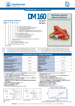
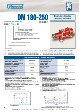
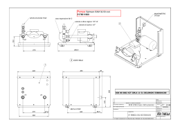
catalogo generale general catalogue DM 180-250 CODICE DI ORDINAZIONE / ORDERING CODE Distributore Idraulico Hydraulic Distributor DM 180-250 P D180 P P 08 4 00 OO = NESSUN OPTIONAL/NO OPTIONALS CO = COPRIMOZZO/PROTECTION CUP RACCORDO D’ENTRATA/INLET GAUGE 4 = 3/4” GAS STANDARD (ATTACCO FEMMINA/FEMALE PORT) 5 = 3/4” GAS (ATTACCO MASCHIO/MALE PORT) 6 = 1” GAS (ATTACCO FEMMINA/FEMALE PORT) 7 = 1” GAS (ATTACCO MASCHIO/MALE PORT) TARATURA VALVOLA MASSIMA PRESSIONE/PRES. RELIEF VALVE SETTING (vedi tabella/see table) P = DISCESA PROGRESSIVA/PROGRESSIVE LOWERING COMANDO PNEUMATICO/PNEUMATIC CONTROL 08 ÷ 35 MPa (80-350 bar) con valvola standard (regolabile)/with standard relief valve (adjustable) 2B con valvola pilotata a 2 livelli (stand. 140, 220 bar)/piloted relief valve with 2 settings 3B con valvola pilotata a 3 livelli (stand. 130, 220, 350 bar)/piloted relief valve with 3 settings 00 senza valvola (predisposto per cartuccia)/without relief valve (suitable for preset cartridge) D0 ÷ D9 con cartuccia regolabile da 10 a 19 MPa/with adjustable cartridge (from 10 to 19 Mpa) E0 ÷ E9 con cartuccia regolabile da 20 a 29 MPa/with adjustable cartridge (from 20 to 29 Mpa) F0 ÷ F5 con cartuccia regolabile da 30 a 35 MPa/with adjustable cartridge (from 30 to 35 Mpa) G0 cartuccia regolabile non tarata, non piombata/not setting, not plumbed adjustable cartridge CARATTERISTICHE TECNICHE / TECHNICAL SPECIFICATIONS Portata nominale - Massima in ingresso Tipping nom. - Max flow rate 180-200 l/min Temperatura fluido °C (t) Fluid temperature °C (t) -25° + 80°C Portata nominale - Massima in scarico Lowering nom. - Max flow rate 250-300 l/min Campo viscosità Viscosity range 12-100 cSt Pressione massima di lavoro Max working pressure 300 bar Filtrazione/Filtering ISO 4406 βx=75 20/17 25 m Pressione massima di picco (<0.1 s) Max peak pressure 450 bar Peso Weight 8-9 kg Pressione massima sul T T port max pressure 30 bar Pressione pneumatica massima Max pneumatic pressure 12 bar > Distributore da 180 l/min (salita) e 250 l/min (discesa), a comando pneumatico, per veicoli ribaltabili con sola motrice (cilindro semplice effetto). > Consente la salita, la discesa veloce e la discesa progressiva. > Sono incorporate di serie la valvola di ritegno in ingresso e la valvola di controllo pressione disponibile in 3 versioni: regolabile, a cartuccia pretarata intercambiabile, pilotata a 2 o 3 livelli di taratura. > Tirante per fine corsa meccanico di serie. > Flangiabile a serbatoio e a telaio. > Attacco manometro o pressostato di serie. > Coprimozzo a richiesta (vedi codifica). > Pneumatic controlled distributor, oil flow 180 l/min (tipping), and 250 l/min (lowering), for tippers without trailer (single-acting cylinder). > It performs tipping, fast and progressive lowering. > The inlet check valve and the relief valve are built-in. Three models of relief valve are available: adjustable relief valve, interchangeable preset cartridge, piloted relief valve with 2 or 3 possible settings. > Standard end-of-stroke rope. > Flange connection to tank and chassis. > Standard pressure-switch or manometer connection. > Protection cup (ordering code). PERDITE DI CARICO / PRESSURE DROP 6 5 ! ΔP (bar) TABELLA/TABLE MODELLO/MODEL 9 8 T) 4 (P 3 (P 2 0 1 100 4 mod. DM 180-250 P › 150 A) 175 200 Q (l/min) 225 250 275 300 RILIEVI ESEGUITI CON OLIO ISO VG 46 A 50° C ( = 30 cSt) THE ABOVE SPECIFICATIONS REFER TO OIL TYPE ISO VG 46 AT 50° C ( = 30 cSt) 92 H YDR OCAR 125 (A T) V ia L e o na r do da V inc i, 19 › 41 0 1 5 N on an t ol a ( M O ) › Tel . + 3 9 0 5 9 8 9 6 1 1 1 › Fax + 3 9 0 5 9 8 9 6 2 0 0 catalogo generale general catalogue VERSIONE STANDARD STANDARD VERSION mod. DM 180-250 P 23 315 !RICHIESTAPRESSOSTATOINTERVENTO¢BAR#OPPIADISERRAGGIO¢.M 5PONREQUESTPRESSURESWITCHSETAT¢BAR4IGHTENINGTORQUE¢.M 162.5 !RICHIESTARACCORDO v' DAv'-ASCHIOO v'&EMMINA VEDICODIFICA 5PONREQUESTCONNECTOR v'-ALEORv'&EMALE SEEORDERINGCODE 120 45 27 Ch 42 Ch 36 54 ! 100 10° 65 = Ch 13 ~85 342 137.5 1”G 75 Ø 13 Ø 60 0 58 Valvola tipo 2B/3B: grano sigillato anti-smontaggio Valve type 2B/3B: antidisassembly grub-screw 20 98 106 44 160 = 4 !RICHIESTA COPRIMOZZOTIPO#/ 5PONREQUEST PROTECTION CUPTYPE#/ Sede OR 147 OR 147 seat 32 65 55 137 22 43 .ª&ORI .O(OLES 17 )NTERCAMBIABILE CON$ )NTERCHANGEABLE WITH$ Valvola tipo 2B/3B: fascetta sigillata rotante Valve type 2B/3B: rotating sealed clip 1/8”G 1/8”G HYDRAULIC DISTRIBUTORS 1”G Per manometro o pressostato For manometer or pressure-switch DISTRIBUTORI IDRAULICI 1/8”G 8 75 9 Ø 62 12 44 20 12 Corse Strokes KIT PER FISSAGGIO AL SERBATOIO / TANK MOUNTING KIT DESCRIZIONE DESCRIPTION CODICE CODE 30KDF02U000 (piastra ≠ 20 mm) Per serbatoio metallico senza piastra For steel tank without flange (plate ≠ 20 mm) 30KDF03U000 (piastra ≠ 30 mm) (plate ≠ 30 mm) Per fissaggio a telaio To fit to chassis 30KFDFU0000 Hydrocar si riserva il diritto di apportare senza alcun preavviso qualsiasi modifica alle caratteristiche tecniche indicate nel presente catalogo. I dati ivi riportati non sono vincolanti. Hydrocar reserves the right to modify the technical data mentioned into this catalogue without notice. The herewith mentioned data are not bounding. 3 93
Scarica