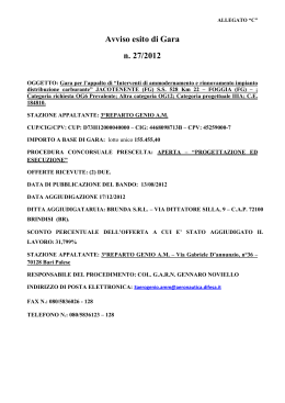
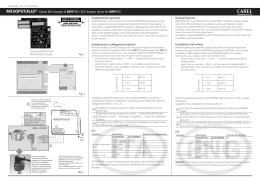
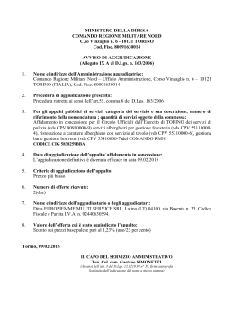
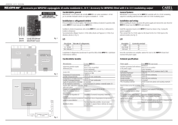
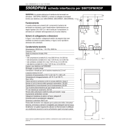
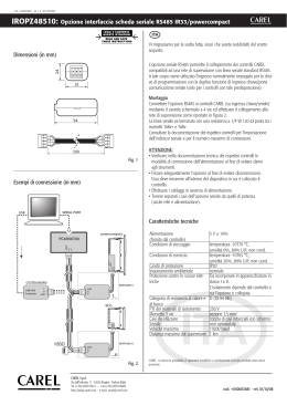
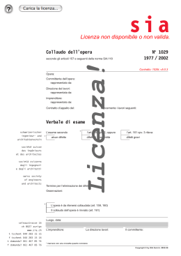
+050000341 - rel.1.4 - 03.06.2009
E2V - Valvola di espansione elettronica / Electronic expansion valve / Soupape à détente électrique / Elektronisches Expansionsventil / Válvula de expansión electrónica
General characteristics
Caratteristiche generali
Per ulteriori informazioni, consultare la “Guida al sistema EEV” (codice
+030220810) disponibile sul sito www.carel.com, alla sezione “documentazione”.
For more information, read the “EEV systems operating manual (code
+030220811) before installing this product. The manual is available in the
“documentation” download area at www.carel.com.
La valvola elettronica E2V è destinata all’installazione in circuiti frigoriferi come dispositivo di espansione per il fluido refrigerante
utilizzando come segnale di regolazione il surriscaldamento calcolato tramite una sonda di pressione ed una di temperatura
poste entrambe all’uscita dell’evaporatore. Per il pilotaggio delle E2V è raccomandato l’uso di strumenti CAREL.
Non utilizzare le valvole E2V al di fuori delle condizioni operative riportate di seguito.
The E2V electronic valve is designed to be installed in refrigerant circuits. The E2V uses the superheat as the control signal which
is calculated by a pressure and temperature probe located at the evaporator outlet.
Only Carel controllers or controllers officially accredited by CAREL are recommended to be used with the E2V valve.
Do not use the E2V outside the normal operating conditions, shown below.
Posizionamento
Positioning
Le valvole E2V essendo bidirezionali possono essere installate con l’ingresso del refrigerante dalla connessione laterale (vedi Fig. 1) o dal
basso.
Installare sempre un filtro meccanico prima dell’ingresso del refrigerante sia con valvole a saldare (E2V*S*) che con valvole a
raccordare (E2V*R*). In questo caso il filtro viene fornito all’interno della confezione.
L’orientamento spaziale è possibile in ogni configurazione tranne che con lo statore rivolto verso il basso (valvola capovolta).
La posizione consigliata della valvola E2V è la stessa della valvola termostatica di tipo tradizionale ossia a monte dell’evaporatore e
dell’eventuale distributore. I sensori di temperatura e pressione (non forniti con le E2V) devono es sere posizionati immediatamente a valle
dell’evaporatore e curando in particolar modo che:
•• il sensore di temperatura sia installato con pasta conduttiva e adeguatamente isolato termicamente;
•• entrambi i sensori siano installati PRIMA di eventuali dispositivi che alterino la pressione (es. valvole) e/o temperatura (es. scambiatori).
Installazione e manipolazione
Le valvole E2V sono a saldare (E2V*S*) o raccordare (E2V*R*).
Per le valvole a saldare seguire la successione indicata in figura procedendo in questo modo:
1. se lo statore è già assemblato, rimuoverlo svitando il dado di fissaggio e sfilandolo;
2. avvolgere uno straccio bagnato sulla valvola e procedere alla saldatura senza surriscaldarla orientando la fiamma verso l’estremità
dei raccordi (per una brasatura saldatura senza alterare la tenuta della zona di saldatura utilizzare lega con temperatura di fusione
inferiore a 650 °C o con tenore d’argento superiore al 25%);
3. a valvola fredda reinserire lo statore e riavvitare il dado di fissaggio;
4. collegare il connettore già cablato al motore passo passo nel relativo alloggiamento e serrare la vite con una coppia massima di 1,5 Nm
seguendo le indicazioni in Fig. 3. Collegare a questo punto l’estremità quadripolare del cavo nei relativi morsetti del Driver CAREL
EVD*** o relativo controllo omologato CAREL ed impostare i parametri secondo il set riportato nella tabella sottostante.
Model
Step min
Step max
step close
Step/s speed
mA pk
mA hold
% duty
CAREL
50
480
500
50
450
100
30
Posizionamento / Positioning
NTC
I controllori Carel per valvola elettronica prevedono l’incremento del duty cycle dal 30% al 100% in fase di chiusura allo scopo di
diminuire i tempi d’arresto; per accelerare ulteriormente questa fase è possibile pilotare la valvola ad una frequenza massima di 150
passi/sec.
Per ulteriori informazioni dei parametri da impostare nel driver, fare riferimento al manuale del controllo.
Per le valvole a raccordare è necessario avvitare gli attacchi al circuito mediante bocchettoni della misura opportuna; poi procedere col
punto 4.
Non esercitare torsioni o deformazioni sulla valvola o sui tubi di collegamento.
Non colpire la valvola con martelli o altri oggetti.
Non utilizzare pinze o altri strumenti che potrebbero deformare la struttura esterna o danneggiare gli organi interni.
Non orientare mai la fiamma verso la valvola.
Non avvicinare la valvola a magneti, calamite o campi magnetici.
Non procedere all’istallazione o all’uso in caso di:
• deformazione o danneggiamento della struttura esterna;
• forte impatto dovuto per esempio a caduta;
• danneggiamento della parte elettrica (statore, portacontatti, connettore,...).
CAREL non garantisce il funzionamento della valvola in caso di deformazione della struttura esterna o danneggiamento delle
parti elettriche.
ATTENZIONE: la presenza di particelle dovute a sporcizia potrebbe causare malfunzionamenti della valvola.
Fig.1
Connessioni elettriche
Collegare un cavo quadripolare al connettore a cablare IP65 (E2VCON*) secondo lo schema sotto riportato: il connettore è di tipo standard
DIN 43650. Eventualmente collegare direttamente un connettore costampato IP67 (E2VCAB0*) la cui mappatura è 1 Verde, 2 Giallo,
3 Marrone, 4 Bianco.
Per le fasi motore si consigliano conduttori AWG18-22 mentre il cavo quadripolare deve avere in diametro esterno da 4 a 6 mm per
consentire un’adeguata presa della guarnizione esterna.
Successivamente collegare le quattro fasi motore al vostro dispositivo driver in modo che la fase n°1 della E2V corrisponda al morsetto n°1
del driver e così via.
Attenzione: la fase n°4 è indicata sullo statore valvola con il simbolo di terra.
È disponibile un connettore costampato schermato opzionale (E2VCABS*) per applicazioni con particolari disturbi elettromagnetici, in
riferimento alla normativa vigente 89/336/CEE e successive modifiche.
Saldatura e manipolazione / Welding and handling
T. Max
650°C
Specifiche operative CAREL E2V
1
2
Compatibilità
R22, R134a, R404A, R407C,R410A, R744, R507A, R417A
Massima Pressione di Lavoro (MOP)
fino a 45 bar (653 psi)
Massimo DP di Lavoro (MOPD)
35 bar (508 psi)
P.E.D.
Gr. 2, art. 3, par. 3
Temperatura refrigerante
-40T65 °C (-40T149 °F)
Temperatura ambiente
-30T50 °C (-22T122 °F)
Contattare CAREL per condizioni operative diverse o refrigeranti alternativi.
3
Statore CAREL E V
2
Statore bipolare in bassa tensione (2 fasi - 24 espansioni polari)
Corrente di fase
Frequenza di pilotaggio
Resistenza di fase (25 °C)
Indice di protezione
Angolo di passo
Avanzamento lineare/passo
Connessioni
Passi di chiusura completa
Passi di regolazione
Fig. 2
450 mA
50 Hz (fino a 150 Hz nel caso di chiusura d’emergenza)
36 Ohm ± 10%
IP65 con E2VCON*, IP67 con E2VCAB*
15 °
0,03 mm (0,0012 inch)
4 fili (AWG 18/22)
500
480
The double-acting E2V valve can be installed with the refrigerant inlet connected to the side or from the bottom (see the Fig. 1).
Always install a mechanical filter before the refrigerant inlet, both with welded valves (E2V*S*) and valves with fittings (E2V*R*).
In this case, the filter is supplied in the package.
The valve can be oriented in any direction, with the exception of the stator pointed downwards, (valve upside down)
The recommended position for the E2V valve is the same as for a traditional thermostatic valve, that is, upstream of the evaporator and any
distributor.
The temperature and pressure sensors (not supplied with the E2V) must be positioned downstream of the evaporator, making sure that:
•• the temperature sensor is installed with conductive paste and is adequately thermally insulated;
•• both sensors are installed BEFORE any devices that may vary the pressure (e.g. valves) and /or temperature (e.g. exchanger).
Installation and handling
The E2V valves have welded connections (E2V*S*) or pipe fittings (E2V*R*).
For the valves with welded connections, follow the steps shown in the figure, proceeding as follows:
1. if the stator is already assembled, remove it by unscrewing the fastening nut and sliding it out;
2. wrap a wet rag around on the valve and perform the welding without overheating the valve, aiming the flame at the ends of the fittings
(for better braze welding without affecting the seal where welding, use alloys with a fusion temperature less than 650 °C or with a silver
content above 25%);
3. when the valve has cooled down insert the stator and retighten the fastening nut.
4. connect the pre-wired connector to the socket on the stepper motor and tighten the screw to a maximum torque of 1.5 Nm following the
instructions in Fig. 3. Connect the four-pin end of the cable to the corresponding terminals on the CAREL EVD*** driver or approved CAREL
controller and set the parameters as shown in the table below.
Model
Min step
Max step
Close step
Speed step/s
mA pk
mA hold
% duty
CAREL
50
480
500
50
450
100
30
Carel controllers for electronic valves increase the duty cycle from 30% to 100% when closing to reduce stopping time; to further speed
up this phase, the valve can be controlled at a maximum frequency of 150 steps/sec.
For further information on the parameters to be set for the driver, see the controller manual.
For valves with compression fittings, tighten the fittings to the circuit using suitably-sized couplings; then proceed from point 4.
Do not twist or strain the valve or the connection pipes.
Do not strike the valve with hammers or other objects.
Do not use pliers or other tools that may deform the external structure or damage the internal parts.
Never point the flame at the valve.
Never bring the valve near magnets or magnetic fields.
Do not install or use the valve in the event of:
• deformation or damage to the external structure;
• heavy impact, for example due to dropping;
• damage to the electrical parts (stator, contact carrier, connector,...).
CAREL does not guarantee the operation of the valve in the event of deformation of the external structure or damage to the
electrical parts.
IMPORTANT: the presence of dirt particles may cause valve malfunctions.
Electrical connections
Connect a four-wire cable to the E2V IP65 cable connector (E2VCON*), according to the diagram shown below: the connector used
complies with the DIN 43650 standard.
Alternatively, use an IP67 co-moulded connector (E2VCAB*), with the following pin configuration: 1 Green, 2 Yellow, 3 Brown, 4 White.
The outside diameter of the four-wire cable must be between 4 and 6 mm to ensure the grip of the external gasket.
Then connect the four phases of the motor to the driver, so that phase 1 of the E2V valve corresponds to terminal 1 on the driver, and so
on.
Warning: phase no. 4 is indicated on the valve stator by the ground symbol.
An optional shielded co-moulded connector is available (E2VCABS*) for applications with considerable electromagnetic disturbance, in
reference to the European directive in force 89/336/EEC and subsequent amendments.
Operating specifications CAREL E2V
Compatibility
R22, R134a, R404A, R407C,R410A, R744, R507A, R417A
Maximum Operating Pressure (MOP)
up to 45 bars (653 psi)
Maximum Operating DP (MOPD)
35 bars (508 psi)
P.E.D.
Gr. 2, art. 3, par. 3
Refrigerant temperature
-40T65°C (-40T149°F)
Room temperature
-30T50°C (-22T122°F)
Contact CAREL for other normal operating conditions or alternative refrigerants.
CAREL stator E2V
Two pole low voltage stator (2 phases - 24 polar shoes)
Phase current
Drive frequency
Phase resistance (25°C / 77°F)
Index of protection
Step angle
Linear advance/step
Connections
Complete closing steps
Control steps
450 mA
50 Hz (up to 150 Hz for emergency closing)
36 Ohm ± 10%
IP65 with E2VCON*, IP67 with E2VCAB*
15 °
0.03 mm (0.0012 inches)
4 wires (AWG 18/22)
500
480
Caractéristiques générales
Connessioni elettriche / Electrical connections
statore
stator
morsettiera
terminal block
scatola connettore
connector case
vite
screw
connettore
E2VCON0000
connector
AWG 18-22
guarnizione
gasket
rondella
washer
CAREL
E2VCAB****
4
Bianco/White
4
2
3
3
1
2
1
vite di chiusura
fastening screw
Giallo/Yellow
Marrone/Brown
Verde/Green
Ø 4-6 mm
Ø 0.16 - 0.24 inch
Fig. 3
Dimensioni in mm (inch)/ Dimensions in mm (inch)
Option 1
E2V**BS*0*
(a saldare)
(to weld)
49.50
B
G
G
D
Ø F In
Ø F In
Ø F Out
G
G
Ø E In
Ø E Out
Ø E In
Ø E thread
Tipo valvola / Valve type
Option 1 E2V**BSF0* rame/copper 12-12 mm ODF
E2V**BSM0* rame/copper 16-16 mm ODF
Option 2 E2V**BRB0* ottone/brass 3/8” - 1/2” SAE
A
124.3 mm
(4.87 inch)
126.3 mm
(4.95 inch)
140.3 mm
(5.5 inch)
B
82.3 mm
(3.28 inch)
84.3 mm
(3.32 inch)
98.3 mm
(3.87 inch)
Tipo valvola / Valve type
E
Option 1 E2V**BSF0* rame/copper 12-12 mm ODF Int. 12/Est. 14 mm
(In 0.47/Out 0.55 inch)
E2V**BSM0* rame/copper 16-16 mm ODF Int.16/Est.18 mm
(In 0.63/Out 0.71 inch)
Option 2 E2V**BRB0* ottone/brass 3/8” - 1/2” SAE Int.9 mm - filett. 3/4”
(In 0.35 inch thread 3/4”)
Die Positionierung des Kältemitteleingangs kann beim bidirektionalen E2V-Ventil von der Seite (siehe Fig. 1)
oder von unten erfolgen. Installieren Sie vor dem Kältemitteleingang immer einen mechanischen Filter
sowohl bei zu lötenden Ventilen (E2V*S*) als auch Ventilen, die mit einem Anschlussstück verbunden
werden.
Der Filter ist bereits in der Packung enthalten.
Die räumliche Ausrichtung ist in jeder Konfiguration, außer mit nach unten gerichtetem Stator, möglich (auf den
Kopf gestelltes Ventil). Die für das E2V-Ventil empfohlene Position ist dieselbe eines traditionellen Thermostatventils, d.h. vor dem Verdampfer und dem eventuellen Verteiler.
Die Temperatur- und Druckfühler (nicht im Lieferumfang enthalten) müssen unmittelbar hinter dem Verdampfer angebracht werden. Achten Sie bitte darauf, dass:
•• der Temperaturfühler mit Wärmeleitpaste installiert und angemessen thermisch isoliert ist;
•• beide Fühler VOR eventuellen Druck-und/oder Temperaturverändernden Vorrichtungen installiert sind (z. B.
Ventile; Tauscher).
Les détendeurs E2V, étant bidirectionnelles, peuvent être installés avec l’entrée du réfrigérant du côté du
raccord latéral (voir Fig. 1) ou par le bas. Installer toujours un filtre mécanique à l’entrée du fluide de
refroidissement autant en présence de soupapes à souder (E2V*S*) qu’avec des soupapes à raccorder
(E2V*R*). Dans ce cas, le filtre est en dotation. L’orientation spatiale est possible pour chaque configuration
exceptée celle avec le stator dirigé vers le bas (détendeur renversé). La position conseillée pour le détendeur
E2V est la même que celle pour le détendeur thermostatique de type traditionnel c’est-à-dire placé avant
l’évaporateur et avant un éventuel distributeur.
Les capteurs de température et de pression (non fournis avec les E2V) doivent être positionnés immédiatement
après l’évaporateur et en faisant particulièrement attention à:
•• ce que le capteur de température soit installé avec la pâte conductrice et qu’il soit isolé thermiquement de
façon appropriée;
•• ce que les deux capteurs soient installés AVANT des dispositifs éventuels pouvant altérer la mesure de
pression (ex. soupapes) et/ou température (ex. échangeurs).
Ø E thread
A
Ø 16
C
Positionnement
Les vannes E2V doivent être soudées (E2V*S*) ou raccordées (E2V*R*).
Pour les vannes à souder respecter l’ordre indiqué sur la figure en procédant comme suit:
1. si le stator est déjà assemblé, le retirer en dévissant l’écrou de fixation et en l’enlevant;
2. enrouler un chiffon mouillé et passer à la soudure sans la surchauffer en orientant la flamme vers l’extrémité des raccords (pour effectuer un soudo-brasage sans altérer l’étanchéité de la zone de soudure, utiliser
un alliage avec une température de fusion inférieure à 650 °C ou une teneur en argent de plus de 25%);
3. réinsérer ensuite le stator une fois que le détendeur est refroidi et revisser l’écrou de fixation.
4. raccorder le connecteur déjà câblé au moteur pas à pas dans le logement correspondant et serrer la vis avec un
couple maximum de 1,5 Nm
en suivant les indications de la Fig. 3. Connecter ensuite l’extrémité quadripolaire du câble aux bornes
correspondantes du Driver CAREL EVD*** ou du contrôle homologué CAREL et configurer les paramètres
selon la valeur reprise au tableau ci-dessous.
44.70
Ø 39
Das elektronische Expansionsventil E2V wird im Kältekreislauf als Entspannungsorgan des
Kältemittels installiert; dabei wird die anhand eines Druck- und Temperaturfühlers am
Verdampferausgang gemessene Überhitzung als Regelsignal verwendet. Für die Steuerung der E2V werden
CAREL-Geräte oder von CAREL offiziell anerkannte Instrumente empfohlen.
Bitte beachten Sie die nachstehend angeführten Betriebsbedingungen.
Installation et manipulation
Option 2
E2V**BRB0*
(a raccordare)
(pipe fittings)
C
52.2 mm
(2.06 inch)
54.2 mm
(2.14 inch)
68.3 mm
(2.69 inch)
F
Int. 12/Est. 14 mm
(In 0.47/Out 0.55 inch)
Int.16/Est.18 mm
(In 0.63/Out 0.71 inch)
Int.9 mm - filett. 5/8”
(In 0.35 inch thread 5/8”)”
Fig. 4
D
53,5 mm
(2,11 inch)
55,5 mm
(2,19 inch)
69,5 mm
(2,74i nch)
G
10 mm
(0.39 inch)
12 mm
(0.47 inch)
24 mm
(0.94 inch)
Model
CAREL
Step min
50
Step max
480
step close
500
Step/s speed
50
mA pk
450
mA hold
100
% duty
30
Les contrôleurs Carel pour détendeur électronique prévoient l’augmentation du cycle de fonctionnement
de 30% à 100% en phase de fermeture dans le but de diminuer les temps d’arrêt; pour accélérer davantage
cette phase, il est possible de piloter la vanne à une fréquence maximale de 150 pas/sec.
Pour plus d’informations sur les paramètres à configurer dans le driver, consulter le manuel du contrôle.
Pour les vannes à raccorder, il faut visser les raccords au circuit au moyen de raccords d’une mesure adéquate,
puis passer au point 4.
Ne pas exercer de torsions ou de déformations sur la soupape ou sur les tubes d’assemblage - Ne pas
taper sur la soupape avec un marteau ou des outils de ce genre - Ne pas utiliser de pinces ou d’autres
instruments qui pourraient déformer la structure externe ou endommager les organes internes - Ne
jamais orienter la flemme en direction de la soupape.
Ne pas approcher des aimants ou des champs magnétiques de la soupape.
Ne pas installer ou utiliser en présence de:
• déformation ou endommagement de la structure externe;
• fort impact dû à une chute par exemple;
• endommagement de la partie électrique (stator, boîtier de contacts, connecteur,...).
CAREL ne garantit pas le fonctionnement de la soupape en cas de déformation de la structure externe ou
en cas d’endommagements des parties électriques.
L’apparecchiatura (o il prodotto) deve essere oggetto di raccolta separata in conformità alle
vigenti normative locali in materia di smaltimento.
Disposal of the product
The appliance (or the product) must be disposed of separately in accordance with the local
waste disposal legislation in force.
The CAREL product is a state-of-the-art product, whose operation is specified in the technical documentation supplied with
the product or can be downloaded, even prior to purchase, from the website www.carel.com.
The client (builder, developer or installer of the final equipment) assumes every responsibility and risk relating to the
phase of configuration the product in order to reach the expected results in relation to the specific final installation and/or
equipment. The lack of such phase of study, which is requested/indicated in the user manual, can cause the final product to
malfunction of which CAREL can not be held responsible. The final client must use the product only in the manner described
in the documentation related to the product itself. The liability of CAREL in relation to its own product is regulated by CAREL’s
general contract conditions edited on the website www.carel.com and/or by specific agreements with clients.
Modell
CAREL
Step min
50
Step max
480
step close
500
Step/s speed
50
mA pk
450
mA hold
100
% duty
30
Die Carel-Steuerungen für das elektronische Ventil sehen die Erhöhung des Duty Cycle von 30% auf 100%
in der Schließungsphase vor, um die Stoppzeiten zu vermindern; für eine zusätzliche Beschleunigung dieser
Phase kann das Ventil auf einer max. Frequenz von 150 Schritt/Sek. gesteuert werden.
Für weitere Informationen über die im Treiber einzustellenden Parameter siehe das technische Handbuch
der Steuerung.
Für die anzuschließenden Ventile müssen die Anschlüsse an den Kreis mit angemessen großen Stutzen
verschraubt werden; fahren Sie mit Punkt 4 fort.
Achten Sie darauf, dass das Ventil oder die Anschlussleitungen nicht Drehungen oder Verformungen
ausgesetzt sind. Schlagen Sie auf das Ventil nicht mit Hammer oder anderen Gegenständen ein. Benutzen
Sie nicht Zangen oder andere Werkzeuge, welche die Außenstruktur verformen oder die internen Organe
beschädigen könnten. Richten Sie die Flamme nie auf das Ventil. Bringen Sie das Ventil nie in die Nähe
von Magneten oder Magnetfeldern. Installieren oder benutzen Sie das Ventil nie bei:
• Verformung oder Beschädigung der Außenstruktur;
• starkem Aufprall, z. B. nach einem Fall;
• Beschädigung des elektrischen Teils (Stator, Kontakthalter, Steckverbinder,...).
CAREL haftet im Fall einer Verformung der Außenstruktur oder Beschädigung der elektrischen Teile nicht
für den korrekten Betrieb des Ventils.
Las válvulas E2V, al ser bidireccionales, se pueden instalar con la entrada refrigerante por la conexión lateral
(véase la Fig. 1) o desde abajo. Instalar siempre un filtro mecánico antes de la entrada del refrigerante,
tanto con válvulas para soldar (E2V*S*) como con válvulas para empalmar (E2V*R*). En este caso el filtro
se suministra en el interior del empalme.
La orientación espacial resulta posible en cualquier configuración excepto con el estátor dirigido hacia abajo
(válvula invertida). La posición aconsejada de la válvula E2V es la misma que para una válvula termostática de
tipo tradicional; es decir antes del evaporador y del eventual distribuidor. Los sensores de temperatura y presión
(que no se entregan con las E2V) se deben posicionar inmediatamente antes del evaporador y cuidando de
forma especial que:
•• el sensor de temperatura se instale con pasta conductora y se haya aislado térmicamente de forma
adecuada;
•• ambos sensores se hayan instalado ANTES de cualquier dispositivo que altere la presión (por ejemplo, válvulas) y/o la temperatura (por ejemplo intercambiadores).
Instalación y manipulacion
Las válvulas E2V se deben soldar (E2V*S*) o empalmar (E2V*R*).
Para las válvulas que se deben soldar seguir las instrucciones indicadas en la figura, procediendo de la siguiente
forma:
1. Si el Actuador está ya montado, quitarlo desenroscando el dado de fijación y soltándolo;
2. Enrollar un trapo mojado y proceder a realizar la soldadura, sin recalentarla, orientando la llama hacia el extremo de las piezas de unión (para una soldadura mejor sin alterar la estanqueidad de la zona de soldadura
utilizar aleación con temperatura de fusión inferior a 650 °C ó con contenido de plata superior al 25%);
3. Con la válvula fría volver a introducir el Actuador y a atornillar la tuerca de fijación.
4. Conectar el conector ya cableado al motor de pasos en el alojamiento correspondiente y apretar el tornillo con
un par máximo de 1,5 Nm siguiendo las indicaciones de la Fig. 3. Conectar en este punto el extremo cuadripolar del cable en los terminales correspòndientes del Driver CAREL EVD***, u otro control homologado
por CAREL, y configurar los parámetros según se indica en la tabla siguiente.
Modelo
CAREL
Step min
50
Step max
480
step close
500
Step/s speed
50
mA pk
450
mA hold
100
% duty
30
Los controladores Carel para válvula electrónica prevén el incremento del duty cycle del 30% al 100%
en fase de cierre con el fin de disminuir los tiempos de parada; para acelerar posteriormente esta fase es
posible controlar la válvula a una frecuencia máxima de 150 pasos/seg.
Para más información sobre los parámetros a configurar en el, consultar el manual del controlador.
Para las válvulas de roscar es necesario enroscar los adaptadores al circuito mediante boquillas de la medida
adecuada; después prodecer con el punto 4.
No aplicar torsiones o deformaciones en la válvula o en los tubos de conexión - No golpear la válvula
con martillos u otros objetos - No utilizar pinzas u otras herramientas que podrían deformar la estructura
externa o estropear los componentes internos - Nunca dirigir la llama hacia la válvula.
No acercar la válvula a magnetos, imanes, o campos magnéticos.
No proceder a la instalación o a la utilización en caso de:
• deformación o daños de la estructura interna;
• fuerte impacto debido por ejemplo a caída;
• daños de la parte eléctrica (estator, portacontactos, conector,...).
CAREL no garantiza el funcionamento de la válvula en caso de deformación de la estructura externa o de
daños en las partes electricas.
Connexions Electriques
Elektrische Anschlüsse
Schließen Sie ein vierpoliges Kabel an den Steckverbinder IP65 (E2VCON*) E2V nach dem unten abgebildeten
Schema an. Der Steckverbinder besitzt den Standard DIN 43650. Schließen Sie eventuell einen Stecker für
Extrembedingungen IP67 (E2VCAB*) direkt an (Farbübersicht: 1 Grün, 2 Gelb, 3 Braun, 4 Weiß). Als Kabelquerschnitt wird AWG18-22 empfohlen, während das vierpolige Kabel einen Außendurchmesser von 4 bis 6
mm haben muss, damit die externe Dichtung ihre Funktion erfüllen kann. Schließen Sie anschließend die vier
Phasen an Ihren Treiber an, damit die Phase 1 des E2V der Klemme 1 des Treibers entspricht etc.
Achtung: die Phase 4 ist auf dem Ventilstator mit dem Erdungssymbol angegeben.
Es ist ein optionaler Stecker für Extrembedingungen mit Schirm (E2VCABS*) für Anwendungen mit besonderen
elektromagnetischen Störungen verfügbar. Unter Bezugnahme auf die geltende Gesetzgebung 89/336/CEE und
nachfolgende Änderungen.
Conexiones eléctricas
Connecter un câble quadripolaire au connecteur à câbler IP65 (E2VCON*) E V suivant le schéma reporté
ci-dessous: le connecteur est du type standard DIN 43650.
Éventuellement connecter directement un connecteur co-moulé IP67 (E2VCAB*) dont le schéma correspond à
1 Vert, 2 Jaune, 3 Marron, 4 Blanc. Pour les phases du moteur, les conducteurs AWG18-22 sont conseillés alors
qu’un câble quadripolaire doit avoir un diamètre externe de 4 à 6 mm pour permettre une prise adaptée du
joint externe. Puis, relier les quatre phases du moteur à votre dispositif pilote de façon à ce que la phase n°1 de
la E2V corresponde à la borne n°1 du pilote et ainsi de suite.
Attention: la phase n°4 est indiquée sur le stator de la soupape avec le symbole de la terre. Un connecteur
co-moulé blindé est disponible comme option (E2VCABS*) pour des applications présentant des brouillages
électromagnétiques particuliers. Norme référentielle en vigueur 89/336/CEE et modifications successives.
Compatibilité
R22, R134a, R404A, R407C,R410A, R744, R507A, R417A
Pression d’exercice maximale (MOP)
jusqu’à 45 bar (653 psi)
Pression d’exercice maximale (MOPD)
35 bar (508 psi)
P.E.D.
Gr. 2, art. 3, par. 3
Température du réfrigérant
-40T65 °C (-40T149 °F)
Température ambiante
-30T50 °C (-22T122 °F)
Contacter CAREL pour des conditions opérationnelles différentes ou Réfrigérants alternatifs.
Stator CAREL E2V
Courant de phase
Fréquence de pilotage
Résistance de phase (25 °C)
Index de protection
Angle de pas
Avancement linéaire/pas
Connexions
Pas de fermeture complète
Pas de réglage
CAREL INDUSTRIES - HQs
Via dell’Industria, 11 - 35020 Brugine - Padova (Italy) - Tel. (+39) 049.9716611
Fax (+39) 049.9716600 - e-mail: [email protected] - www.carel.com
Betriebsbedingungen CAREL E2V
Kompatibiltät
R22, R134a, R404A, R407C,R410A, R744, R507A, R417A
Max. Betriebsdruck (MOP)
bis zu 45 bar (653 psi)
Max. Betriebs- ¢P (MOPD)
35 bar (508 psi)
P.E.D.
Gr. 2, art. 3, par. 3
Temperatur des Kältemittels
-40T65 °C (-40T149 °F)
Umgebungstemperatur
-30T50 °C (-22T122 °F)
Kontaktieren Sie CAREL bei hiervon abweichenden Betriebsbedingungen oder verschiedene kühefeüssigkeit.
Stator CAREL E2V
Zweipoliger Niederspannungsstator (2 Phasen - 24 Polschuhe)
Stator bipolaire en basse tension (2 phases - 24 détentes polaires)
IMPORTANT WARNINGS
Die E2V-Ventile müssen gelötet (E2V*S*) oder mit Anschlussstück verbunden werden (E2V*R*). Befolgen Sie
beim Verlöten die in der Abbildung dargestellten und nachstehend angeführten Schritte:
1. Ist der Stator bereits montiert, lockern Sie die Sicherungsmutter und nehmen Sie ihn ab.
2. Wickeln Sie einen nassen Lappen um das Ventil und schweißen Sie, ohne das Ventil selbst zu
überhitzen; richten Sie die Flamme auf die Enden der Anschlussstücke (für eine bessere Verlötung ohne
Beeinträchtigung der Lötstellen sollte eine Legierung mit Schmelztemperatur unter 650 °C oder mit
Silbergehalt über 25% verwendet werden).
3. Lassen Sie das Ventil abkühlen, setzen Sie anschließend den Stator auf und schrauben Sie die
Sicherungsmutter wieder fest.
4. Schließen Sie den vorverdrahteten Steckverbinder an den Schrittmotor an und drehen Sie die Schraube nach
den Anleitungen der Fig. 3 mit rund 1,5 Nm Drehmoment zu. Schließen Sie das Vierleiterkabelende an die
entsprechenden Klemmen des CAREL-Treibers EVD*** oder an eine andere zulässige CAREL-Steuerung an
und stellen Sie die Parameter gemäß nachstehender Tabelle ein.
Posicionamiento
ATENCIÓN: la presencia de partículas debidas a suciedad podrían causar malos funcionamientos
de la válvula.
Spécifications opérationnelles CAREL E V
Il prodotto CAREL è un prodotto avanzato, il cui funzionamento è specificato nella documentazione tecnica fornita col
prodotto o scaricabile, anche anteriormente all’acquisto, dal sito internet www.carel.com.
Il cliente (costruttore, progettista o installatore dell’equipaggiamento finale) si assume ogni responsabilità e rischio in
relazione alla fase di configurazione del prodotto per il raggiungimento dei risultati previsti in relazione all’installazione e/o
equipaggiamento finale specifico.
La mancanza di tale fase di studio, la quale è richiesta/indicata nel manuale d’uso, può generare malfunzionamenti nei
prodotti finali di cui CAREL non potrà essere ritenuta responsabile. Il cliente finale deve usare il prodotto solo nelle modalità
descritte nella documentazione relativa al prodotto stesso. La responsabilità di CAREL in relazione al proprio prodotto è
regolata dalle condizioni generali di contratto CAREL editate nel sito www.carel.com e/o da specifici accordi con i clienti.
Installation und Handhabung
La válvula electrónica E2V se ha destinado a la instalación en circuitos frigoríficos como dispositivo
de expansión para el fluido refrigerante, utilizando como señal de regulación el recalentamiento
calculado mediante una sonda de Presión y una de Temperatura, situadas ambas a la salida del evaporador.
Para el control de las E2V se recomienda utilizar instrumentos CAREL o acreditados oficialmente por la misma
CAREL.
No utilizar las válvulas E2V fuera de las condiciones operativas que se indican a continuación.
ACHTUNG: Vorhandene Schmutzteilchen könnten Funktionsstörungen am Ventil hervorrufen.
2
AVVERTENZE IMPORTANTI
Positionierung
Características generales
ATTENTION: La présence de particules dues à des saletés pourrait causer des dysfonctionnements
de la vanne.
2
Smaltimento del prodotto
Allgemeine Merkmale
Le détendeur électronique E2V est destiné a être installé dans les circuits frigorifiques comme
dispositif à détente pour le liquide réfrigérant en utilisant comme signal de réglage la surchauffe
calculée au moyen d’une sonde de pression et de température situées à la sortie de l’évaporateur. L’utilisation
des instruments CAREL ou bien l’utilisation des instruments approuvés par CAREL même est recommandée
pour le pilotage des E2V.
Ne pas utiliser les détendeurs E2V pour d’autres utilisations opérationnelles que celles reportées ci-après.
450 mA
50 Hz (jusqu’à 150 Hz dans le cas de fermeture d’urgence)
36 Ohm ± 10%
IP65 avec E2VCON*, IP67 avec E2VCAB*
15°
0,03 mm (0,0012 inch)
4 fils (AWG 18/22)
500
480
Phasenstrom
Steuerfrequenz
Phasenwiderstand 25 °C
Schutzart
Schrittwinkel
Linearer Vorschub/Schritt
Anschlüsse
Schritte für vollständige Schließung
Regelschritte
450 mA
50 Hz (bis zu 150 Hz im Fall der Notschließung)
36 Ohm ± 10%
IP65 mit E2VCON*, IP67 mit E2VCAB*
15°
0,03 mm (0,0012 inch)
4 Drähte (AWG 18/22)
500
480
Conectar un cable cuadripolar al conector que se debe cablear IP65 (E2VCON*) E2V siguiendo el esquema que
se encuentra a continuación: el conector es de tipo estándar DIN 43650. Si necesario conectar directamente un
conector coimprimido IP67 (E2VCAB*) cuyo mapeo es 1 Verde, 2 Amarillo, 3 Marrón, 4 Blanco. Para las fases
del motor se aconsejan conductores AWG18-22, mientras que el cable cuadripolar debe tener un diámetro
externo de 4 a 6 mm, para permitir un adecuado agarre de la junta externa. A continuación conectar las cuatro
fases del motor al dispositivo controlador con el fin de que la fase número 1 de la E2V corresponda al borne
número 1 del controlador, y así sucesivamente.
Atención: la fase número 4 se indica en el estátor de la válvula con el símbolo de toma de tierra.
Hay disponible un conector co-moldeado blindado opcional (E2VCABS*) para aplicaciones con perturbaciones electromagnéticas particulares, en cumplimiento de la normativa vigente 89/336/CEE y modificaciones
posteriores.
Especificaciones operativas CAREL E2V
Compatibilidad
R22, R134a, R404A, R407C,R410A, R744, R507A, R417A
Máxima Presión de trabajo (MOP)
hasta los 45 bar (653 psi)
Máximo DP de trabajo (MOPD)
35 bar (508 psi)
P.E.D.
Gr. 2, art. 3, par. 3
Temperatura refrigerante
-40T65 °C (-40T149 °F)
Temperatura ambiente
-30T50 °C (-22T122 °F)
Ponerse en contacto con CAREL para diferentes condiciones operativas o refrigerantes altenativos.
Estátor CAREL E2V
Estátor bipolar de baja tensión (2 fases – 24 expansiones polares)
Corriente de fase
Frecuencia de control
Resistencia de fase (25°C)
Índice de protección
Ángulo de paso
Avance lineal/paso
Conexiones
Pasos de cierre completo
Pasos de regulación
450 mA
50 Hz (hasta 150 Hz en el caso de cierre de emergencia)
36 Ohm ± 10%
IP65 con E2VCON*, IP67 con E2VCAB*
15°
0,03 mm (0,0012 pulgadas)
4 hilos (AWG 18/22)
500
480
CAREL si riserva la possibilità di apportare modifiche o cambiamenti ai propri prodotti senza alcun preavviso / CAREL reserves the right to modify the features of its products without prior notice
+050000341 - rel.1.4 - 03.06.2009
Scaricare