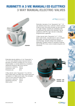
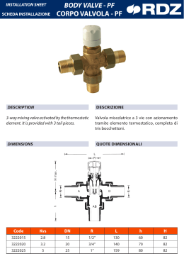
VALVOLE DI RITEGNO E DI FONDO: EUROPA®
CHECK AND FOOT VALVES: EUROPA®
CATALOGO TECNICO
TECHNICAL CATALOGUE
Valvola di ritegno EUROPA®
EUROPA® check valve
100
Voci di capitolato - Technical features
Corpo in ottone.
Tenuta in acciaio inox.
Guarnizione in NBR.
Molla in acciaio inox.
Temperature minima e massima di esercizio: -20°C, 100°C.
Attacchi filettati ISO228 (equivalente a DIN EN ISO 228 e BS EN ISO 228).
Body in brass.
Plate in stainless steel.
Washer in NBR.
Spring in stainless steel.
Minimum and maximum working temperatures: -20°C, 100°C.
Threads: ISO228 (equivalent to DIN EN ISO 228 and BE EN ISO 228).
misura/size
3/8" (DN 10)
1/2" (DN 15)
3/4" (DN 20)
1" (DN 25)
1"1/4 (DN 32)
1"1/2 (DN 40)
2" (DN 50)
2"1/2 (DN 65)
3" (DN 80)
4" (DN 100)
pressione/pressure
25bar/362.5psi
25bar/362.5psi
25bar/362.5psi
25bar/362.5psi
18bar/261psi
18bar/261psi
18bar/261psi
12bar/174psi
12bar/174psi
12bar/174psi
codice/code
1000038
1000012
1000034
1000100
1000114
1000112
1000200
1000212
1000300
1000400
imballo/packing
10/170
10/170
8/120
6/78
4/48
4/36
2/24
1/12
1/8
1/5
Scheda materiali - Materials
1
2
3
pos.
descrizione/description
q.tà/n.
materiale/material
1
Corpo/ Body
1
Ottone stampato/ Hot pressed brass
CW617N
4
2
Perno/ Pin
1
Ottone/ Brass CW614N
3
Molla/ Spring
1
Acciaio/ AISI 302
5
4
Tenuta/ Plate
1
Acciaio/ AISI 304
5
Guarnizione/ Washer
1
NBR
6
Tappo/ Plug
1
Ottone/ Brass CW614N
7
Manicotto/ End adapter
1
Ottone stampato/ Hot pressed brass
CW617N
6
7
Certificazioni- Certifications
Quote di ingombro - Drawing
A
B
misure / size
3/8”
1/2”
3/4”
1”
1”1/4
1”1/2
2”
2”1/2
3”
4”
A (mm)
55
58,5
65
74,5
83
93
101
122
141,5
158,5
B (mm)
34,5
34,5
41,5
48
60,5
71
87
120
140,5
172,5
press. atmosf./ work. press.
Kg/cm2 - bar
25
25
25
25
18
18
18
12
12
12
press. atmosf. psi
lbs work. press
360
360
360
360
260
260
260
170
170
170
Installazione - Manufacturer’s instructions
Installazione
Le valvole EUROPA® sono unidirezionali; permettono cioè il passaggio del fluido in una sola direzione, esse vanno quindi montate in modo che la frecciasul corpo sia nella stessa direzione del
fluido. Le valvole sono composte da una molla, un valvolina e due
parti di ottone, corpo e manicotto, che le contengono e che sono
assemblate fra loro tramite una filettatura e sigillate tramite apposito frena-filetti. Per avitare che lo strato di frena-filetti si rompa e
quindi che la valvola perda dall’accoppiamento corpo-manicotto,
bisogna evitare di sottoporre le due parti a momenti torcenti. Per
la loro installazione vanno utilizzate le normale pratiche idrauliche, ed in particolare:
Installation
The EUROPA® check valves are uni-directional; in the sense that
they manage the flow in one direction only, which is indicated
by the arrow on the body. The valves are composed by a spring,
a little valve and a couple of parts made of brass (body and endadapter) which contain them and that are assembled bt means
of threat and a sealed material to obtain their aim. In order to
avoid that the sealed material gets broken and then the valve looses the connection between the body and the end-adapter, it’s
necessary to avoid to submit the two parts under the influence
of a torque. For the installation normal hydraulic practices must
be used, and especially:
- assicurarsi che le due tubature siano correttamente allineate;
- The installer has to be sure that the two pipes are correctly allied;
- durante il montaggio applicare la chiave all’estremità della valvola più vicina al tubo;
- l’applicazione del materiale di fissaggio (PTFE, canapa) deve essere limitato alla zona del filetto, un eccesso potrebbe inteferire
nella zona di tenuta gomma-metallo pregiudicanzo la funzionalità della valvola;
- nel caso in cui il fluido presenti delle impurità (sporco, polvere,
eccessiva durezza dell’acqua) queste vanno rimosse o filtrate perchè potrebbero interferire nella zona di tenuta gomma-metallo
pregiudicando la funzionalità della valvola.
Disinstallazione
Per la disinstallazione della valvola dalla linea o comunque prima
di svitare le giunzioni ad essa collegate: indossare gli indumenti
protettivi normalmente richiesti per lavorare con il fluido contenuto nella linea;
depressurizzare la linea;
durante lo smontaggio applicare la chiave al’’estremità della valvola più vicina al tubo.
Manutenzione
Verificare la valvola periodicamente, in funzione dell’utilizzo e delle condizioni di lavoro, per assicurarsi che funzioni correttamente. In caso ci siano delle perdite in corrispondenza della tenuta,
queste possono essere causate dal deposito di qualche corpo
estraneo (sporco, calcare) sulla tenuta in gomma. Per rimediare
a questo inconveniente, smontare la valvola e rimuovere il corpo
estraneo tramite aria compressa o utensili.
- During the assembling process the installer has to apply its assembling tools at the end that is nearest to the pipe;
- The application of the sealing materials by the fitter (PTFE or
hempen cloth) must be limited at the threat zone. An excess
should interfere in the ball gas get’s closure zone, compromising
the tightness;
-In case the fluid transported has got some impurities (dust, too
hard water, and so on) it’s necessary to remove impurities by or
filter them, otherwise they could damage the seal.
Disassembly the installed valve
To remove the valve from the pipe line or anyhow before unscrewing the connections linked:
- Wear the protective clothing normally required to work with carried fluids;
- Take the prerssure inside the line out;
-During the disassembling process, apply the key at the end of
the valve, the one nearest the pipe
Maintenance
Verify the valve periodically, according to its application’s field and
its works’ field and its work’s conditions, in order to be sure that
the valve works correctly. In case of losses of tightening, take note
that these can be caused by a deposit of foreign bodies (dirty,
calcareous) on the rubber seal. In order to solve this inconvenient,
it’s necessary to unmount the valve and remove the foreign body
with compressed air tools.
Diagramma perdite di carico - Loss diagram
misure / size
3/8”
1/2”
3/4”
1”
1”1/4
1”1/2
2”
2”1/2
3”
4”
Kv
2,99
4,12
7,03
11,45
16,54
24,12
39,32
70,64
105,60
155,30
Con acqua - With water
Dati forniti dal laboratorio CETIM accreditato da RNE - Dates given by laboratory CETIM acrredited by RNE
Diagramma apertura valvola - Diagram minimum pressure to get the valves opening
Dp= Pin-Pout
(mbar)
110
100
90
The opening of the valve is
givenby the different pressure
between the two sides of the
seat
80
70
1”
3/4
1/
2
” 1”
60
1/2
”
50
Xi
1”
1/
40
Opening = X1-X0
t
4
3/8
”-
X
=
X1
hu
S
0=
en
Op
Dpi
/2
2”1
2”
30
3”
20
4”
10
0
X
Course
(mm)
0
5
10
15
20
25
30
35
40
45
Valvola di fondo EUROPA®
EUROPA® foot valve
105
Voci di capitolato - Technical features
Corpo in ottone.
Tenuta in acciaio inox.
Guarnizione in NBR.
Molla in acciaio inox.
Filtro in polimero e acciaio inox.
Grado di filtrazione: da 3/8” a 2”: 1200 µm; da 2”1/2 a 4”: 2000 µm.
Temperature minima e massima di esercizio: -20°C, 100°C.
Attacchi filettati ISO228 (equivalente a DIN EN ISO 228 e BS EN ISO 228).
Body in brass.
Plate in stainless steel.
Washer in NBR.
Spring in stainless steel.
Strainer in polymer and stainless steel.
Filtration degree: 3/8” trhough 2”: 1200 µm; 2”1/2 through 4”: 2000 µm.
Minimum and maximum working temperatures: -20°C, 100°C.
Threads: ISO228 (equivalent to DIN EN ISO 228 and BE EN ISO 228).
misura/size
3/8" (DN 10)
1/2" (DN 15)
3/4" (DN 20)
1" (DN 25)
1"1/4 (DN 32)
1"1/2 (DN 40)
2" (DN 50)
2"1/2 (DN 65)
3" (DN 80)
4" (DN 100)
pressione/pressure
25bar/362.5psi
25bar/362.5psi
25bar/362.5psi
25bar/362.5psi
18bar/261psi
18bar/261psi
18bar/261psi
12bar/174psi
12bar/174psi
12bar/174psi
codice/code
1050038
1050012
1050034
1050100
1050114
1050112
1050200
1050212
1050300
1050400
imballo/packing
8/160
8/160
6/114
4/76
4/48
2/36
2/20
1/9
1/6
1/5
Scheda materiali - Materials
1
2
3
4
pos.
5
1
Corpo/ Body
1
Ottone stampato/ Hot pressed brass
CW617N
6
2
Perno/ Pin
1
Ottone/ Brass CW614N
7
3
Molla/ Spring
1
Acciaio/ AISI 302
4
Tenuta/ Plate
1
Acciaio/ AISI 304
5
Guarnizione/ Washer
1
NBR
6
Tappo/ Plug
1
Ottone/ Brass CW614N
7
Manicotto/ End adapter
1
Ottone stampato/ Hot pressed brass
CW617N
8
Manicotto/ End adapter
1
Polimero / Polymer
9
Filtro/ Strainer
1
Acciaio/ AISI 304
8
9
Certificazioni- Certifications
descrizione/description
q.tà/n.
materiale/material
Quote di ingombro - Drawing
B
EUROPA
1 ,,
PATENTED
BREVETTATO
A
MADE IN ITALY
misure / size
3/8”
1/2”
3/4”
1”
1”1/4
1”1/2
2”
2”1/2
3”
4”
A (mm)
90
97,5
114
132,5
147
165
187
230
264,5
296
B (mm)
34,5
34,5
41,5
48
60,5
61
87
120
140,5
172,5
press. atmosf./ work. press.
Kg/cm2 - bar
25
25
25
25
18
18
18
12
12
12
press. atmosf. psi
lbs work. press
360
360
360
360
260
260
260
170
170
170
Installazione - Manufacturer’s instructions
Installazione
Le valvole EUROPA® sono unidirezionali; permettono cioè il passaggio del fluido in una sola direzione, esse vanno quindi montate in modo che la frecciasul corpo sia nella stessa direzione del
fluido. Le valvole sono composte da una molla, un valvolina e due
parti di ottone, corpo e manicotto, che le contengono e che sono
assemblate fra loro tramite una filettatura e sigillate tramite apposito frena-filetti. Per avitare che lo strato di frena-filetti si rompa e
quindi che la valvola perda dall’accoppiamento corpo-manicotto,
bisogna evitare di sottoporre le due parti a momenti torcenti. Per
la loro installazione vanno utilizzate le normale pratiche idrauliche, ed in particolare:
Installation
The EUROPA® check valves are uni-directional; in the sense that
they manage the flow in one direction only, which is indicated
by the arrow on the body. The valves are composed by a spring,
a little valve and a couple of parts made of brass (body and endadapter) which contain them and that are assembled bt means
of threat and a sealed material to obtain their aim. In order to
avoid that the sealed material gets broken and then the valve looses the connection between the body and the end-adapter, it’s
necessary to avoid to submit the two parts under the influence
of a torque. For the installation normal hydraulic practices must
be used, and especially:
- assicurarsi che le due tubature siano correttamente allineate;
- The installer has to be sure that the two pipes are correctly allied;
- durante il montaggio applicare la chiave all’estremità della valvola più vicina al tubo;
- l’applicazione del materiale di fissaggio (PTFE, canapa) deve essere limitato alla zona del filetto, un eccesso potrebbe inteferire
nella zona di tenuta gomma-metallo pregiudicanzo la funzionalità della valvola;
- nel caso in cui il fluido presenti delle impurità (sporco, polvere,
eccessiva durezza dell’acqua) queste vanno rimosse o filtrate perchè potrebbero interferire nella zona di tenuta gomma-metallo
pregiudicando la funzionalità della valvola.
Disinstallazione
Per la disinstallazione della valvola dalla linea o comunque prima
di svitare le giunzioni ad essa collegate: indossare gli indumenti
protettivi normalmente richiesti per lavorare con il fluido contenuto nella linea;
depressurizzare la linea;
durante lo smontaggio applicare la chiave al’’estremità della valvola più vicina al tubo.
Manutenzione
Verificare la valvola periodicamente, in funzione dell’utilizzo e delle condizioni di lavoro, per assicurarsi che funzioni correttamente. In caso ci siano delle perdite in corrispondenza della tenuta,
queste possono essere causate dal deposito di qualche corpo
estraneo (sporco, calcare) sulla tenuta in gomma. Per rimediare
a questo inconveniente, smontare la valvola e rimuovere il corpo
estraneo tramite aria compressa o utensili.
- During the assembling process the installer has to apply its assembling tools at the end that is nearest to the pipe;
- The application of the sealing materials by the fitter (PTFE or
hempen cloth) must be limited at the threat zone. An excess
should interfere in the ball gas get’s closure zone, compromising
the tightness;
-In case the fluid transported has got some impurities (dust, too
hard water, and so on) it’s necessary to remove impurities by or
filter them, otherwise they could damage the seal.
Disassembly the installed valve
To remove the valve from the pipe line or anyhow before unscrewing the connections linked:
- Wear the protective clothing normally required to work with carried fluids;
- Take the prerssure inside the line out;
-During the disassembling process, apply the key at the end of
the valve, the one nearest the pipe
Maintenance
Verify the valve periodically, according to its application’s field and
its works’ field and its work’s conditions, in order to be sure that
the valve works correctly. In case of losses of tightening, take note
that these can be caused by a deposit of foreign bodies (dirty,
calcareous) on the rubber seal. In order to solve this inconvenient,
it’s necessary to unmount the valve and remove the foreign body
with compressed air tools.
Diagramma apertura valvola - Diagram minimum pressure to get the valves opening
Dp= Pin-Pout
(mbar)
110
100
90
The opening of the valve is
givenby the different pressure
between the two sides of the
seat
80
70
1”
3/4
1/
2
” 1”
60
1/2
”
50
Xi
1”
1/
40
Opening = X1-X0
t
4
3/8
”-
X
=
X1
hu
S
0=
en
Op
Dpi
/2
2”1
2”
30
3”
20
4”
10
0
X
Course
(mm)
0
5
10
15
20
25
30
35
40
45
Scarica