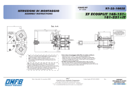
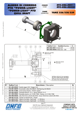
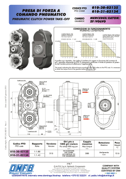
ISTRUZIONI PER IL MONTAGGIO
PTO “HIGH POWER”
CODICE FAMIGLIA
FAMILY CODE
HIGH POWER PTO
MOUNTING INSTRUCTIONS
CAMBIO
GEARBOX
10-47/48
49/50/57/58
ZF AS-TRONIC
KIT: 093-010-47016
2x 9
8
1
2
3x 3
7
4
3x 6
5x 5
Codice foglio:997-001-01195 Rev: AB
Data: Venerdì 15 ottobre 2010
1) Nel caso in cui le teste dei 4 bulloni di fissaggio
fra flangia uscita cambio e giunto cardanico siano
rivolte verso il differenziale, questi devono essere
invertiti in modo che le teste siano rivolte verso il
cambio.
./
Differenziale
Differential
If the fastening bolts between the gear output flange and
the universal joint are directed towards the differential
gear, they must be inverted so that the heads are directed
towards the gearbox.
2) Smontare il coperchio posteriore originale e rimuovere eventuali tracce di pasta/prodotto sigillante e di vernice. N.B.: rimuovere il tappo filettato
M10x1 CH 5 predisposto per la lubrificazione (evidenziato in figura). Rimuovere i tappi in plastica di
protezione dei fori M12 sul piano del cambio.
Take out the original rear cover and remove any presence
of sealant or painting. PS: to ensure a proper PTO lubrication, please remove the plug M10x1 CH 5 from the gearbox. (Highlighted in the figure)
Remove the plastic protective caps from the M12 holes on
the gear surface.
3) Montare OR (4) + tappo forato (1) + OR (2) al
posto del tappo rimosso nel punto 2.
Mount OR (4) + pierced cap (1) + OR (2) in place of the
cap removed in point 2.
pag.1
O.M.F.B. S.p.A. Hydraulic Components
We reserve the right to make any changes without notice.
Edition 2007.10 No reproduction, however partial, is permitted.
Via Cave, 7/9 25050 Provaglio d’Iseo (Brescia) Italy Tel.: +39.030.9830611
Fax: +39.030.9839207-208 Internet:www.omfb.it e-mail:[email protected]
9%3
Cambio
Gearbox
ZF AS-TRONIC
ISTRUZIONI PER IL MONTAGGIO PTO “HIGH POWER”
HIGH POWER PTO MOUNTING INSTRUCTIONS
10-47/48
10-49/50/57/58
4) Inserire l’albero pos.7 completo di cuscinetto.
Fit the shaft (7) complete with bearing.
5) Montare il distanziale pos.8.
Mount the pos. 8 spacer.
6) Smontare coperchio della PTO con chiave a brugola CH 6.
Verificare che gli OR siano saldamente in sede.
7) Montare i 3 OR mantenendoli in sede con del
grasso.
Nota: lasciare libero il foro filettato di lubrificazione.
(evidenziato in figura).
Mount the 3 OR, keeping them in position with grease.
N.B. do not lubricate the threaded hole. (highlighted in
the figure).
8) Montare la PTO sul cambio.
Mount the PTO on the gear.
pag.2
O.M.F.B. S.p.A. Hydraulic Components
We reserve the right to make any changes without notice.
Edition 2007.10 No reproduction, however partial, is permitted.
Via Cave, 7/9 25050 Provaglio d’Iseo (Brescia) Italy Tel.: +39.030.9830611
Fax: +39.030.9839207-208 Internet:www.omfb.it e-mail:[email protected]
Codice foglio:997-001-01195 Rev: AB
Data: Venerdì 15 ottobre 2010
Remove the cover of the PTO with allen wrench CH6. Check that the OR are securely fastened.
10-47/48
10-49/50/57/58
ISTRUZIONI PER IL MONTAGGIO PTO “HIGH POWER”
HIGH POWER PTO MOUNTING INSTRUCTIONS
ZF AS-TRONIC
9) Avvitare le 3 viti TE M12x50 pos.6 con chiave esagonale CH 19 (Coppia di serraggio 80 Nm) + 3 Schnorr pos.5.
Tighten the 3 TE M12x50 screws with CH 19 hexagon
wrench (coupling torque 80 Nm) + 3 Schnorr (5).
10) Avvitare le 2 viti TCE M12x110 pos.9 con chiave
a brugola CH 10 (Coppia di serraggio 80 Nm) + 2
Schnorr pos.5.
Tighten the 2 TCE M12x100 screws with CH10 allen wrench (coupling torque 80Nm) + 2 Schnorr (5).
Data: Venerdì 15 ottobre 2010
11) Rimontare il coperchio facendo attenzione alla
corretta posizione degli OR e della guarnizione di
tenuta (Coppia di serraggio 35/40 Nm).
Reassemble the cover, ensuring that the OR are in the correct position and the seals (coupling torque 35/40 Nm).
12) Ripristinare il livello di olio nel cambio e verificare che non ci siano perdite.
ATTENZIONE: la PTO ha una certa capienza, quindi è necessario aggiungere olio, oltre a quello
presente originariamente.
Codice foglio:997-001-01195 Rev: AB
Fill up the gearbox with oil and make sure there are no leakages at all.
WARNING: the PTO requires a certain amount, therefore pour oil consequently.
13) Montare il raccordo dell’aria nel foro da 1/8”, accendere il veicolo ed effettuare alcune manovre di innesto e disinnesto a vuoto, per verificare che il montaggio sia stato eseguito correttamente. Verificare che non siano presenti perdite di olio.
Mount the 1/8” air fitting into the proper seat; switch on the vehicle and engage/disengage PTO for a while
in order to check everything is correct. Make sure there are no leakages at all.
pag.3
O.M.F.B. S.p.A. Hydraulic Components
We reserve the right to make any changes without notice.
Edition 2007.10 No reproduction, however partial, is permitted.
Via Cave, 7/9 25050 Provaglio d’Iseo (Brescia) Italy Tel.: +39.030.9830611
Fax: +39.030.9839207-208 Internet:www.omfb.it e-mail:[email protected]
Scarica