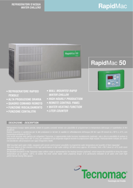
M
MA
AN
NU
UA
ALLEE U
UN
NIIC
CO
O •
• BOOKLET
IDROBLOC
®
IFI
E
A
IT
AERMEC S.P.A.
T
QU
L
RT
EM
E
D
C
ISO 9001 - Cert. nº 0128/3
Y SY
S
Sostituisce il:
Replace:
6379200_01 / 0310
IIDBUW
0406
6379200_02
INFORMAZIONI GENERALI • GENERAL INFORMATION
CARATTERISTICHE • FEATURES
Descrizione dell'unità • Unit description
Componenti principali • Main components
Descrizione dei componenti • Components description
Organi di sicurezza e regolazione • Safety and adjustment members
Accessori • Accessories
Imballo • Packing
L’alimentazione con acqua calda • The hot water feed
Criteri di scelta • Selection criteria
Considerazioni impiantistiche • Installation factors
Numero di terminali collegabili • Number of terminals that can be connected
Dati tecnici • Technical data
Potenza frigorifera totale ed assorbimento elettrico totale • Total chilling power and total electric absorption
Potenza termica ed assorbimento elettrico totale • Heating power and total electric absorption
Prevalenza utile nel funzionamento estivo • Effective head in summer operation
Perdite di carico interne nel funzionamento invernale • Internal load losses in winter operation
Fattore di correzione con acqua glicolata • Correction factors for glycol mix
Livelli di rumorosità • Sound data
Taratura organi di protezione • Safety devices settings
Campo di funzionamento • Working range
Schema di funzionamento • Diagram of operation
MISURE DI SICUREZZA • SAFETY MEASURES
Usi impropri • Improper uses
Anomalie di funzionamento • Operation problems
Simboli di sicurezza • Safety symbols
INSTALLAZIONE • INSTALLATION
Collegamenti idraulici • Hydraulic connections
Collegamenti elettrici • Electrical connections
FUNZIONAMENTO • OPERATION
Funzionamento dell'apparecchio • Device operation
Avviamento • Startup
Funzionamento invernale • Winter operation
Blocco della caldaia • Stopping of the boiler
Segnalazione di sovraccarico • Overload signalling
Prima della messa in funzione • Before starting-up
Messa in funzione dell'unità • Unit start-up
Protezione antigelo • Antifreeze protection
Caricamento e scaricamento dell’acqua • Loading and emptying the water
Descrizione del pannello comandi • Control panel description
Utilizzo del pannello comandi • Control panel use
Accensione e spegnimento • Switching on and off
Visualizzazione e impostazione dei paramentri di funzionamento
Viewing and setting the operating parameters
Taratura standard e campo di taratura dei dispositivi di regolazione
Standard calibration and calibration range of the adjustment devices
Segnalazioni • Items signalled
CARATTERISTICHE • FEATURES
Dati accessori • Accessories data
Dati dimensionali e posizione degli attacchi idraulici ed elettrici
Dimensions and position of the hydraulic and electric couplings
Spazi tecnici minimi • Minimum technical space
Sfiati e scarichi • Air vent and water discharge
Lay-out circuito frigorifero ed idraulico • Chiller and idraulic circuits legend
Schemi elettrici • Wiring diagrams
SERVIZIO ASSISTENZA TECNICA
4
6
7
8
9
10
11
12
13
14
15
16
17
18
19
20
21
22
23
24
25
27
28
29
31
33
34
35
37
43
3
OSSERVAZIONI • REMARKS
Questo manuale che descrive la macchina qui rappresentata. I capitoli descritti nella tabella sottoriportata, sono presenti in questo manuale.
Informazioni generali
Descrizione della macchina
versioni, accessori
Dati tecnici
Dati accessori
Misure di sicurezza
Usi impropri
Dati dimensionali
e posizioni attacchi
Precauzioni generali
Movimentazione
Installazione unità
Procedure per la messa
in funzione
Schemi elettrici
Uso
Manutenzione ordinaria
Individuazione guasti
Unico
x
x
x
x
x
x
x
x
x
x
x
x
x
x
x
This manual describe this machine. The chapters in the
table below are present in the manual.
General information
Machine description with
versions, accessories
Technical data
Accessory data
Safety measures
Improper use
Dimensions
and position of connections
General safety practices
Handling
Unit installation
Start-up procedures
Wiring diagrams
Use
Routine maintenance
Fault-finding
Booklet
x
x
x
x
x
x
x
x
x
x
x
x
x
x
x
Conservare i manuali in luogo asciutto, per evitare il deterioramento, per almeno 10 anni per eventuali riferimenti
futuri.
Store the manuals in a dry location to avoid deterioration, as
they must be kept for at least 10 years for any future reference.
Leggere attentamente e completamente tutte le informazioni contenute in questo manuale. Prestare particolarmente attenzione alle norme d’uso accompagnate dalle
scritte “PERICOLO” o “ATTENZIONE” in quanto, se non
osservate, possono causare danno alla macchina e/o a persone e cose.
All the information in this manual must be carefully read
and understood. Pay particular attention to the operating
standards with “DANGER” or “WARNING” signals as their
disrespect can cause damage to the machine and/or persons or objects.
ATTENZIONE: i collegamenti elettrici, l'installazione
dei ventilconvettori e dei loro accessori devono essere eseguiti solo da soggetti in possesso dei requisiti tecnico-professionali di abilitazione all'installazione, alla trasformazione, all'ampliamento e alla manutenzione degli impianti ed
in grado di verificare gli stessi ai fini della sicurezza e della
funzionalità (in questo manuale saranno indicati con il termine generico “personale provvisto di specifica competenza tecnica”).
In particolare per i collegamenti elettrici si richiedono le
verifiche relative a :
- Misura della resistenza di isolamento dell'impianto elettrico.
- Prova della continuità dei conduttori di protezione.
WARNING: check that the power supply is disconnected before performing operations on the unit.
WARNING: wiring connections installation of the fancoil
and relevant accessories should be performed by a technician who has the necessary technical and professional
expertise to install, modify, extend and maintain plants and
who is able to check the plants for the purposes of safety
and correct operation (In this manual authorised personnel
are referred to with the generic term "personnel with the
necessary technical skills").
In the specific case of electrical connections, the following
must be checked:
- Measurement of the isolation resistance on the electrical
system.
- Testing of the continuity of protection conductors.
Per anomalie non contemplate da questo manuale, interpellare tempestivamente il Servizio Assistenza di zona.
If any malfunctions are not included in this manual, contact
the local Aftersales Service immediately.
L'apparecchio deve essere installato in maniera tale da rendere possibili operazioni di manutenzione e/o riparazione.
La garanzia dell'apparecchio non copre in ogni caso i costi
dovuti ad autoscale, ponteggi o altri sistemi di elevazione
che si rendesero necessari per effettuare gli interventi in
garanzia.
The equipment should be installed so that maintenance
and/or repair services be possible.
The equipment warranty does not cover costs due to lifting
apparatus and platforms or other lifting systems required by
the warranty interventions.
AERMEC S.p.A. declina ogni responsabilità per qualsiasi
danno dovuto ad un uso improprio della macchina, ad una
lettura parziale o superficiale delle informazioni contenute
in questo manuale.
AERMEC S.p.A. declines all responsibility for any damage
whatsoever caused by improper use of the machine, and a
partial or superficial acquaintance with the information contained in this manual.
Il numero di pagine di questo manuale è: 44.
This manual has 44 pages.
4
AERMEC S.p.A.
IDROBLOC
®
I-37040 Bevilacqua (VR) Italia – Via Roma, 44
Tel. (+39) 0442 633111
Telefax 0442 93730 – (+39) 0442 93566
www .aermec. com - info @ aermec. com
DICHIARAZIONE DI CONFORMITÀ
DECLARATION OF CONFORMITY
Noi, firmatari della presente, dichiariamo sotto la nostra
esclusiva responsabilità, che la macchina in oggetto è
conforme a quanto prescritto dalle seguenti Direttive:
- Direttiva bassa tensione 73/23 CEE;
- Direttiva macchine 89/392 CEE e modifiche
91/368 CEE - 93/44 CEE - 93/68 CEE.
- Direttiva compatibilità elettromagnetica EMC89/336 CEE.
We declare under our own responsability that the above
equipment complies with provisions of the following
Standards:
- Low voltage Standard 73/23 EEC;
- Equipment Standard 89/392 EEC and amandments
91/368 EEC - 93/44 EEC - 93/68 EEC.
- Electromagnetic compatibility Standard EMC 89/336 EEC.
Bevilacqua, 1/6/2004
La Direzione Commerciale – Sales and Marketing Director
Luigi Zucchi
Aermec partecipa al Programma di
Certificazione EUROVENT. I prodotti interessati figurano nella Guida EUROVENT dei
Prodotti Certificati.
Aermec is partecipating in the EUROVENT
Certification Program. Products are as listed in
the EUROVENT Directory of Certified Products.
5
DESCRIZIONE DELL’UNITÀ • UNIT DESCRIPTION
IDROBLOC è un apparecchio adatto alla realizzazione di
impianti autonomi per il condizionamento estivo di piccolemedie utenze in edifici di carattere residenziale e commerciale.
IDROBLOC è concepito espressamente per l'accoppiamento
con fonte di acqua calda (caldaia di tipo murale, impianto di
riscaldamento centralizzato, teleriscaldamento ecc.) per ottenere, con un unico impianto di distribuzione e uniche unità
terminali del tipo a ventilconvettore, anche il riscaldamento
invernale. L’IDROBLOC può essere comunque impiegato
come un normale refrigeratore d’acqua. IDROBLOC è costituito da una unica unità da installare all’esterno sia a parete
che a pavimento, completa di tutti i componenti normalmente impiegati in impianti di questo tipo (pompa, vaso di espansione, accumulo inerziale, valvola di sicurezza, rubinetto di
scarico impianto, filtro meccanico, flussostato). L’apparecchio può essere collegato alla caldaia in modo da poter gestire il cambio di stagione estivo/invernale con un solo pulsante; su IDROBLOC sono disponibili due coppie di morsetti
con i quali si può togliere il consenso alla caldaia quando
IDROBLOC è acceso, comandare valvole On/Off per la suddivisione in zone dell’impianto o per intercettare il circuito
caldo a monte di IDROBLOC quando questo è acceso.
Il sistema è controllato da un microprocessore.
IDROBLOC è un gruppo refrigeratore d'acqua di limitato
assorbimento elettrico, che può alimentare con acqua fredda
un numero relativamente grande di unità terminali, consentendo all'utente di condizionare contemporaneamente un
certo numero di locali, a suo gradimento, con la sola limitazione della potenza frigorifera a disposizione.
Deve necessariamente essere installato all'esterno.
IDROBLOC is a device suitable for producing autonomous,
summertime air conditioning plants for small/medium-size
users in residential and commercial buildings.
IDROBLOC is purpose built for connection with a hot water
source (built-in boiler, central heating installation, remote
heating, etc.) to provide heating in the wintertime with a
single distribution plant and unique fan coil type terminal
units. The IDROBLOC can nonetheless be used as a normal
water cooler. IDROBLOC is made of a single unit to be
installed externally, either on the wall or on the floor, complete with all the components generally used in plants of this
type (pump, expansion tank, inertia storage, safety valve,
plant discharge cock, mechanical filter, flow switch). The
device can be connected to the boiler so as to manage the
change of season, winter/summer, with a single button; two
pairs of terminals are provided on IDROBLOC with which to
remove boiler enablement when IDROBLOC is on, and to
control On/Off valves for the subdivision of the plant into
zones or to intercept the hot circuit upstream of the IDROBLOC when it is on.
The system is controlled by a microprocessor.
IDROBLOC is a water chiller unit of with limited electric
absorption, which can feed with cold water a relatively large
number of terminal units, allowing the user to simultaneously condition a certain number of rooms, at his discretion,
with a simple restriction on the cooling power available.
It must necessarily be installed outside.
COMPONENTI PRINCIPALI • MAIN COMPONENTS
1 Pompa acqua • Water pump
2 Valvola sfiato aria • Air bleeder valve
3 Valvola a due vie • Two-way valve
4 Scambiatore a piastre • Exchanger made of plates
5 Pannello comandi • Commands panel
6 Serbatoio di accumulo • Storage tank
7 Vaso d'espansione • Expansion tank
8 Flussostato • Flow switch
9 Compressore • Compressor
10 Quadro elettrico • Electric panel
11 Valvola sfiato aria • Air bleeder valve
10
12 Attacchi idraulici • Hydraulic couplings
13 Scambiatore lato aria • Air-side exchanger
14 Griglia di protezione • Protection grille
15 Gruppo ventilante • Fan assembly
16 Rubinetto di svuotamento • Emptying cock
17 Resistenza antigelo • Anti-frost electric heater
18 Staffe per installazione a pavimento (rimovibili)
Brackets for floor-standing installation (removable)
19 Filtro meccanico • Mechanical filter
20 Valvola unidirezionale • Unidirectional valve
11
10
5
11
7
5
19
19
14
20
20
9
7
15
13
9
15
14
1
1
8
2
8
2
6
13
3
12
3
6
12
17
17
16
16
18
6
4
4
Fig. 1
18
Fig. 2
DESCRIZIONE DEI COMPONENTI • COMPONENTS DESCRIPTION
TELAIO E PANNELLI DI COPERTURA
Realizzato in lamiera di acciaio zincato verniciata a caldo con
polveri poliuretaniche dopo trattamento di passivazione, è in
grado di resistere a lungo all’azione degli agenti atmosferici.
GRUPPO VENTILANTE
Costituito da un ventilatore elicoidale azionato direttamente
dal motore elettrico asincrono monofase con protezione termica interna.
È provvisto di griglia di protezione secondo norme CEI EN
60335-2-40.
CIRCUITO FRIGORIFERO
Realizzato in tubo di rame ricotto, saldato con lega d'argento.
Le unità IDROBLOC 3 - 3H sono provviste di un capillare per
la laminazione mentre le unità IDROBLOC 5 - 5H sono dotate di una valvola termostatica.
COMPRESSORE
Il compressore ermetico ad alta efficenza, isolato acusticamente è azionato da un motore elettrico con protezione
termo-amperometrica ed è montato su supporti elastici antivibranti.
Le unità IDROBLOC 3 - 3H sono provviste di compressore
rotativo mentre le unità IDROBLOC 5 - 5H sono dotate di
compressore Scroll.
SCAMBIATORE LATO ARIA
La batteria di scambio termico è realizzata in tubo di rame
rigato internamente ed alette in alluminio di tipo corrugato.
SCAMBIATORE LATO ACQUA
Lo scambiatore di calore R407C-acqua, di tipo a piastre, in
acciaio inossidabile AISI 316, estremamente compatto, è
dimensionato per sopportare una portata d’acqua con differenza di temperatura tra ingresso e uscita fino a 2 °C; lo
scambiatore è all’interno dell’accumulo.
SERBATOIO D’ACCUMULO ACQUA
Serve per diminuire il numero di spunti del compressore ed
uniformare la temperatura dell’acqua da inviare alle utenze.
RESISTENZA ELETTRICA ANTIGELO
Resistenza elettrica per l’accumulo. Evita il congelamento
dell’acqua contenuta nell’accumulo durante le soste invernali. Quando il microprocessore attiva la protezione antigelo ferma il compressore ed il ventilatore.
La protezione antigelo è attiva solo se Idrobloc è alimentato con corrente elettrica anche nei periodi freddi.
POMPA
Consente di far circolare l’acqua nel circuito utenze.
VASO D’ESPANSIONE
Del tipo chiuso a membrana, consente la dilatazione
dell’acqua nell’impianto.
VALVOLA A DUE VIE
La valvola a due vie impedisce il flusso dell’acqua verso la
caldaia quando il compressore è attivo nel funzionamento
in raffreddamento.
VALVOLA INVERSIONE CICLO
Solo per la versione a pompa di calore.
La valvola a inversione inverte il flusso di refrigerante al
variare del funzionamento Raffeddamento/Pompa di calore.
COLLEGAMENTI IDRAULICI
Tutte le parti e i collegamenti idraulici interni interessati da
acqua a bassa temperatura sono adeguatamente coibentati.
Nella parte inferiore del modulo sono posizionati gli attacchi
idraulici per il collegamento alla caldaia (o all'eventuale circuito di distribuzione dell'acqua calda) e al circuito utenze.
QUADRO ELETTRICO
Contiene l’interruttore di accensione e spegnimento, la
sezione di potenza e la gestione dei controlli e delle sicurezze con microprocessore secondo norme CEI EN 603352-40, è protetta verso l’esterno da uno sportellino apribile
con grado di protezione IP54.
CHASSIS AND COVER PANELS
Made of zinc-plated steel sheet, hot-painted with polyurethane
powders after passivating treatment, it can resist the action of
atmospheric agents for long periods.
FAN ASSEMBLY
Consisting of a helical fan unit, driven directly by the asynchronous, single-phase electric motor with internal thermal
protection.
It is provided with a protection grille as required by the CEI
EN 60335-2-40 standards.
COOLING CIRCUIT
Made of an annealed copper tube, welded with silver alloy.
IDROBLOC 3 - 3H units are equipped with a capillary tube.
IDROBLOC 5 - 5H units are equipped with a thermostatic
valve.
COMPRESSOR
The high-efficiency, hermetically sealed and acoustically
insulated compressor, is driven by an electric motor with
thermal-ammeter type protection and is mounted on vibration damping elastic supports.
IDROBLOC 3 - 3H units are equipped with rotary compressor.
IDROBLOC 5 - 5H units are equipped with Scroll compressor.
AIR-SIDE EXCHANGER
The heat exchange coil is made of internally grooved copper
tube and corrugated aluminium type fins.
WATER-SIDE EXCHANGER
The extremely compact, R407C-water, plate-type, heat
exchanger in AISI 316 stainless steel, is sized for a water
flow with temperature difference between input and output
of up to 2 °C; the exchanger is inside the storage tank.
WATER ACCUMULATION TANK
Used to reduce the number of start-ups of the compressor
and render the temperature of the water to be sent to the
consumers uniform.
ANTIFREEZE ELECTRIC HEATER
Electric heater for the storage. Avoids the water contained in
the storage freezing over during the winter stops. When the
microprocessor activates the antifreeze protection, it stops
the compressor and the fan unit.
The antifreeze protection is only active if the Idrobloc is
fed with electric current even in the cold periods.
PUMP
Allows water to be circulated in the user circuit.
EXPANSION TANK
Of the closed type, with a membrane, allows expansion of
the water in the plant.
TWO-WAY VALVE
The two-way valve prevents the water from flowing towards
the boiler when the compressor is active in cooling operation.
CYCLE INVERSION VALVE
Only for the heat pump version.
The cycle inversion valve inverts the flow of coolant when
there is a Cooling/Heat Pump operation switch.
HYDRAULIC CONNECTIONS
All the internal hydraulic parts and connections concerned
by low temperature water flow are suitably insulated.
Found in the module lower part are the hydraulic connections for the connection to the boiler (or to the hot water
distribution circuit, where applicable) and to the user circuit.
ELECTRIC PANEL
Contains the on / off switch, the power section and the
management of the checks and the safeties with microprocessor according the CEI EN 60335-2-40 standards, and is
protected from the external by a open/shut door with protection degree IP54.
7
ORGANI DI REGOLAZIONE E SICUREZZA • CONTROL AND SAFETY DEVICES
SCHEDA A MICROPROCESSORE
Composta da scheda di gestione, controllo e visualizzazione.
Funzioni svolte:
• regolazione temperatura acqua ingresso evaporatore.
• ritardo avviamento compressore.
• funzionamento estivo o invernale in pompa di calore
con gestione sbrinamento.
• gestione dispositivo bassa temperatura (accessorio).
• conteggio ore funzionamento compressore.
• conteggio ore funzionamento pompa.
• start/stop.
• reset.
• autostart dopo caduta di tensione.
• funzionamento con possibilità di controllo remoto.
• visualizzazione stato macchina:
ON/OFF compressore;
funzionamento estivo;
funzionamento invernale.
• gestione allarmi:
flussostato.
bassa pressione;
alta pressione (IDROBLOC 5-5H);
antigelo;
sovraccarico compressore.
• visualizzazione dei seguenti parametri:
temperatura ingresso acqua;
temperatura uscita acqua;
temperatura sonda batteria (se presente);
• visualizzazione allarmi.
• impostazioni set:
set caldo;
set freddo;
differenziale freddo;
differenziale caldo.
Ai morsetti 5 - 5A è possibile collegare una segnalazione
esterna di Allarme. Il contatto, normalmente aperto, è privo
di tensione e può comandare un carico da 250 V - 1A.
Di seguito sono descritte in dettaglio le principali funzioni
gestite dalla scheda a microprocessore.
MICROPROCESSOR CARD
Composed of a management, control and display card.
The microprocessor card has the following functions:
• regulation of the evaporator inlet water.
• compressor timing delay.
• summer operation or winter operation as a heat pump
with defrost management.
• management of low temperature control (accessory).
• compressor working hourmeter.
• pump working hourmeter.
• start/stop.
• reset.
• autostart after power failure.
• operation with possibility of remote control.
• machine status display:
compressor ON/OFF;
summer operation;
winter operation.
• alarm management:
fluxostat;
low pressure;
high pressure (IDROBLOC 5-5H);
antifreeze;
compressor overload.
• display of the following parameters:
water inlet temperature;
water outlet temperature;
heat exchanger sensor temperature;
• alarm display.
• set point adjustment:
heating set point;
cooling set point;
cooling differential;
heating differential.
An external Alarm report line may be connected to the 5 - 5A
terminals. The normally open contact is at zero potential and
can control a load of 250 V - 1A.
Described below in detail are the main functions managed
by the microprocessor board.
– TASTO DI ACCENSIONE E SPEGNIMENTO
Il tasto è inserito all’interno del pannello comandi ed è protetto dalle intemperie e da manomissioni accidentali con un
coperchio traparente che consente anche di verificare lo stato.
Con il tasto in posizione di spento e l’unità in tensione è
attiva la protezione antigelo.
– ON / OFF KEY
The key is inserted on the inside of the commands panel and is
protected against poor weather and accidental contacts by a
transparent cover which also allows its status to be checked.
With the key in the Off position, and the unit under live voltage, the antifreeze protection is active.
– TERMOSTATO DI LAVORO
Il grafico riportato in fig. 11 illustra come viene calcolato il
gradino d’intervento della macchina a seconda dei set di
funzionamento impostati.
– WORK THERMOSTAT
The graph shown in fig. 11 illustrates how the machine's
intervention step is calculated, depending on the operating
sets selected.
– GESTIONE COMPRESSORE (CP)
Il microprocessore attiva il compressore in base alla temperatura d’ingresso dell’acqua, controllando anche il numero
massimo di accensioni orarie.
– COMPRESSOR CONTROL(CP)
The microprocessor activates the compressor depending on
the water input temperature, also checking the maximum
number of switchings-on per hour.
– GESTIONE DELLA POMPA DELL’ACQUA SULL’EVAPORATORE
La pompa dell’acqua sul lato evaporatore viene messa in
funzione per prima in fase di avviamento, dopo 150 secondi parte il compressore.
Dopo l’avviamento questa pompa rimane sempre in funzione.
Allo spegnimento dell’unità rimane in funzione per 1 minuto.
– CONTROL OF THE WATER PUMP ON THE EVAPORATOR
The water pump on the evaporator side is started up first in
the start-up phase, after 150 seconds the compressor starts.
After start-up, this pump remains in operation all the time.
When switched off, the unit remains in operation for 1
minute.
– AUTOSTART CON “START MEMORY”
L’unità, al ritorno della tensione, si porrà nello stesso stato
precedente al black-out. Se la macchina era in funzione
riprenderà il suo funzionamento, se invece era spenta
rimarrà spenta.
– AUTOSTART WITH "START MEMORY"
The unit, when the voltage returns, will go back into in the
same conditions as before the black-out. If the machine was
in operation, it will resume operation, if, on the other hand,
it was off, it will stay off.
– VALVOLA DI SICUREZZA CIRCUITO IDRAULICO
Tarata a 3 bar , protegge il circuito idraulico dal possibile
funzionamento con pressioni eccessive lato acqua.
– HYDRAULIC CIRCUIT SAFETY VALVE
Calibrated for 3 bar, it protects the hydraulic circuit from
possible operation with excessive pressures on the water-
8
– TERMOSTATO ANTIGELO
Protegge lo scambiatore e i componenti interni dell’IDROBLOC
dal pericolo di gelo attivando la resistenza elettrica antigelo.
La protezione antigelo è attiva solo se IDROBLOC è alimentato con corrente elettrica anche nei periodi freddi.
– PRESSOSTATO DI BASSA PRESSIONE
A taratura fissa, posto sul lato a bassa pressione del circuito
frigorifero, arresta il funzionamento del compressore in caso
di pressioni anomale di lavoro.
– PRESSOSTATO DI ALTA PRESSIONE (IDROBLOC 5-5H)
A taratura fissa, posto sul lato a alta pressione del circuito
frigorifero, arresta il funzionamento del compressore in caso
di pressioni anomale di lavoro.
– FLUSSOSTATO
Il fussostato è montato all’entrata dello scambiatore e, in
caso di portata d’acqua troppo bassa, ferma il compressore,
il ventilatore e la pompa.
side.
– ANTIFREEZE THERMOSTAT
Protects the exchanger and the internal components of the
IDROBLOC from the frost hazard by activating the antifreeze
electric heater.
The antifreeze protection is only active if the Idrobloc is fed
with electric current even in the cold periods.
– LOW PRESSURE PRESSURE SWITCH
Of fixed calibration, located on the low pressure side of the
cooling circuit, stops the compressor operation in case of
anomalous work pressures.
– HIGH PRESSURE SWITCH (IDROBLOC 5-5H)
Of fixed calibration, located on the high pressure side of the
cooling circuit, the switch shuts compressor operation in the
event of abnormal operating pressure levels
– FLOW SWITCH
The flow switch is fitted on the exchanger input and, if the
water flow is too low, stops the compressor, the fan unit and
the pump.
ACCESSORI • ACCESSORIES
DCPX42 – DISPOSITIVO PER BASSE TEMPERATURE
Solo per la versione solo freddo.
Consente un corretto funzionamento, in raffreddamento,
con temperature esterne inferiori a 20 °C e fino a – 10 °C.
È costituito da un trasduttore montato sul lato di alta pressione e da un regolatore del numero di giri del ventilatore
dell’unità.
PRD – PANNELLO REMOTO INTELLIGENTE
Replica a distanza le funzionalità del pannello comandi a
bordo macchina. La distanza massima d’installazione consentita è di 150 m con cavo a 6 poli più schermatura di
sezione minima di 0,5 mm2.
PR1 – PANNELLO REMOTO SEMPLIFICATO
Consente di eseguire i controlli base della mcchina (accensione / spegnimento, cambio modalità di funzionamento,
segnalazione allarmi). La distanza massima d’installazione
consentita è di 30 m con cavo con schermatura di sezione
minima di 0,5mm2, a 4 poli per la versione solo freddo o a
6 poli per la versione a pompa di calore.
DCPX42 - DEVICE FOR LOW TEMPERATURES
For the cold only version.
Allows proper operation, in cooling, with external temperatures lower than 20 °C and as low as - 10 °C.
Comprises a transducer fitted on the high pressure side and
a regulator of the number of fan unit revolutions.
PRD - INTELLIGENT REMOTE PANEL
Remote relays the functions of the commands panel on
board the machine. The maximum installation distance
allowed is 150 m with 6-pole cable plus shielding, minimum
cross-section area 0.5 mm2.
PR1 - SIMPLIFIED REMOTE PANEL
May be used to implement the machine basic controls (switch-on/switch-off, operation mode change, alarm signalling).
The maximum installation distance allowed is of 30 m with
cable with shielding of minimum cross section area 0.5mm2,
4-poles for the cold only version or 6-poles for the heat
pump version.
SDP – SCHEDA PER REMOTAZIONE
Necessaria per poter installare l’accessorio PR1 fino a 150 m.
SDP - REMOTE RELAYING BOARD
Needed to be able to install the accessory PR1 up to 150 m
away.
VT7 – SUPPORTI ANTIVIBRANTI
Gruppo di quattro antivibranti da montare sotto il basamento in lamiera, nei punti già predisposti. Servono ad attenuare le vibrazioni prodotte dal compressore durante il suo
funzionamento.
VT7 - VIBRATION DAMPING SUPPORTS
Group of four vibration dampers to be mounted under the
base plate, in the points already prepared. Used to attenuate the vibrations produced by the compressor when in operation.
TABELLA DI COMPATIBILITÀ DEGLI ACCESSORI • ACCESSORIES COMPATIBILITY TABLE
Mod. IBROBLOC
DCPX 42
PRD
PR1
VT 7
3
✔
✔
✔
✔
3H
✔
✔
✔
5
✔
✔
✔
✔
5H
✔
✔
✔
9
IMBALLO • PACKING
Le unità vengono spedite con imballo standard costituito da
una scatola di cartone con protezioni in polistirolo espanso. Per particolari esigenze, su richiesta, l'imballo standard
può essere completato con una gabbia di legno.
The units are shipped with standard packing consisting of a
cardboard box with polystyrene foam protection. For special
requirements, on request, a wooden crate may supplement
the standard packing.
L’ALIMENTAZIONE CON ACQUA CALDA • THE HOT WATER FEED
IDROBLOC può essere alimentato con una portata di acqua
calda di qualsiasi provenienza che viene poi distribuita ai
ventilconvettori; in ogni caso, per garantire un buon funzionamento del sistema è opportuno controllare le caratteristiche della pompa di circolazione dell’acqua calda, che deve
assicurare la giusta portata d’acqua alle singole utenze.
Infatti, l’acqua calda, prima di essere distribuita alle utenze,
entra in IDROBLOC, dove incontra una resistenza proporzionale alla portata secondo quanto illustrato nella tav. 6.
IDROBLOC can be fed with a flow of hot water of various
origin which can then distributed to the fan coils; in any
case, to ensure proper system operation, it is a good idea to
check the characteristics of the hot water pump, which
must ensure the right flow of water to the individual users.
In fact, the hot water, before being distributed to the users,
enters the IDROBLOC, where it encounters a resistance proportional to the flow as illustrated in figure. 6.
CRITERI DI SCELTA • SELECTION CRITERIA
Le curve di tav. 2 riportano i coefficienti moltiplicativi per ottenere, a partire dai valori nominali, la resa frigorifera e la potenza elettrica assorbita totale al variare della temperatura dell’aria
esterna e della temperatura dell’acqua prodotta. I valori indicati da tali diagrammi sono riferiti ad un salto termico costante
sull’acqua, di 5 °C. Per salti termici diversi, moltiplicare la resa
frigorifera per i valori della tabella riportata di seguito.
Salto termico acqua refrigerata
2°C
3°C
4°C
5°C
7°C
9°C
Fattore correttivo Pot. frigorifera
0,97
0,98
0,99
1,00
1,02
1,04
The curves of figure 2 give the multiplication coefficients with
which to obtain, starting from the nominal values, the chilling
efficiency and the total electric power absorbed upon variation
of the external air temperature and the temperature of the
water produced. The values indicated by these diagrams are
with reference to a constant thermal excursion of the water, of
5 °C. For different thermal excursions, multiply the chilling effiChilled water thermal excursion
2°C
3°C
4°C
5°C
7°C
9°C
Cooling power correction factor
0,97
0,98
0,99
1,00
1,02
1,04
La potenza assorbita non è influenzata apprezzabilmente
dal salto termico dell’acqua.
La curva di tav. 5 forniscono le prevalenze utili a disposizione per l’impianto di distribuzione dell’acqua refrigerata.
La tav. 6 fornisce le perdite di carico interne di IDROBLOC
alle varie portate per l’acqua proveniente dalla caldaia.
Conoscendo la caratteristica del circolatore dell’eventuale
caldaia o, in ogni caso, la prevalenza a disposizione a
monte di IDROBLOC, si può così risalire alla prevalenza
utile disponibile per l’impianto di distribuzione.
ciency by the values shown in the following table.
The power absorbed is not significantly affected by the thermal
excursion of the water.
The curve of figure 5 give the effective heads available for the
chilled water distribution plant.
Fig. 6 shows the load losses inside the IDROBLOC at the
various flows for the water coming from the boiler. Knowing
the characteristic of the circulation system in any boiler present
or, in any case, the head available upstream of IDROBLOC, we
can calculate the useful head available for the distribution
plant.
CONSIDERAZIONI IMPIANTISTICHE • INSTALLATION FACTORS
Caratteristica peculiare del modulo IDROBLOC è di poter alimentare, con una portata d’acqua a temperatura prefissata,
un numero di ventilconvettori la cui resa frigorifera totale
sarebbe superiore alla potenza frigorifera erogata dal modulo.
Si può così realizzare un impianto che distribuisca acqua
refrigerata ad un numero relativamente grande di ventilconvettori, sempre pronti ad entrare in funzione. Naturalmente
il numero di essi che possono funzionare contemporaneamente è limitato dalla potenza frigorifera a disposizione.
Sarà l’utente ad escludere i ventilconvettori che riterrà
opportuno, in funzione dell’occupazione dei locali. Per
assicurare la massima indipendenza tra i vari locali, si consiglia l’installazione di ventilconvettori dotati di termostato
ambiente incorporato.
L’esclusione dal funzionamento estivo di alcuni ventilconvettori non avviene intercettando idraulicamente le singole
unità, ma semplicemente tenendole spente. In queste ultime, l’acqua refrigerata circola con un incremento di temperatura minimo.
Nella tubazione di ritorno dell’impianto si realizza allora la
miscela di acqua a diverse temperature: più calda la portata
10
A particular feature of the IDROBLOC module is that it can
supply, with a flow of water at a preestablished temperature, a number of fan coils whose total chilling efficiency
would be greater than the cooling power delivered by the
module.
A plant that can distribute chilled water to a relatively large
number of fan coils, always ready to enter into operation,
can be produced in this way. Naturally the number of these
that can operate simultaneously is limited by the cooling
power available. It will be the user to exclude all fan coils he
considers suitable, depending on the number of persons in
the room. To ensure the maximum independence between
the various rooms, it is recommended that fan coils with
incorporated environment thermostat be installed.
Exclusion from summertime operation of some fan coils is
not effected by hydraulically intercepting the single units,
but simply by keeping them switched off. In the latter, the
chilled water circulates with a higher minimum temperature.
In the return piping of the plant, in this case a mix is produced of water at different temperatures: a hotter flow coming
from the fan coils in operation and practically at the produc-
proveniente dai ventilconvettori in funzione e praticamente
alla temperatura di produzione quella proveniente dai ventilconvettori spenti. La temperatura dell’acqua all’ingresso
dell’evaporatore è allora una media pesata delle varie temperature di ritorno.
Ciò è consentito dal fatto che l'evaporatore a piastre del
modulo IDROBLOC può essere attraversato da una portata
molto superiore a quella di un normale refrigeratore, a
parità di potenza erogata. Grazie anche alle caratteristiche
della pompa incorporata, la portata d'acqua può essere tale
da assicurare un salto termico sull'evaporatore di 2 °C.
Nel caso fosse in funzione un numero eccessivo di ventilconvettori, la potenza frigorifera assorbita da questi sarebbe
maggiore della potenza messa a disposizione dal modulo
IDROBLOC, e pertanto si potrebbe incorrere nella situazione di non raggiungere adeguate condizioni di benessere
negli ambienti serviti. Questa condizione di lavoro, peraltro
non pericolosa per il buon funzionamento dell’apparecchio,
viene segnalata sul pannello di controllo tramite la comparsa della scritta “ Ht ” (solo sulla versione “solo freddo).
L’eventuale impossibilità di poter utilizzare contemporaneamente tutti i ventilconvettori installati in generale non costituisce una limitazione in quanto l’esigenza del condizionamento sopravviene in locali diversi ed in periodi diversi: per
esempio in una abitazione civile possono essere individuate
una zona giorno ed una zona notte da servire alternativamente.
Nel funzionamento in pompa di calore IDROBLOC consente
di disporre di una portata d’acqua calda utilizzabile per il
riscaldamento degli ambienti. Questa possibilità permette di
riscaldare gli ambienti nelle stagioni primaverile ed autunnale
senza dover ricorrere all’accensione della caldaia.
Analogamente a quanto succede per il funzionamento in raffreddamento il numero di ventilconvettori che può entrare
contemporaneamente in funzione dipende dalla potenza termica erogata dalla macchina.
Nel funzionamento invernale, la potenzialità termica di
riscaldamento deve ovviamente essere sufficiente al funzionamento contemporaneo di tutte le unità terminali installate.
Se si utilizza il modulo IDROBLOC come un refrigeratore
tradizionale, il numero di ventilconvettori collegabili dipende dalla potenza frigorifera che si ha a disposizione; in questo caso, tutte le unità installate possono funzionare contemporaneamente.
Attenzione: la protezione antigelo è attivata solo quando
l’unità è alimentata, si consiglia pertanto di lasciare IDROBLOC alimentato elettricamente anche nella stagione fredda.
tion temperature that coming from the fan coils that are off.
The temperature of the water at the evaporator input is in
this case the weighted average of the various return temperatures.
This is permitted by the fact that the plates type evaporator
of the IDROBLOC module can be traversed by a flow much
greater than that of a normal cooler, for like delivered power
values. Thanks also to the incorporated pump's characteristics, the flow of water may be such as to ensure a thermal
excursion on the evaporator of 2 °C.
Where an excessive number of fan coils is in operation, the
cooling power absorbed by these would be greater than the
power made available by the IDROBLOC module, and
there could therefore be a situation in which the desired
well-being conditions in the environments served are not
attained. This work condition, which is not in any way dangerous for proper device operation, is signalled on the control panel through the appearance of the marking " Ht "
(only on the "cold only" version).
The impossibility of using all the installed fan coils simultaneously does not in general constitute a limitation as the
conditioning requirement is in different rooms and at different times: for example in a residential dwelling, a day zone
and a night zone may be identified, to be serviced alternatively.
In heat pump operation, IDROBLOC can lay on a flow of
hot water that may be used to heat rooms with. This possibility means that rooms can be heated in the spring and
autumn seasons without having to switch on the boiler. In
the same way as in cooling operation, the number of fan
coils that can come into operation simultaneously depends
on the thermal power delivered by the machine.
In winter operation, the thermal heating capacity must
obviously be sufficient for simultaneous operation of all the
terminal units installed.
If using the IDROBLOC module as a traditional chiller, the
number of fan coils that can be connected depends on the
cooling power that is available; in this case, all the units
installed can operate simultaneously.
Warning: the antifreeze protection is activated only when
the unit is powered, it is therefore recommended to leave
the IDROBLOC under electric power even in the cold season.
NUMERO DI TERMINALI COLLEGABILI • NUMBER OF TERMINALS THAT CAN BE CONNECTED
Il numero di ventilconvettori collegabili in parallelo è legato
alle caratteristiche del circolatore della caldaia e di IDROBLOC: la portata di acqua in circolazione, dipendente dalle
perdite del circuito idraulico, deve essere tale da alimentare
in modo soddisfacente ogni ventilconvettore: in qualsiasi
condizione di esercizio, all’interno di ogni ventilconvettore
deve circolare una quantità minima di acqua.
La determinazione del numero di ventilconvettori collegabili
è quindi legata alla portata totale di acqua in gioco, la quale
è la somma di quelle necessarie ai singoli ventilconvettori
per soddisfare il carico termico relativo a ciascuno di essi.
The number of fan coils that can be connected in parallel is
linked to the characteristics of the boiler circulation system
and of the IDROBLOC: the flow of water in circulation,
depending on the losses in the hydraulic circuit, must be
sufficient to feed each fan coil in a satisfactory way: in any
operating condition, a minimal quantity of water must be
circulating inside each fan coil.
Determining the number of fan coils that can be connected
is therefore in relation to the total flow of water in backlash,
which is the sum of those needed by the single fan coils to
satisfy the thermal load relative to each of these.
11
TAV. 1 DATI TECNICI • TECHNICAL DATA
Compressore • Compressor
Gas frigorifero • Refrigerant gas
Contenuto acqua scambiatore • Heat exchanger water content
Pressione sonora • Sound pressure
Potenza sonora • Sound power
Portata aria • Air flow
n° giri ventilatore • Fan speed
Velocità pompa • Pump speeds
Volume serbatoio accumulo • Storage tank capacity
Capacità vaso d’espansione •
Pressione di precarica •
Taratura valvola di sicurezza •
Attacchi idraulici e dimensioni • Water connectinos and dimensions
Attacchi idraulici impianto (Ø femmina)
Water connections impianto (Ø female)
Attacchi idraulici caldaia (Ø femmina)
Water connections caldaia (Ø female)
Altezza • Height
Dimensioni • Dimensions
Larghezza • Width
Profondità • Depth
Peso a vuoto • Net weight
Le prestazioni sono riferite alle seguenti condizioni:
Tensione di alimentazione: 230 V / 1 / 50 Hz (±10%).
* = Inclusa la pompa di circolazione e senza resistenza antigelo.
Pressione sonora misurata in campo libero con una distanza
frontale di 10 m e fattore di direzionalità = 2.
❆ Raffreddamento: temperatura acqua uscente 7 °C; ∆t = 5 °C
temp. aria esterna 35 °C B.S.
❊ Riscaldamento: temperatura acqua uscente 50 °C; ∆t = 5 °C
temp aria esterna 7 °C B.S., 6 °C B.U.
12
3
3H
5
5H
[W]
[W/W]
[W]
[A]
[l/h]
[l/h]
[kPa]
3500
2,33
1500
7,30
600
2000
69
3200
2,13
1500
7,30
550
2000
69
6700
2,39
2800
13,20
1150
2000
58
6700
2,31
2900
13,80
1150
2000
58
[W]
[W/W]
[W]
[A]
[l/h]
[l/h]
[kPa]
-
3850
2,66
1450
7,20
660
2000
67
-
7800
2,52
3100
14,70
1340
2000
56
[W]
145
145
180
180
[A]
0,64
0,64
0,80
0,80
[A]
[W]
[A]
[A]
33,50
200
10
2
33,50
200
10
2
75
200
20
2
75
200
20
2
Scroll
1
R407C
0,75
39
67
2300
825
3
25
2
1,50
3
Scroll
1
R407C
0,75
39
67
2300
825
3
25
2
1,50
3
IDROBLOC
Raffreddamento • Cooling
❆ Potenzialità frigorifera • Cooling capacity
❆ E.E.R.
❆ Potenza assorbita totale* • Total input power*
❆ Corrente assorbita totale* • Total input current*
nominale • nominal
❆ Portata acqua • Water flow
massima • max.
❆ Prevalenza utile a portata nominale • Effective pressure nominal flow
Riscaldamento • Heating
❊ Potenzialità termica • Heating capacity
❊ C.O.P.
❊ Potenza assorbita totale* • Total input power*
❊ Corrente assorbita totale* • Total input current*
nominale • nominal
❊ Portata acqua • Water flow
massima • max.
❊ Prevalenza utile a portata nominale • Effective pressure nominal flow
Dati elettrici • Electrical data
Potenza assorbita dalla pompa di circolazione (massima velocità)
Power absorbed by the circulation pump (maximum speed)
Corrente assorbita dalla pompa di circolazione (massima velocità)
Current absorbed by the circulation pump (maximum speed)
Corrente di spunto • Peak current
Resistenza antigelo • Defrost heater
Fusibile compressore • Compressor fuse
Fusibile circuito ausiliario • Circuito ausiliario fuse
Dati tecnici generali • Main technical data
tipo / type Rotativo • Rotary
n°
1
1
R407C
R407C
[dm3]
0,75
0,75
dB (A) 33,5
33,5
dB (A) 61,5
61,5
[m3/h] 1200
1200
[g/min - rpm] 680
680
n°
3
3
[l]
25
25
[l]
1
1
[bar]
1,50
1,50
[bar]
3
3
“Gas
3/4” F
3/4” F
3/4” F
3/4” F
“Gas
1/2” F
1/2” F
1/2” F
1/2” F
[mm]
[mm]
[mm]
[kg]
990
450
450
79
990
450
450
80
1063
606
563
116
1063
606
563
119
Performances refer to following conditions:
Power supply: 230 V / 1 / 50 Hz (±10%).
* = Including the circulation pump and without anti-frost electric heater.
Sound pressure measured at 10 mt.s in free field
conditions Q = 2.
❆ Cooling: temperature of processed water 7 °C; ∆t = 5 °C
ambient air temperature 35 °C D.B.
❊ Heating: temperature of processed water 50 °C; ∆t = 5 °C
ambient air temperature 7 °C D.B., 6 °C W.B.
TAV 2
POTENZA FRIGORIFERA TOTALE ED ASSORBIMENTO ELETTRICO TOTALE
COOLING CAPACITY AND TOTAL INPUT POWER
La potenza frigorifera resa e la potenza elettrica assorbita in
condizioni diverse da quelle nominali si ottengono moltiplicando i valori nominali (Pf, Pa) per i rispettivi coefficienti
correttivi (Cf, Ca).
Il diagramma seguente consente di ricavare i coefficienti correttivi da utilizzare per i refrigeratori nel funzionamento a
freddo; in corrispondenza di ciascuna curva è riportata la
temperatura dell’aria esterna alla quale si riferisce.
The yielded cooling capacity and electrical input power in
conditions other than nominal conditions are obtained by
multiplying the nominal values (Pf, Pa) by the respective
corrective coefficients (Cf, Ca).
The diagram below gives the correction factors to be
applied to chillers during cooling. For each curve, the diagram shows the external air temperature to which it refers.
POTENZA FRIGORIFERA TOTALE • COOLING CAPACITY
1,4
Te 20°C
1,3
Te 25°C
Te 30°C
1,2
Te 35°C
1,1
Te 40°C
temperatura aria esterna [°C]
ambient temperature [°C]
Coefficente correttivo della potenza frigorifera (Pf)
Corrective coefficient for cooling capacity (Pf)
1,5
1
0,9
0,8
5
6
7
8
9
10
11
12 Tuw [°C]
Temperatura uscita acqua [°C] • Water outlet temperature [°C]
ASSORBIMENTO ELETTRICO TOTALE • TOTAL INPUT POWER
Te 40°C
1,1
Te 35°C
1
Te 30°C
Te 25°C
0,9
Te 20°C
temperatura aria esterna [°C]
ambient temperature [°C]
Coefficente correttivo della potenza assorbita totale (Pa)
Corrective coefficient for total input power (Pa)
1,2
0,8
0,7
0,6
5
6
7
8
9
10
11
12 Tuw [°C]
Temperatura uscita acqua [°C] • Water outlet temperature [°C]
13
TAV 3
POMPE DI CALORE: POTENZA TERMICA POTENZA ASSORBITA
HEAT PUMPS: HEATING CAPACITY AND TOTAL INPUT POWER
La potenza termica resa e la potenza elettrica assorbita in
condizioni diverse da quelle nominali si ottengono moltiplicando i valori nominali (Pt, Pa) per i rispettivi coefficienti
correttivi (Ct, Ca).
Il diagramma seguente consente di ricavare i coefficienti
correttivi; in corrispondenza di ciascuna curva è riportata la
temperatura dell’acqua calda prodotta alla quale si riferisce,
assummendo una differanza di temperatura dell’acqua tra
ingresso e uscita del condensatore pari a 5°C.
Le rese si intendono al netto dei cicli di sbrinamento.
The heating power generated and absorbed electric power
in non-nominal conditions can be obtained by multiplying
the nominal values (Pt, Pa) with their respective correction
factors (Ct, Ca).
The diagram below indicates the correction factors; for each
curve, the relative hot water temperature produced is indicated, assuming that the difference between input and output water temperature is 5°C.
Capacities do not include defrosting periods.
POTENZA TERMICA • HEATING CAPACITY
Tw out 35°C
Tw out 40°C
Tw out 45°C
Tw out 50°C
Coefficente correttivo della potenza termica
Corrective coefficient for heating capacity
1,4
1,2
1
Temperatura uscita acqua [°C]
Water outlet temperaturer [°C]
1,6
0,8
0,6
0,4
-5
0
5
10
15 Te B.U. [°C]
Temperatura esterna B.U. [°C] • W.B. ambient temperature [°C]
Coefficente correttivo della potenza assorbita totale (Pa)
Corrective coefficient for total input power (Pa)
1,1
Tw out 50°C
1
Tw out 45°C
Tw out 40°C
0,9
Tw out 35°C
0,8
0,7
0,6
-5
0
5
10
Temperatura esterna B.U. [°C] • W.B. ambient temperature [°C]
14
15 Te B.U. [°C]
Temperatura uscita acqua[°C]
Water outlet temperaturer [°C]
ASSORBIMENTO ELETTRICO TOTALE • TOTAL INPUT POWEAR
TAV 4
PREVALENZA UTILE NEL FUNZIONAMENTO IN RAFFREDDAMENTO
EFFECTIVE PRESSURE DURING COOLING OPERATION
Prevalenza disponibile • Effective pressure
Dp [kPa] 80
60
40
20
0
0
500
1000
1500
2000 Q [l/h]
Portata acqua • Water flow
PERDITE DI CARICO INTERNE NEL FUNZIONAMENTO IN RISCALDAMENTO (3H - 5H)
INTERNAL PRESSURE DROPS DURING HEATING OPERATION (3H - 5H)
T acqua 70 °C
Dp [kPa] 60
50
Perdite di carico • Pressure drops
TAV 6
40
30
20
10
0
0
500
1000
1500
2000 Q [l/h]
Portata acqua • Water flow
15
TAV 5
FATTORE DI CORREZIONE CON ACQUA GLICOLATA
CORRECTION FACTORS FOR GLYCOL MIX
Funzionamento con acqua glicolata
Operation with glycol
10%
50 °C
20%
35%
10%
7 °C
20%
35%
10%
3 °C
20%
35%
10%
-2 °C
20%
35%
10%
-6 °C
20%
35%
FCGPF
FCGPT
FCGPA
FCGQ
FCGDP
---0,99
0,975
0,965
0,875
0,872
0,863
0,69
0,68
0,673
-0,56
0,553
1
1
1
-------------
1,003
1,005
1,010
0,996
0,99
0,984
0,927
0,925
0,920
0,86
0,85
0,845
-0,79
0,786
1,020
1,060
1,130
1,012
1,048
1,109
0,868
0,875
0,928
0,706
0,73
0,775
-0,602
0,64
1,040
1,110
1,250
1,124
1,322
1,619
0,847
0,919
1,131
0,636
0,846
1,047
-0,557
0,692
FCGPF = Fattore di correzione potenza frigorifera • Cooling capacity correction factor.
FCGPT = Fattore di correzione potenza termica • Heating capacity correction factor.
FCGPA = Fattore di correzione potenza assorbita • Input power correction factor.
FCGQ = Fattore di correzione portata acqua • Water flow correction factor.
FCGDP = Fattore di correzione perdite di carico • Pressure drops correction factor.
I fattori di correzione di potenza frigorifera ed assorbita tengono conto della presenza di glicole e della diversa temperatura di evaporazione.
I fattori di correzione di portata acqua e perdite di carico vanno applicati direttamente ai dati ricavati per funzionamento senza glicole.
Il fattore di correzione della portata acqua è calcolato in modo da mantenere lo stesso Dt che si avrebbe in assenza di glicole.
Il fattore di correzione della perdita di carico tiene già conto della diversa portata derivante dall’applicazione del fattore di correzione della
portata d’acqua.
The cooling capacity and input power correction factors take into account the presence of glycol and the different evaporation temperature.
The water flow rate and pressure drop correction factors are to be applied directly to the values given for operation without glycol.
The water flow rate correction factor is calculated in such a way as to maintain the same Dt as that which would be obtained without glycol.
The pressure drop correction factor takes into account the different flow rate obtained from the application of the flow rate correction factor.
TAV 6 LIVELLI DI RUMOROSITÀ • SOUND DATA
Pressione sonora*
Sound pressure*
Mod.
IDROBLOC 3
IDROBLOC 3H
IDROBLOC 5
IDROBLOC 5H
dB(A)
33,5
33,5
39
39
125
dB
54,5
54,5
56,6
56,6
Potenza sonora per frequenza centrale di banda [Hz]
Sound power band middle frequency [Hz]
250
dB
51,3
51,3
57,8
57,8
500
dB
55,1
55,1
62,7
62,7
1.000
dB
56,1
56,1
61,5
61,5
2.000
dB
51,8
51,8
57,2
57,2
4.000
dB
48,8
48,8
51,2
51,2
globale
total
8.000
dB
44,7
44,7
45,5
45,5
dB (A)
61,5
61,5
67
67
* = I valori sono riferiti alle condizioni nominali di funzionamento in raffreddamento.
Campo libero, distanza frontale 10 m, fattore di direzionalità = 2.
* = Given data refer to nominal cooling operation working conditions.
Open space, front distance from the unit 10 m, direction factor = 2.
TAV 7
TARATURA ORGANI DI PROTEZIONE • SAFETY DEVICES SETTINGS
Grandezza • Size
Protezione termica compressore
Compressor thermal protection
Fusibile ausiliario/ventilatori
Auxiliary/fan fuse protection
Fusibile compressore
Compressor fuse
Pressostato bassa pressione
Low preassure switch
Pressostato alta pressione
High preassure switch
16
IDROBLOC
3
3H
5
5H
°C
150
150
-
-
230 V/1/50hz
A
2
2
2
2
230 V/1/50hz
A
10
10
20
20
bar
1
1
1
1
bar
-
-
28
28
CAMPO DI FUNZIONAMENTO • WORKING RANGE
RAFFREDDAMENTO • COOLING
°C
50
43
40
Temperatura aria esterna B.S
Ambient temperature D.B.
37
30
Acqua glicolata
Glycole mix
20
10
DCPX+
Acqua glicolata
DCPX +
Glycole mix
0
-10
-6
-3
DCPX
DCPX
3
0
6
9
10
12
15
17 18
°C
Temperatura uscita acqua • Water outlet temperature
RISCALDAMENTO • HEATING
°C
Temperatura aria esterna B.S
Ambient temperature W.B.
20
15
10
5
0
-5
35
40
45
50 °C
Temperatura uscita acqua • Water outlet temperature
* Per il funzionamento sotto i 4 °C e fino a - 6 °C occorre
specificare tale esigenza al momento dell’ordine in quanto
l’unità dovrà essere dotata di componenti diversi da quelli
montati sulle macchine Standard.
* Operating requirements below 4 °C to - 6 °C must be specified at the time of ordering to allow for installation of
special components on Standard units.
17
SCHEMA DI FUNZIONAMENTO • DIAGRAM OF OPERATION
IDROBLOC
®
Caldo d'inverno
Hot winter
1
IDROBLOC ®
8
13
3
7
14
Fresco d'estate
Cold summer
15
15
14
8
13
3
2
E
D
4
D
12
12
C
5
1
7
2
E
4
IDROBLOC ®
C
B
B
A
A
6
5
6
9
9
10
10
10
11
10
11
LEGENDA PER LO SCHEMA DI FUNZIONAMENTO • LEGEND OF THE DIAGRAM OF OPERATION
1 Pompa acqua • Watwr pump
2 Vaso di espansione • Expansion tank
3 Valvola di sicurezza • Safety valve
4 Serbatoio di accumulo • Storage tank
5 Evaporatore a piastre • Plate-type evaporator
6 Valvola a due vie • Two-way valve
7 Flussostato • Flow switch
8 Filtro acqua • Water filter
9 Collettore complanare • Complanar mainfold
10 Ventilconvettore OMNIA • Fan coil OMNIA
11 Scarico condensa • Condensate discharge
12 Circuito acqua sanitaria • Domestic hot water
18
13 Teleriscaldamento • District heating system
14 Impianto autonomo • Indipendent heating system
15 Impianto centralizzato • Centralized heating system
A Caricamento • Refill
B Mandata alla caldaia • Inlet to boiler
C Ritorno dalla caldaia • Outlet from boiler
D Ritorno dall'impianto • Water return
E Mandata all'impianto • Water supply
USI IMPROPRI • IMPROPER USES
L'apparecchio è progettato e costruito per garantire la massima sicurezza nelle sue immediate vicinanze, nonchè per
resistere agli agenti atmosferici. Il ventilatore è protetto da
intrusioni involontarie mediante griglie di protezione.
The unit is designed and constructed to guarantee maximum
safety in its immediate proximity, and to resist weathering.
The unit fan is shielded against accidental contact by a protective guard.
ANOMALIE DI FUNZIONAMENTO • MALFUNCTIONS
In caso di funzionamento anomalo dell'unità (intervento
degli allarmi), dopo aver eliminato la causa dell'intervento,
procedere ad un riavviamento dell'apparecchio. Se il problema si ripresenta, chiamare tempestivamente il Servizio
Assistenza di zona.
In the event of unit malfunctions (alarm blocks), after
having eliminated the cause of the block, reset the unit.
NON inserire oggetti attraverso
le griglie del motore ventilatore.
NEVER slide objects through the
fan guard.
Fig. 6
IMPORTANTI INFORMAZIONI DI SICUREZZA • IMPORTANT SAFETY INFORMATION
La macchina non deve oltrepassare i limiti di temperatura
indicati nella tabella riportata nel paragrafo “CAMPO DI
FUNZIONAMENTO”.
Vento, terremoti ed altri fenomeni naturali di eccezionale
intensità non sono stati considerati.
In caso di impiego dell’unità in atmosfera aggressiva o con
acqua aggressiva consultare la sede.
The unit should not exceed the temperature limits showed
in the table quoted under the paragraph “WORKING
RANGE”.
Wind, earthquakes and other natural phenomena of extraordinary intensity have not been considered.
If the unit must be operated in an aggressive atmosphere or
with aggressive water please consult the factory.
SIMBOLI DI SICUREZZA • SAFETY SYMBOL • SIMBOLES DE SECURITE • SICHERHEITSSYMBOLE
Pericolo:
Tensione
Pericolo:
Organi in movimento
Pericolo!!!
Danger:
Power supply
Danger:
Movings parts
Danger!!!
Danger:
Tension
Danger:
Organes en mouvement
Danger!!!
Gefahr !
Spannung
Gefahr !
Rotierende Teile
Gefahr!!!
19
INSTALLAZIONE • INSTALLATION
ATTENZIONE: prima di effettuare qualsiasi intervento,
assicurarsi che l’alimentazione elettrica sia disinserita.
ATTENZIONE: i collegamenti elettrici, l’installazione dei
ventilconvettori e dei loro accessori devono essere eseguiti
solo da soggetti in possesso dei requisiti tecnico-professionali di abilitazione all'installazione, alla trasformazione, all'ampliamento e alla manutenzione degli impianti ed in grado di
verificare gli stessi ai fini della sicurezza e della funzionalità.
In particolare per i collegamenti elettrici si richiedono le
verifiche relative a :
- Misura della resistenza di isolamento dell'impianto elettrico.
- Prova della continuità dei conduttori di protezione.
IDROBLOC può essere installato verticalmente a parete o a
pavimento, in posizione perfettamente verticale.
Si vedano nelle figure i dati dimensionali ed i pesi.
Rispettare gli spazi tecnici minimi per garantire il passaggio
dell’aria attraverso le batterie e consentire le operazioni di
manutenzione ordinaria e straordinaria.
Per il fissaggio a parete si utilizzino tasselli ad espansione (o
altro tipo di ancoraggio adatto alla struttura della parete) di
adeguata portata.
La figura riportata nel capitolo "Schema di funzionamento"
riassume la disposizione d'insieme ed i collegamenti da
effettuarsi nella installazione del Sistema IDROBLOC.
Per l'installazione tenere presenti le seguenti avvertenze:
- non devono esistere ostacoli alla circolazione dell'aria
aspirata dalla batteria ed espulsa dalla griglia del ventilatore
(vedi tabella in Spazi Tecnici Minimi).
WARNING: before performing any maintenance intervention, make sure that the power supply has been cut off.
WARNING: the electric connections, installation of the fan
coils and their accessories must be performed only by persons possessing the technical and professional qualifications enabling them to perform installation, convert,
expand and maintain the plants and capable of performing
functionality and safety checks on the plants.
In particular, for the electric connections, the following
checks are needed:
- Electrical system isolation resistance measurement.
- Protective conductors continuity test.
IDROBLOC can be installed vertically on a wall or on the
floor, positioned perfectly vertically.
See the figures for the dimensions and weights.
Respect the minimal technical clearances for ensuring the
passage of air through the coils and allow ordinary and
extraordinary maintenance operations.
For a wall-mounting, use expansion dowels (or another type
of fastening suitable for the wall) of suitable strength.
The picture included in the chapter "Diagram of operation"
reassumes the overall layout and the connections to be
made in the IDROBLOC system installation.
For installation, bear in mind the following warnings:
- There must not be anything obstructing the flow of the air
sucked by the coil and expelled through the louver of the
fan unit (see table in minimum technical clearances).
COLLEGAMENTI ELETTRICI • ELECTRICAL CONNECTIONS
L'unità è completamente cablata in fabbrica e per la messa
in funzione necessita dell'alimentazione elettrica secondo
le indicazioni sulla targhetta caratteristica dell'unità, intercettata con delle protezioni in linea.
Tutti i collegamenti elettrici devono essere rispondenti alle
norme legislative locali vigenti al momento dell'installazione.
Gli schemi riportati nella seguente documentazione devono
essere utilizzati solo come ausilio per la predisposizione
delle linee elettriche. Per le necessità di installazione, fare
riferimento allo schema elettrico fornito con l'apparecchio.
In riferimento allo schema elettrico di IDROBLOC sono
disponibili:
- i morsetti 6 e 6A contrassegnati con R; si tratta di un contatto normalmente aperto con cui si può comandare una
valvola On/Off per la suddivisione in zone o per intercettare
il circuito caldo a monte di IDROBLOC quando questo è
acceso, oppure si può comandare l’accensione dei ventilconvettori;
- i morsetti 7 e 7A contrassegnati con R; si tratta di un contatto normalmente chiuso, tramite il quale si può togliere il
consenso alla caldaia quando IDROBLOC è acceso. Basta
collegarsi ai morsetti del termostato della caldaia, presenti
su tutti i modelli: si consulti il libretto delle istruzioni a corredo della caldaia.
CARATTERISTICHE DEI CAVI DI COLLEGAMENTO
Usare cavi tipo H05V-K oppure N07V-K con isolamento
300/500 V .
Utilizzare cavi di alimentazione con sezione minima di 2,5 mm2.
Nel caso s’installino degli interruttori per il comando a
distanza, i collegamenti alla morsettiera dell’unità devono
essere realizzati utilizzando cavi schermati.
La distanza max. consentita è di 30 m, oltre tale distanza si
consiglia l’utilizzo degli accessori PRD o PR1 e SDP (distanza massima = 150m).
Tutti i cavi devono essere incassati in tubo o canalina finchè
non sono all’interno dell’unità.
I cavi all’uscita dal tubo o canalina devono essere posizionati in modo da non subire sollecitazioni a trazione o torsione e comunque protetti dagli agenti esterni.
Per tutti i collegamenti seguire gli schemi elettrici a corredo
dell’apparecchio e riportati sulla presente documentazione.
IDROBLOC deve essere alimentato con tensione 230 V /
50 Hz Monofase.
E' necessario ed obbligatorio, per proteggere l’unità contro i
cortocircuiti, montare sulla linea di alimentazione un interrut-
20
The unit is fully wired in the factory and, for start-up, requires a power supply according to the indications on the unit
data plate, intercepted with the on-line protections.
All the electrical connections must be conforming to local
statutory regulations in force at the time of installation.
The diagrams shown in the following documentation must
only be used as an aid for the presetting of electric lines. For
the installation requirements, refer to the wiring diagram
supplied with the device.
With reference to the IDROBLOC wiring diagram, the following are available:
- The 6 and 6A clamps marked with an R; this is a normally
open contact with which to control an On/Off valve for the
subdivision into zones or for intercepting the hot circuit
upstream of the IDROBLOC when this is on, or to control
switching-on of the fan coils;
- The 7 and 7A clamps marked with an R; this is a normally
closed contact, through which to remove the boiler enablement when the IDROBLOC is on. Simply connect to the
boiler thermostat terminals, present on all models: consult
the instruction booklet provided with the boiler.
CONNECTION CABLES CHARACTERISTICS
Use type H05V-K or N07V-K cables with 300/500 V insulation.
Use power supply cables with minimum cross section area
2.5 mm2.
If installing the switches for remote control, the connections
to the unit's terminal strip must be made using shielded
cables.
The max. distance allowed is of 30 m, beyond this distance
use is recommended of the accessories PRD or PR1 and
SDP (maximum distance = 150m).
All the cables must be routed inside a tube or cable duct
until they reach the inside of the unit.
The cables at the output of the tube or cable duct must be
placed in such a way as not to undergo traction or twisting
stresses and at any rate protected from external agents.
For all the connections follow the wiring diagrams coming
with the device and shown in this documentation.
IDROBLOC must be powered with a 230 V / 50 Hz singlephase voltage.
It is necessary and obligatory, in order to protect the unit
against short-circuits, to equip the power supply line with
an omnipole magneto-thermal switch (IG) with minimum
opening distance of the contacts of 3 mm and characteristic C.
tore onnipolare magnetotermico (IG) con distanza minima di
apertura dei contatti di 3mm e caratteristica C .
- per gli allacciamenti elettrici sono preddisposti due passacavi nella parte posteriore, svitare e togliere il pannello superiore per accedere ai morsetti di collegamento della scatola elettrica e seguire lo schema degli allacciamenti elettrici.
L'interruttore/commutatore deve essere previsto e installato
all'interno dell'abitazione.
ATTENZIONE: la protezione antigelo è attivata solo quando l’unità è alimentata.
ATTENZIONE:
Solo per le unità a pompa di calore sulle quali non si voglia
installare interruttori remoti per comandarne il funzionamento a distanza.
Siccome le unità della serie IDROBLOC partono predisposte dalla fabbrica per poter essere comandate anche da pannelli remoti o da semplici interruttori (per esempio interruttori acceso/spento, caldo/freddo...), solamente le unità a
pompa di calore necessitano di una riprogrammazione dei
dati contenuti nella scheda elettronica.
N.B. = se non si effettua tale operazione, non si sarà in grado,
solo dal pannello a bordo macchina, di commutare l’unità
dal funzionamento invernale a quello estivo o viceversa.
Procedere come segue:
– premere contemporaneamente i tasti SEL e PRG per almeno 5 secondi (sul display compare il valore 0);
– mediante i tasti freccia modificare il valore a display sino
ad avere la scritta 177;
– premere il tasto SEL; a display compare la scritta /3;
– mediante i tasti freccia modificare il valore a display sino
ad avere la scritta P8;
– premere il tasto SEL; a display compare la scritta 7;
– mediante i tasti freccia modificare il valore a display sino
ad avere 0;
– rendere definitive le modifiche premendo il tasto PRG.
- For the electric connections, two cable-passes have been
prepared in the rear part, unscrew and remove the upper
panel to access the connection terminals of the electric box
and follow the electric connection diagram.
The breaker/switch must be provided and installed inside the
dwelling.
WARNING: the antifreeze protection is activated only when
the unit is powered.
WARNING:
Only for the heat pump units on which remote switches
are not going to be installed for controlling remote operation.
Since the units of the IDROBLOC series come from the factory already prepared to be controlled even from remote
panels or by simple switches (for example, switches for
on/off, hot/cold, etc.), only the heat pump units need reprogramming of the data contained in the electronic board.
N.B. = if this operation is not performed, it will not be possible to switch the unit from winter operation to summer operation, or vice versa, from the panel on board the machine
only.
Proceed as follows:
- Simultaneously press the keys SEL and PRG for at least 5
seconds (the display shows the value 0);
- with the arrow keys, modify the value displayed until it
becomes 177;
- Press the SEL key; the display shows the value /3;
- Using the arrow keys, modify the value displayed until P8
is displayed;
- Press the SEL key; the display now shows 7;
- Using the arrow keys, modify the value displayed until it
becomes 0;
- Make the changes definitive by pressing the key PRG.
COLLEGAMENTI IDRAULICI • HYDRAULIC CONNECTIONS
IDROBLOC può essere collegato alla caldaia autonoma od
all'impianto di riscaldamento centralizzato. La distribuzione
dell'acqua calda e fredda ai ventilconvettori avviene da
IDROBLOC.
Gli attacchi idraulici (fig. 18) sono situati nella parte laterale
inferiore destra e sono protetti da tappi; i collegamenti da
seguire sono (vedi fig 22) :
- collegamento tra IDROBLOC e l'eventuale caldaia o
impianto di riscaldamento centralizzato, da effettuarsi tramite una tubazione di mandata ed una di ritorno. Nel caso
non sia installata la caldaia, le due tubazioni di collegamento corrispondenti dovranno essere intercettate.
- collegamento tra IDROBLOC e le unità terminali del tipo a
ventilconvettore. Questi ultimi devono essere collegati in
parallelo, per garantire nel funzionamento estivo la minima
temperatura dell'acqua in ingresso.
Si raccomanda di eseguire un accurato bilanciamento del
circuito, in modo da assicurare la portata di progetto alle
unità terminali.
Tutti i ventilconvettori dovranno essere provvisti di tubazioni per il drenaggio della condensa.
Nel caso di installazione di caldaia con produzione istantanea di acqua sanitaria, se nel funzionamento invernale, in
caso di richiesta, l'intera potenza termica della caldaia
viene destinata alla produzione di acqua sanitaria, si consiglia di dotare i ventilconvettori di sonda di minima temperatura in modo da fermare la ventilazione quando l'acqua
nelle batterie di scambio scende al di sotto di una certa
temperatura. Si evitano così correnti di aria fredda in caso
di richieste prolungate di acqua sanitaria.
Nel caso in cui si volessero inserire alcuni radiatori per il
riscaldamento, essi dovranno essere idraulicamente intercettabili ed esclusi durante il funzionamento estivo dell'impianto.
IDROBLOC may be connected to the independent boiler or
to the central heating plant. The distribution of the hot and
cold water to the fan coils comes from the IDROBLOC.
The hydraulic couplings (fig. 18) are located in the lower
right hand side and are protected by caps; the connections
to be made are (see fig. 22):
- Connection between IDROBLOC and a boiler or centralized heating plant, to be made through a supply pipe and a
return pipe. If the boiler is not installed, the corresponding
two connection pipes will need to be intercepted.
- Connection between IDROBLOC and the fan coil type terminal units. The latter must be connected in parallel, to
ensure minimum temperature of the input water in summertime operation.
Accurate circuit balancing is recommended, so as to ensure
the design flow to all the terminal units.
All the fan coils will have to be provided with piping for
condensate drainage.
In the case of installation of a boiler with instantaneous production of domestic water, and if there is a request for all of
the boiler's thermal power to be used for domestic water
production during winter operation, it is recommended that
the fan coils be provided with a minimal temperature probe
so as to stop the fan when the water in the exchange coils
drops below a certain temperature. This will avoid cold air
draughts in cases of lengthy requests for domestic water.
Where there is a requirement to insert some radiators for
heating, it will have to be possible to cut these off hydraulically and exclude them during operation of the plant in the
summertime.
21
FUNZIONAMENTO DELL'APPARECCHIO • DEVICE OPERATION
Il funzionamento dell'apparecchio è completamente controllato dalla scheda elettronica dotata di microprocessore.
All'accensione di IDROBLOC, la valvola a due vie, normalmente commutata per il funzionamento in riscaldamento, si
commuta per il funzionamento in raffreddamento.
Dopo circa 30 secondi dall'accensione, entra in funzione la
pompa di circolazione; dopo circa 3 minuti si avvia il compressore e l'apparecchio inizia a produrre acqua refrigerata.
L'apparecchio continuerà a funzionare fino a che la temperatura dell'acqua di ritorno dall'impianto, visibile sul display,
raggiunge la temperatura impostata; dopodiché il compressore si spegne e si riaccenderà quando la temperatura dell'acqua di ritorno aumenta di 2 °C.
In ogni caso, per evitare frequenti avviamenti, dopo ogni
arresto, dovranno trascorrere tre minuti prima di una nuova
partenza del compressore.
The device operation is fully controlled by the electronic
board provided with microprocessor.
When the IDROBLOC is switched on, the two-way valve,
normally switched for heating operation, switches over to
cooling operation.
About 30 seconds after switching on, the circulation pump
comes into operation; after about 3 minutes, the compressor starts and the device starts producing cooled water.
The device will continue operating until the temperature of
the water returning from the plant, which can be read on the
display, reaches the temperature set; after which the compressor switches off, and will switch back on again when the
temperature of the water returning increases by 2 °C.
In any case, to avoid frequent start-ups, after each stop,
three minutes will have to elapse before a new start-up of
the compressor.
AVVIAMENTO • STARTUP
Per avviare il Sistema IDROBLOC in funzionamento estivo
o a pompa di calore (distribuzione di acqua refrigerata o
calda ai ventilconvettori) agire come segue:
- accertarsi che il circuito idraulico non sia intercettato in nessun punto, e che quindi l'acqua possa circolare liberamente;
- spegnere l'eventuale caldaia o assicurarsi che il circuito di
alimentazione dell'acqua calda sia intercettato;
- accendere IDROBLOC tramite l'interruttore generale .
Dopo queste operazioni, l'IDROBLOC si predispone per il
funzionamento estivo e dopo pochi minuti (entrano in funzione, in sequenza, la pompa di circolazione ed il compressore) inizia la produzione di acqua refrigerata o calda se
viene attivata la modalità pompa di calore.
A questo punto si mettano in funzione i ventilconvettori: il
progettista o l'installatore potranno fornire informazioni sul
numero massimo di questi che possono funzionare contemporaneamente (potrebbero essere tutti quelli installati o solo
alcuni: dipende dai carichi termici relativi ai vari ambienti).
Se si mettessero in funzione più ventilconvettori di quanto
consentito, IDROBLOC non riuscirebbe a raffreddare completamente l'acqua in circolazione, e gli ambienti asserviti
subirebbero un raffrescamento parziale.
L'IDROBLOC avverte l'utente di questa situazione tramite la
comparsa della scritta “ Ht ” sul display (solo sulle versioni
solo freddo).
To start the IDROBLOC system in summer operation or heat
pump operation (distribution of cooled or hot water to the
fan coils), act as follows:
- Make sure that the hydraulic circuit is not intercepted at
any point, and that the water can circulate freely;
- Switch off the boiler (where applicable) or make sure that
the hot water supply circuit is intercepted;
- Switch on the IDROBLOC through the main switch.
After these operations, the IDROBLOC prepares for summer
operation and after a few minutes (the circulation pump
and the compressor come into operation, in this order) the
production of chilled or hot water if heat pump mode is
activated.
At this point the fan coils come into operation: the designer
or installer will be able to give information on the maximum
number of these that can operate simultaneously (either all
of those installed or possibly only some: depending on the
thermal loads of the various rooms).
If more fan coils than allowed came into operation, IDROBLOC would be unable to fully cool the water circulating,
and the rooms serviced would only be partially cooled.
The IDROBLOC alerts the user of this situation by flagging "
Ht " on the display (only on the cold only versions).
FUNZIONAMENTO INVERNALE • WINTER OPERATION
Si richiamano qui le operazioni da eseguire per commutare da
funzionamento estivo ad invernale, rimandando per ogni altra
informazione alle istruzioni d'uso allegate alla caldaia. Per predisporre il Sistema IDROBLOC in funzionamento invernale (distribuzione di acqua calda ai ventilconvettori) agire come segue:
- accertarsi che il circuito idraulico non sia intercettato in nessun punto, e che quindi l'acqua possa circolare liberamente;
- verificare che IDROBLOC sia spento (interruttore in posizione off);
- accendere la caldaia in funzionamento invernale, facendo
riferimento alle istruzioni a corredo.
IDROBLOC è dotato di resistenza per la protezione antigelo, perchè sia attiva è necessario che l’unità sia alimentata
elettricamente.
The following is a reminder of the operations required to switch
from summer operation to winter operation, for any other information, refer to the user instruction booklet coming with the boiler. To set the IDROBLOC system for winter operation (distribution of hot water to the fan coils), proceed as follows:
- Make sure that the hydraulic circuit is not intercepted at any
point, and that the water can circulate freely;
- Check that the IDROBLOC is switched off (switch in off position);
- Switch the boiler on in winter operation, referring if necessary
to the instructions booklet.
IDROBLOC is provided with an antifreeze protection resistance - the unit must be powered electrically if this is to
be active.
BLOCCO DELLA CALDAIA • STOPPING OF THE BOILER
Certi modelli di caldaie possono entrare in blocco nel caso in
cui, per una manovra errata, vengano accesi contemporaneamente IDROBLOC e la caldaia in funzionamento invernale.
Consultare le istruzioni a corredo della caldaia per le operazioni di sblocco. È comunque possibile evitare il verificarsi
di tale eventualità facendo riferimento al capitolo
"Collegamenti Elettrici".
Altre cause che possono provocare il blocco della caldaia
ed i relativi rimedi sono descritte nel libretto istruzioni allegato all'apparecchio.
22
Certain boiler models may stop working if, following an
accidental manoeuvre, the IDROBLOC and the boiler are
simultaneously switched on for winter operation.
See the boiler instruction booklet for the procedure to follow
in such cases. It is possible to avoid such a situation occurring by referring to the chapter "Electric connections".
Other causes that may result in the boiler stopping and the
relative remedial actions are described in the booklet
coming with the device.
SEGNALAZIONE DI SOVRACCARICO • OVERLOAD SIGNALING
Solo sulla versione “solo freddo”.
Se sono in funzione contemporaneamente un numero di
ventilconvettori maggiore di quello consentito dalla potenza
frigorifera a disposizione, l'acqua non riesce a raffreddarsi
fino alla temperatura di set-point impostata e si stabilizza ad
una temperatura superiore; questa condizione di funzionamento è segnalata dalla comparsa della scritta “Ht”.
Si avverte che tale situazione non pregiudica il buon funzionamento di IDROBLOC. L'unità rimane comunque in funzione.
In caso di segnalazione di sovraccarico, è consigliabile
escludere dal funzionamento i ventilconvettori in eccesso.
Non effettuando tale operazione la temperatura dell’acqua
inviata ai ventilconvettori si stabilizza ad una temperatura superiore a quella impostata e si rischia di non raggiungere le condizioni di benessere negli ambienti condizionati.
Only on the "cold only" version.
If a greater number of fan coils than allowed by the available cooling power are operating simultaneously, the water
cannot cool to the set-point temperature set and becomes
stable at a higher temperature; this operation condition is
signalled by appearance on the display of "Ht".
Note that this situation does not prejudice proper IDROBLOC operation. The unit remains in operation.
If an overload is signalled, it is recommended that the fan
coils in excess be excluded from operation.
If this is not done, the temperature of the water sent to the fan
coils stabilizes at a temperature higher than the set temperature
and there is a risk that the well-being conditions will not be
achieved in the rooms conditioned.
PRIMA DELLA MESSA IN FUNZIONE • BEFORE STARTING-UP
Prima della messa in funzione si consiglia di verificare che:
– l'impianto sia stato caricato e l'aria sfiatata;
– i collegamenti elettrici siano stati eseguiti correttamente;
– la tensione di linea sia entro le tolleranze ammesse
(±10% del valore nominale);
N.B. Verificare il serraggio di tutti i morsetti di potenza. I
terminali allentati possono determinare un surriscaldamento dei cavi e dei componenti.
La mancata osservanza di questa precauzione può provocare gravi danni al compressore e comporta il decadimento della garanzia.
Before starting, the following checks are recommended:
- That the plant has been filled and the air bled;
- That the electric connections have been made correctly;
- That the line voltage is inside the acceptable tolerances (
±10 % of the nominal value);
N.B. Check that all the power clamps are locked tight.
Slack terminals may cause overheating of the components and cables.
Failure to comply with this precaution may cause serious
damage to the compressor and result in the warranty
being declared null.
MESSA IN FUNZIONE DELL'UNITÀ • UNIT START-UP
La messa in funzione dev'essere preventivamente concordata in base ai tempi di realizzazione dell'impianto.
Prima dell'intervento del Servizio Assistenza AERMEC tutte
le opere (allacciamenti elettrici e idraulici, caricamento e
sfiato dell'aria dall'impianto) dovranno essere state ultimate.
Per l'impostazione di tutti i parametri funzionali e per informazioni dettagliate riguardanti il funzionamento della macchina e della scheda di controllo fare riferimento al capitolo
dedicato al funzionamento.
The start-up must be agreed on in advance depending on
the times to produce the plant.
Before the AERMEC technical service team is called in, all
the preliminary work (electric and hydraulic connections, filling and bleeding of the air from the plant) must have been
completed.
For the setting of all the functional parameters and for detailed information about operation of the machine and of the
control board, refer to the chapter on operation.
PROTEZIONE ANTIGELO • ANTIFREEZE PROTECTION
Durante il periodo invernale, in caso di sosta dell’impianto,
l'acqua presente nello scambiatore e nell’accumulo può
ghiacciare, provocando danni irreparabili allo scambiatore
stesso, il completo scaricamento dei circuiti frigoriferi e, talvolta, il danneggiamento dei compressori.
Per evitare il pericolo di gelo sono possibili due soluzioni:
1) completo scaricamento dell'acqua dallo scambiatore e
dall’accumulo a fine stagione e riempimento all'inizio della
stagione successiva.
2) Utilizzo della resistenza interna di riscaldamento dello
scambiatore e del serbatoio d’accumulo acqua. In tal
caso IDROBLOC deve sempre essere sotto tensione per
tutto il periodo di possibile gelo (macchina in standby). La resistenza non protegge l’impianto idraulico.
During the winter time, if the plant is idle, the water present
in the exchanger and in the storage may freeze over,
causing irreparable damage to the exchanger, complete
evacuation of the chilling circuits and, sometimes, damage to the compressors.
To avoid the risk of freezing, there are two possible solutions:
1) Complete evacuation of the water from the exchanger
and from the storage at the end of the season and refilling at the start of the next season.
2) Use of the exchanger's internal heating resistance and
that of the water storage tank. In this case IDROBLOC
must be kept under live voltage for the entire period
that frost is possible (machine in stand-by). The resistance does not protect the hydraulic plant.
CARICAMENTO E SCARICAMENTO DELL’ACQUA • LOADING AND EMPTYING THE WATER
IDROBLOC è dotato di un attacco per il riempimento dell'impianto e di due valvole di sfiato aria situate una nella parte superiore del serbatoio di accumulo e l’altra in prossimità del circolatore nel punto più alto del circuito, a quest’ultima in IDROBLOC 3 - 3H si accede dal foro sul fondo della scatola elettrica.
In fase di caricamento dell'impianto, tenere aperte le due valvole di sfiato, fino a che l'aria non sia completamente uscita;
si consiglia, poi, di chiudere completamente gli scarichi, per
evitare incrostazioni. Ripetere, periodicamente, le operazioni
di sfiato dell'aria. L'impianto deve essere scaricato in caso di
manutenzione straordinaria. Bisogna prevedere, in posizione
opportuna, un' attacco per lo scarico dell'impianto.
Per consentire lo svuotamento completo dell'apparecchio:
-togliere il pannello inferiore;
-collegare un tubo di scarico al rubinetto di svuotamento (1-2
fig.21-22);
-aprire le due valvole di sfiato aria (3 fig.21-22);
-aprire il rubinetto di svuotamento.
IDROBLOC has a connection for filling of the plant and two
air bleeder valves, one of which in the upper part of the storage tank and the other in the vicinity of the circulation pump at
the highest point of the circuit, in IDROBLOC 3 - 3H this one
is accessed through the hole in the bottom of the electric box.
During the plant filling phase, keep the two bleeder valves
open, until the air has been fully discharged; afterwards, it is
advisable to close the bleeder valves fully, to avoid scaling.
Repeat the air bleeding operations, at regular intervals. The
plant must be emptied in cases of extraordinary maintenance.
Allowance must be made for a suitably located connection for
emptying of the plant.
To allow complete emptying of the device:
-remove the lower panel;
-connect a discharge tube to the emptying cock (1-2 fig.21-22);
-open the two air bleeder valves (3 fig.21-22);
-open the emptying cock.
23
DESCRIZIONE PANNELLO COMANDI • CONTROL PANEL DESCRIPTION
Il pannello comandi dell’unità permette una rapida impostazione dei parametri di funzionamento della macchina, la
loro visualizzazione in qualsiasi momento, e il riassunto
immediato dello stato di funzionamento della macchina.
Il display è costituito da 3 cifre e 4 led per la segnalazione
del tipo di funzionamento, la visualizzazione dei parametri
impostati o misurati, degli eventuali allarmi intervenuti.
The unit control panel allows the user to set machine operating parameters, to display them at any time, as well as an
immediate summary of the current operating status.
The display features 3 figures and 4 LED lamps, which
together indicate the operating mode, or display settings,
measurements or any current alarms.
All settings and modifications saved are stored on the con-
Fig. 7
Sulla scheda vengono memorizzate tutte le impostazioni
salvate ad ogni modifica e utilizzate alla riaccensione dopo
uno spegnimento per mancanza di tensione.
Con l'installazione dell’accessorio pannello remoto PR1, è
possibile comandare a distanza l'accensione e lo spegnimento, l'impostazione del modo di funzionamento (freddocaldo), e la visualizzazione del riassunto allarmi con una
spia rossa (allarmi).
Con l'installazione dell’accessorio pannello remoto PRD, è
invece possibile replicare a distanza tutte le funzionalità del
controllo a bordo macchina.
Il controllo dispone di 4 tasti multi-funzione: la pressione di
uno o due tasti contemporaneamente consente il controllo
di tutti i parametri e le funzioni dell’unità.
trol board, and are automatically reinstated when the unit is
restarted following a power failure.
By installing the PR1 remote panel accessory, the user can
by remote control start up or shut down the unit, select operating mode (cooling-heating), or display the alarms summary with a red lamp (alarms).
By installing the PRD remote panel accessory, the user has
remote control over all functions controlled at the on-board
machine panel.
The control features 4 multifunction keys: press one or two
keys at the same time to control all unit parameters and
functions.
FUNZIONI PRINCIPALI:
• Controllo sulla temperatura dell'acqua ingresso evaporatore;
• Completa gestione degli allarmi;
• Un terminale esterno collegabile, che replica le funzioni
del controllo (PRD);
• Gestione dello sbrinamento.
MAIN FUNCTIONS:
• Evaporator inlet water temperature control;
• Complete alarm management;
• Attachable remote control (PRD) for complete control
over unit functions.
• Defrosting handling.
DISPOSITIVI CONTROLLATI:
• Compressore;
• Ventilatori;
• Pompa di circolazione acqua;
• Resistenza antigelo (dispositivo attivo solo quando l’unità
è alimentata);
• Relè di segnalazione di allarme;
• Valvola inversione ciclo;
• Valvola funzionamento estivo/invernale.
COMPONENTS:
• Compressor;
• Fans;
• Water circulation pump;
• Antifrost heater (dispositivo attivo solo quando l’unità è
alimentata);
• Alarm relay;
• Reverse cycle valve;
• Summer/winter operation valve.
24
UTILIZZO DEL PANNELLO COMANDI • USE OF THE CONTROL PANEL
DISPLAY
Il display è composto da 3 cifre con la visualizzazione automatica del punto decimale tra -19,9 e +19,9 °C; all’esterno
di tale campo di misura il valore viene automaticamente
visualizzato senza decimale (sebbene al suo interno la macchina funzioni sempre considerando la parte decimale). In
funzionamento normale il valore visualizzato corrisponde
alla temperatura letta dalla sonda SIW, ovvero la temperatura acqua ingresso evaporatore.
DISPLAY
The display features 3 figures, with automatic indication of
decimals between -19,9 and +19,9 °C; values measured
outside this range are displayed without decimal points
(though accounted for by the machine during operation).
During routine operation, the value displayed is the temperature read by the SIW sensor, i.e. the evaporator inlet water
temperature.
INFORMAZIONI SULLO STATO DELLA MACCHINA
Le informazioni sullo stato della macchina vengono visualizzate mediante 4 LED sul display.
Significato dei LED a display:
Comp lampeggiante: Richiesta partenza compressore
acceso fisso: Compressore attivato
(Riscaldamento): Modalità pompa di calore
(Raffreddamento): Modalità refrigeratore.
MACHINE STATUS INFORMATION
Machine status information is given on the 4 LED display.
Information indicated by display LEDs:
Comp flashing: compressor start request
Steady on: Compressor activated
(Heating): Heat pump mode
(Cooling): Cooling mode.
ACCENSIONE E SPEGNIMENTO
ON/OFF CONTROLS
ON
OFF
L’accensione e lo spegnimento di IDROBLOC sono comandati mediante l’interruttore posto nel pannello comandi.
IDROBLOC, alimentato elettricamente e con l’interruttore
in posizione di spento, si pone in stand-by e la protezione
antigelo è attiva.
The IDROBLOC can be switched on and off through the
switch placed on the control panel . When the power supply is on and the switch of the unit is on OFF position, the
IDROBLOC is in stand-by mode, the antifreeze heater is
working.
25
MODALITÀ RISCALDAMENTO (solo pompa di calore):
HEATING MODE (heat pump only):
PRG
mute
5 sec.
clear
SEL
µchiller
RISCALDAMENTO • HEATING
La pressione di
per più di 5 secondi consente di attivare
o disattivare la modalità di funzionamento in riscaldamento.
Non è possibile passare direttamente dalla modalità riscaldamento alla modalità raffreddamento: se la modalità di
funzionamento della macchina è raffreddamento la pressione non ha alcun effetto; bisogna prima disattivare il modo
raffreddamento.
Attenzione: se è installato l’accessorio PR1 o un interruttore
a distanza, l’accensione e lo spegnimento dell’unità possono essere fatti anche dal pannello a bordo macchina solo se
il comando remoto è impostato su On. Il cambio di modalità, invece, può essere fatto solo ed esclusivamente dal
comando a distanza.
Press the
key for more than 5 seconds to activate/deactivate heating operation mode. The unit cannot be directly
switched between heating and cooling modes: if the machine is operating in cooling mode, pressing the button will
have no effect until the cooling mode has been deactivated.
Caution: if the PR1 accessory or a remote switch has been
installed, the machine can be switched On or Off at the onboard panel only if the remote control is set to On. Mode
switchover is only possible with the remote control.
MODALITÀ RAFFREDDAMENTO:
COOLING MODE:
PRG
mute
clear
SEL
µchiller
RAFFREDDAMENTO • COOLING
5 sec.
La pressione di
per più di 5 secondi consente di attivare
o disattivare la modalità di funzionamento in raffreddamento. Non è possibile passare direttamente dalla modalità raffreddamento alla modalità riscaldamento (solo per pompa
di calore): se la modalità di funzionamento della macchina
è riscaldamento la pressione non ha alcun effetto; bisogna
prima disattivare il modo riscaldamento.
Attenzione: se è installato l’accessorio PR1 o un interruttore
a distanza, l’accensione e lo spegnimento dell’unità possono essere fatti anche dal pannello a bordo macchina solo se
il comando remoto è impostato su ON.
26
Press the
key for more than 5 seconds to activate/deactivate cooling operation mode. The unit cannot be directly
switched between heating and cooling modes: if the machine is operating in heating mode, pressing the button will
have no effect until the heating mode has been deactivated.
Caution: if the PR1 accessory or a remote switch has been
installed, the machine can be switched On or Off at the onboard panel only if the remote control is set to On.
VISUALIZZAZIONE E IMPOSTAZIONE DEI PARAMETRI DI FUNZIONAMENTO
DISPLAY AND CHANGE OF MACHINE PARAMETER SETTINGS
Normalmente a display compare il valore di temperatura
dell’acqua entrante nell’unità.
Premendo il tasto SEL per più di 5 secondi, a display compare la sigla r1; tale sigla indica il set-point dell’acqua in
modalità raffreddamento.
La pressione di
e
consente di scorrere tutti i parametri. La nuova pressione di SEL permette di visualizzare il
valore del parametro prescelto, consentendone la eventuale
modifica tramite i tasti
e
.
La pressione di PRG memorizza i parametri variati e fa uscire dalla procedura, mentre il tasto SEL consente di ritornare
al menù di scelta dei parametri.
In fase di impostazione dei parametri, se non si esegue alcuna operazione sulla tastiera per qualche secondo, il display
lampeggia. Se dopo 60 secondi dall'attivazione della procedura nessun tasto è stato premuto il controllo torna alla
modalità di funzionamento normale senza la memorizzazione dei parametri eventualmente modificati.
Parametri:
Sigla Descrizione
r1 Set-point raffreddamento (modificabile);
r2 Differenziale Set-point raffreddamento (modificabile);
r3 Set-point riscaldamento (modificabile);
r4 Differenziale Set-point riscaldamento (modificabile);
r6 Temperatura acqua in uscita (solo lettura);
r8 Temperatura batteria di scambio termico (solo lettura; di
serie per le pompe di calore);
c9 Numero ore compressore (solo lettura);
cC Numero ore pompa (solo lettura).
Termostato di lavoro
I grafici riportati di seguito illustrano come viene calcolato il
gradino d'intervento della macchina a seconda dei set di
funzionamento impostati.
Termostato Freddo ad un gradino
One Step Cooling Thermostat
The unit normally displays the inlet water temperature.
Press the SEL key for more than 5 seconds to display the
water temperature setting during cooling mode operation
(r1).
Press
and
to scroll the parameters.
Press SEL again to display the value of the required parameter; this value can be modified as necessary by means of
keys
and
.
Press PRG to store modified settings and to exit the procedure. Press SEL to return to the parameter menu.
During setting operations, the display will start flashing if the
keys are not touched for a few seconds.
If no key is pressed for 60 seconds, the control returns to the
standard operation mode; any incomplete parameter modifications will be disregarded.
Parameters:
Code Description
r1 Cooling set-point (modifiable);
r2 Cooling set-point differential (modifiable);
r3 Heating set-point (modifiable);
r4 Heating set-point differential (modifiable);
r6 Outlet water temperature (read only);
r8 Heat exchange coil temperature (read only; standard for
heat pumps);
c9 Compressor operating time (read only);
cC Pump operating time (read only).
Operation thermostat
The diagrams below illustrate the calculations of the intervention step of the machine, on the basis of the set operating
parameters.
Termostato Caldo ad un gradino
One Step Heating Thermostat
Po
Po
r4
r2
100%
100%
ON
ON
OFF
0%
r1
r1
r2
r3
r4
TIA
Po
=
=
=
=
=
=
Set freddo
Differenziale in funzionamento a freddo
Set caldo
Differenziale in funzionamento a caldo
Temperatura acqua in ingresso
Potenza resa
OFF
0%
r3
TIA
r1
r2
r3
r4
TIA
Po
=
=
=
=
=
=
TIA
Cooling set point
Differential in cooling mode
Heating set point
Differential in heating mode
Temperature of Inlet Water
Capacity
Fig. 11
TAV 8 - TARATURA STANDARD E CAMPO DI TARATURA DEI DISPOSITIVI DI REGOLAZIONE
REGULATION DEVICES STANDARD SETTINGS AND SET RANGE
temperatura acqua impostata in riscaldamento (pompa di calore)
hot water temperature set point (heating pump)
differenziale termostato di lavoro in riscaldamento (pompa di calore)
operating thermostat differential (heating pump)
temperatura acqua impostata in raffreddamento
chilled water temperature set point
differenziale termostato di lavoro in raffreddamento
operating thermostat differential (cooling mode)
min.
STANDARD
max.
°C
35
46
50
°C
0,3
2
19,9
°C
9
10
20
°C
0,3
2
19,9
27
SEGNALAZIONI • SIGNALLING
d1: Stato di sbrinamento
Durante la procedura di sbrinamento la macchina visualizza il
messaggio d1 alternativamente alla temperatura visualizzata.
r1: Errore in sbrinamento
Se lo sbrinamento termina per tempo massimo quando invece
viene selezionata la fine per raggiunta soglia di temperatura o
da contatto esterno, la macchina visualizza la scritta r1. La
disattivazione del messaggio avviene con la procedura di cancellazione allarmi o con l'esecuzione di un successivo ciclo
corretto di sbrinamento.
Non viene attivato il relè d'allarme.
Cn: Errore di comunicazione con il terminale remoto
In caso di errore di comunicazione tra il pannello a bordo macchina
e il terminale remoto PRD viene visualizzato il messaggio Cn; controllare il cavo di connessione. Non viene attivato il relè d'allarme.
d1: Defrosting status
During the defrosting procedure the unit displays the d1 message alternatively at the temperature being displayed.
r1: Defrosting error
If a defrosting cycle ends for time-out, but instead an end has
been selected for the defrosting cycle when the threshold is reached or from an external contact, the unit will display r1. This
message can be cleared through the alarm reset procedure or
by carrying out a new defrosting cycle correctly. In this case the
alarm relay will not activate.
Cn: Error in the communication with the remote terminal
In case of communication error between the on-board controller and the PRD remote terminal, the Cn massage is displayed;
check the connection cable. The alarm relay will not be energised.
SEGNALAZIONE ALLARMI
Al manifestarsi di un allarme vengono generalmente eseguite le
seguenti azioni:
• attivazione del relè d'allarme;
• lampeggio della visualizzazione della temperatura a display;
• visualizzazione a display del codice di allarme in alternanza
alla temperatura.
DISPLAY OF TRIPPED ALARMS
The following actions are usually carried out when an alarm
occurs:
• activation of alarm relay;
• temperature display flashes;
• display of alarm code alternately with temperature.
ELENCO ALLARMI
H1: Alta pressione (IDROBLOC 5-5H)
Si provvede allo spegnimento immediato del compressore, vengono attivati il relè di allarme ed il lampeggio del display. I
ventilatori vengono attivati alla massima velocità per 60 s per
contrastare la situazione di allarme dopodiché vengono spenti.
Il ripristino è manuale.
L1: Bassa pressione
L’allarme provvede allo spegnimento immediato del compressore o alla sua non accensione, vengono attivati il relè di allarme ed il lampeggio del display.
Il ripristino è manuale sulla versione “solo freddo”, ed automatico sulla versione “pompa di calore”.
FL: Flussostato
L'allarme spegne la pompa, il compressore ed il ventilatore e
vengono attivati il relè di allarme ed il lampeggio del display.
Il ripristino è manuale.
A1: Antigelo
L'allarme viene rilevato tramite la sonda acqua uscita evaporatore (SUW). L’allarme spegne immediatamente il compressore,
il ventilatore e vengono attivati il il relè di allarme ed il lampeggio del display.
Il ripristino è manuale.
EE, EP: Allarme errore eeprom
È un problema di memorizzazione dei parametri nella memoria
non volatile della macchina (eeprom).
Se si tratta di EE, l’unità continua a funzionare sino alla prima
mancanza d’alimentazione. Al ritorno della tensione, se l’errore
è ancora presente, il display inizia a lampeggiare visualizzando
la scritta EP e l’unità non parte.
Il ripristino è automatico.
E1, E2, E3: Allarmi sonda
La presenza di un allarme sonda porta alla disattivazione del compressore, del ventilatore e della pompa; vengono attivati il relè di
allarme ed il lampeggio del display.
Il ripristino è automatico.
E1 = Sonda ingresso acqua;
E2 = Sonda uscita acqua;
E3 = Sonda batteria;
EU, EO: Errore di bassa o alta tensione di alimentazione
In caso la tensione di alimentazione sia troppo bassa compare
il messaggio EU, se è troppo alta l'indicazione è EO. In questi
casi il corretto funzionamento dell’unità non è più garantito.
Nel caso d’allarme EO vengono spenti il compressore, la
pompa ed il ventilatore.
Il ripristino è automatico.
EL: Errore di "disturbi" di linea
Compare se nell'alimentazione è presente del "forte rumore".
Il ripristino è automatico.
Ht: Errore Allarme temperatura acqua
Solo sulla versione “solo freddo”
Compare quando la temperatura dell’acqua in ritorno
dall’impianto supera i 20°C, IDROBLOC continua a funzionare.
Si consiglia di ridurre il numero dei ventilconvettori accesi.
RESET DEGLI ALLARMI
Con la scomparsa degli allarmi a ripristino automatico o con la
pressione contemporanea di
e
per 5 secondi per gli
allarmi a ripristino manuale, si hanno le seguenti azioni:
• disattivazione del relè d'allarme;
• cessazione del lampeggio della temperatura a display;
• cessazione della visualizzazione del codice di allarme.
Se la condizione di allarme persiste viene ripetuta la procedura
di segnalazione allarmi.
28
ALARMS LIST
H1: High pressure (IDROBLOC 5-5H)
Compressor is immediately shut down; the alarm relay is activated and display flashes. Fans are activated to maximum speed
for 60 seconds to counter alarm situation, then are shut down.
Manual reset.
L1: Low pressure
Alarm immediately shuts down compressor (or does not
respond to start-up command); the alarm relay is activated and
display flashes.
Manual reset on the "cold only" version, automatic on the
"heat pump" version.
FL: Flow switch
Alarm immediately shuts down the pump, the compressor and
the fan; alarm relay is activated, display flashes. Manual reset.
A1: Antifrost
Triggered by the evaporator outlet water sensor (SUW). The
alarm immediately shuts down the compressor and the fan;
alarm relay is activated, display flashes.
Manual reset.
EE, EP: EEPROM error
Problem in storage of parameters in non-volatile memory of the
machine (EEPROM).
In the event of EE, the units continues operating until the unit is
switched off. If the error is still present at the return of power, the
display starts flashing the message EP; unit start-up is inhibited.
Automatic reset.
E1, E2, E3: Sensor alarms
Sensor alarms will shut down the compressor, fan and the
pump; the alarm relay is activated and the display starts flashing.
Automatic reset.
E1 = Inlet water sensor;
E2 = Outlet water sensor;
E3 = Coil sensor;
EU, EO: Low or high voltage error
In the event of low voltage, EU is displayed; in the event of high
voltage, EO is displayed. Correct machine operation cannot be
guaranteed in these cases.
In the event of EO alarm, the compressor, the pump and the
fan are shut down.
Automatic reset.
EL: Line disturbance error
Displayed in the event of loud disturbance on the power line.
Automatic reset.
Ht: water temperature alarm error
Only on the "cold only" version
Displayed when the temperature of the water returning from the
plant exceeds 20°C, IDROBLOC remains in operation.
It is advisable to reduce the number of fan coils on.
ALARM RESET
After alarm reset by automatic mode or simultaneously pressing
on
and
for 5 seconds (manual reset), the following
actions are carried out:
• alarm relay is deactivated;
• temperature display stops flashing;
• alarm code disappears from display.
In the event that the alarm condition persists, the alarm procedure is repeated.
DATI ACCESSORI • ACCESSORIES DATA
PR1 - PANNELLO COMANDI REMOTO • PR1 – REMOTE CONTROL PANEL
Accessorio
Di seguito sono descritte le funzionalità del Pannello Remoto
(accessorio PR1) di fig. 12:
1) Interruttore acceso / spento (stand-by);
2) Commutatore funzionamento invernale / estivo;
3) Segnalazione intervento allarmi.
Accessory
The following is a description of remote control functions (see
fig. 12). The panel is an accessory PR1:
1) ON/OFF (stand-by) switch;
2) Winter / summer changeover switch
3) Summation alarm signal.
Fig. 12
1
3
2
PRD – PANNELLO DI CONTROLLO REMOTO • PRD – REMOTE CONTROL PANEL
Accessorio
Questo accessorio si compone di una scheda per la trasmissione
su linea seriale (2) da montare a bordo macchina e di terminale
(1) da montaggio a parete remotabile fino a 150 m dalla macchina (fig.13). Il terminale a parete replica le funzioni del pannello
a bordo macchina. Ci sono 5 led per l’indicazione dello stato di
funzionamento della macchina (estate/inverno), dello stato del
compressore (acceso/spento), e per l’indicazione delle ore di
funzionamento compressore/pompa dopo le 100 ore.
Accessory
The panel comprises a serial card (2), installed on the machine,
and a wall-mounted panel (1) that can be installed up to 150 m
from the unit (see fig.13).
The wall panel offers the same functions as the onboard control
panel. Five LED lamps indicate machine operating mode (cooling/heating), compressor status (ON/OFF) and
compressor/pump operating time over 100 hours.
Fig. 13
SHIL
Max 150 m
D
SK+
SKD+
DGND
Serial module
modulo di remotazione
remote control module
module à distance
Fernbedienungsmodul
+24V
24 V
SHIL
D
SK+
SKD+
DGND
+24V
PRG
mute
clea r
x
100
SEL
chiller
comp
x100h
SE
L
terminale remotato
remote control terminal
unité terminale à distance
Bedientableau der Fernbedienung
pannello a bordo macchina
onboard control panel
panneau sur la machine
Fernbedienung auf dem Geräte
29
DATI ACCESSORI • ACCESSORIES DATA
DCPX 42 - DISPOSITIVO PER BASSE TEMPERATURE • DCPX 42 – LOW AMBIENT TEMPERATURE DEVICE
Fig. 14
M1
M2
MV
RC
P
M1
N
L
3
3A
BL
RC
BL
RO
LINE
LINE
LOAD
>P
LOAD
RO
M2
BL
NE
MV
M
1
VT 7 - ANTIVIBRANTI • VT7 - ANTI-VIBRATION PADS
Fig. 15
Mod.
A
B
C
D
VT7
20
20
20
M6
30
DIMENSIONI • DIMENSIONS [mm]
IDROBLOC 5
IDROBLOC 5H
IDROBLOC 3
IDROBLOC 3H
450
36
1026
1063
450
563
36
606
Fig. 16
POSIZIONE ATTACCHI IDRAULICI • POSITION OF HYDRAULIC CONNECTIONS
ATTACCHI IDRAULICI:
HYDRAULIC COUPLINGS:
A = Caricamento (1/2” F gas)
Fill connection (1/2” F gas)
B = Mandata alla caldaia (1/2” F gas)
Outlet to boiler (1/2” F gas)
A
C = Ritorno dalla caldaia (1/2” F gas)
Inlet from boiler (1/2” F gas)
105
51
B
D = Ritorno dall’ impianto (3/4” F gas)
Chilled water return (3/4” F gas)
E = Mandata all’ impianto (3/4” F gas)
Chilled water supply (3/4” F gas)
C
36
E
72
235
152
352
315
D
Fig. 17
31
DIMENSIONI • DIMENSIONS [mm]
Peso a macchina installata • Weight of the unit installed
IDROBLOC 3
IDROBLOC 3H
IDROBLOC 5
IDROBLOC 5H
KG
109
110
146
149
IDROBLOC 5
IDROBLOC 5H
IDROBLOC 3
IDROBLOC 3H
380
327
588
VT7 *
* = VT7 accessorio (fornito separatamente)
accessory VT7 (optional)
431
20
408
20
36
36
372
390
580
584
486
VT7 *
Fig. 18
POSIZIONE ATTACCHI ELETTRICI • POSITION OF ELECTRIC CONNECTIONS
ATTACCHI ELETTRICI:
ELECTRIC CONNECTIONS:
F = ingresso alimentazione elettrica
electric power inlet
F
Fig. 19
32
SPAZI TECNICI MINIMI • MINIMUM TECHNICAL SPACE [mm]
500
IDROBLOC 3
IDROBLOC 3H
500
150
250
500
150
500
250
500
IDROBLOC 5
IDROBLOC 5H
500
300
1500
500
300
1500
500
Fig. 20
33
SFIATI E SCARICHI • AIR VENT AND WATER DISCHARGE
IDROBLOC 3 - 3H
1
2
3
Fig. 21
IDROBLOC 5 - 5H
1
2
3
Fig. 22
34
LEGENDA PER ICIRCUITI FRIGORIFERO ED IDRAULICO
CHILLER AND IDRAULIC CIRCUITS LEGEND
ACL =
AL =
AP =
BP =
CLRL =
CLPC=
CN =
CP =
EV =
FD =
FL =
FM =
MP =
Serbatoio accumulo acqua • Water tank
Accumulo di liquido • Liquid receiver
Pressostato di alta • High pressure switch
Pressostato di bassa • Low pressure switch
Capillare in raffreddamento • Cooling capillary tube
Capillare in riscaldamento • Heating capillary tube
Condensatore (lato aria) • Heat exchanger (air side)
Compressore • Compressor
Evaporatore (lato acqua) • Heat exchanger (water side)
Filtro • Filter
Flussostato • Fluxostat
Filtro acqua • Water filter
Pompa • Pump
SIW = Sonda temperatura ingresso acqua (lavoro)
Water inlet temperature probe (operation)
SUW = Sonda temperatura uscita acqua (antigelo)
Water outlet temperature probe (antifreeze)
V
= Ventilatore • Fan
V2V = Valvola a due vie • Two way valve
VE = Vaso d’espansione • Expansion tank
VIC = Valvola inversione ciclo • Reverse cycle valve
VS = Valvola di sicurezza • Safety valve
VT = Valvola termostatica • Thermostatic valve
VU = Valvola unidirezionale • Unidirectional valve
= Circuito idraulico • Idraulic circuit
= Circuito frigorifero • Chiller circuit
ATTACCHI IDRAULICI • HYDRAULIC COUPLINGS:
A = Caricamento (1/2” F gas) • Fill connection (1/2” F gas)
B = Mandata alla caldaia (1/2” F gas) • Outlet to boiler (1/2” F gas)
C = Ritorno dalla caldaia (1/2” F gas) • Inlet from boiler (1/2” F gas)
D = Ritorno dall’ impianto (3/4” F gas) • Chilled water return (3/4” F gas)
E = Mandata all’ impianto (3/4” F gas) • Chilled water supply (3/4” F gas)
SCHEMA CIRCUITO FRIGORIFERO E DISPOSITIVI DI CONTROLLO
LAY-OUT OF CHILLER CIRCUIT AND CONTROL DEVICES
(E)
IDROBLOC 3
V
(C)
(D)
(B)
(A)
VE
CN
V2V
FD
CP
BP
VU
CLRL
FM
FL
ACL
(E)
V
VIC
CLPC
V2V
FD
AL
ACL
SUW
VU
VU
EV
(A)
VE
VU
BP
Flusso in funzionamento a freddo
Cooling operation flow
(D)
(B)
(C)
CN
CP
Flusso circuito idraulico
Idraulic circuit flow
MP
SUW
EV
IDROBLOC 3H
VS
SIW
FM
CLRL
SUW
MP
FL
VS
Flusso circuito idraulico
Idraulic circuit flow
Flusso in funzionamento a freddo
Cooling operation flow
Flusso in funzionamento
a pompa di calore.
Heating pump operation flow
35
SCHEMA CIRCUITO FRIGORIFERO E DISPOSITIVI DI CONTROLLO
LAY-OUT OF CHILLER CIRCUIT AND CONTROL DEVICES
IDROBLOC 5
(E)
V
(C)
(D)
(B)
(A)
VE
CN
V2V
AP
FD
CP
VS
SIW
BP
VU
VT
FM
SUW
EV
Flusso circuito idraulico
Idraulic circuit flow
MP
Flusso in funzionamento a freddo
Cooling operation flow
FL
ACL
(E)
V
(B)
(C)
IDROBLOC 5H
VU
CP
VE
FD
VIC
VU
BP
V2V
AL
SUW
VT
ACL
VS
VU
VU
EV
(A)
VU
CN
AP
(D)
FM
SUW
MP
FL
Flusso circuito idraulico
Idraulic circuit flow
Flusso in funzionamento a freddo
Cooling operation flow
Flusso in funzionamento
a pompa di calore.
Heating pump operation flow
36
LEGENDA PER SCHEMI ELETTRICI • WIRING DIAGRAMS KEY
AE
AP
BP
C/F
CCP
CP
DCP
FL
IA
IL
IS
L
MP
MV
BL
MA
NE
= Allarme esterno
External allarm
= Pressostato di alta pressione
High pressure switch
= Pressostato di bassa pressione
Low pressure switch
= Interruttore per la commutazione caldo/freddo
Summer/winter switch
= Contattore compressore
Compressor contactor
= Compressore
Compressor
= Dispositivo basse temperature (accessorio)
Low ambient temperature device (accessory)
= Flussostato
Fluxostat
= Interruttore a distanza On / Off
On / Off remote switch
= Interruttore di linea
Line switch
= Interruttore On / Off a bordo macchina
On / Off on board switch
= Fase d’alimentazione
Feeding phase
= Pompa
Pump
= Motore ventilatore
Fan motor
=
=
=
N
PE
R
RE
SCV
SIW
SS
SUW
TR
VIC
= Neutro di alimentazione
Feeding neutral
= Collegamento di terra
Earth connection
= Apparecchi esterni
External unit
= Resistenza antigelo
Anti-freeze heater
= Scheda controllo ventilatori
Fan electric card
= Sonda ingresso acqua
Water inlet sensor
= Sonda batteria
Coil sensor
= Sonda uscita acqua
Water outlet sensor
= Trasformatore
Transformer
= Valvola inversione ciclo
Reverse cycle valve
Collegamenti da eseguire in loco
On-site wiring
Componenti non forniti
Components not supplied
Accessori
Accessories
Blu • Blue
Marrone • Brown
Nero • Black
DATI ELETTRICI • ELECTRICAL DATA
IDROBLOC 3
IDROBLOC 3H
IDROBLOC 5
IDROBLOC 5H
IL [A]
230 V/1/50Hz
10
10
20
20
Sez. A [mm2]
230 V/1/50Hz
2,5
2,5
6
6
Sez. B [mm2]
230 V/1/50Hz
0,5
0,5
0,5
0,5
PE [mm2]
230 V/1/50Hz
2,5
2,5
6
6
Gli schemi elettrici sono soggetti ad aggiornamento; è opportuno fare riferimento allo schema elettrico allegato all'apparecchio.
Wiring diagrams may change for updating. It is therefore necessary to refer always to the wiring diagram inside the units.
37
SCHEMI ELETTRICI • WIRING DIAGRAMS
IDROBLOC 3
1
M12SC
7
COLLEGAMENTO CARICHI E SICUREZZE • LOAD AND SAFETIES CONNECTIONS
2
8
NO1 N02 C1/2
3
9
N03 C1/2
4 10 5 11 6 12
N04 C3/4 C3/4
C5
14 7 13 6 12 5 11 4
10 3
G0
ID5
M14SC
N05
G
B1
GND B2
GND B3
Y
GND
9
2
8
1
ID3
ID4
ID1
ID2
24
1
1
11
4
5
6
7
12
0V
8
22
13
1.4
9
24V
CCP
2
R
0
R
2.3
b
25
BL 2
1
1A
2
3
2A
3A
4
4A
5A
5
6
11
R
2.3
14
27
26
6A
7
21
20
15
1.5
a
1
19
14
21
IS
22
COM
28
29
7A
9
9A
10
10A
11
11A
12
13
12A
13A
SIW
BL
AE
NE
SUW
P
BP
FL
LINEA
MAX 230V 1A
RE
200W
U
V
1
1
M
M
MV
SEZ. B
V2V
MP
RESISTENZA
ANTIGELO
POMPA
VENTILATORE
PE
VALVOLA
2 VIE
ALLARME
IA
CIRCUITO DI POTENZA • POWER CONNECTIONS
3
4
L
1
2
N
3
3A
DCPX 42
IL
N
N
SEZ.A
230V/1/ 50Hz
IDROBLOC 3
L'
N'
10A
N
LINE
F2
2A
N
1
4
CCP
0
S
CP
R
M
1
>P
LOAD
2
230
TR
6
R
LOAD
1
BL
0
S
LINE
N
F1
N
2
24
BL
NE
C
11
12
C
8
8A
0V
24V
Gli schemi elettrici sono soggetti ad aggiornamento; è opportuno fare riferimento allo schema elettrico allegato all'apparecchio.
Wiring diagrams may change for updating. It is therefore necessary to refer always to the wiring diagram inside the units.
38
14
MV
M
1
14A
SCHEMI ELETTRICI • WIRING DIAGRAMS
IDROBLOC 3H
1
M12SC
1
7
COLLEGAMENTO CARICHI E SICUREZZE • LOAD AND SAFETIES CONNECTIONS
2
8
NO1 N02 C1/2
3
9
N03 C1/2
4 10 5 11 6 12
N04 C3/4 C3/4
14 7 13 6 12 5 11 4
10 3
G0
ID5 GND
1
G
11
4
5
6
7
8
CCP 0
R
9
R
b
BLU 2
1A
2
2A
3
3A
4
4A
5
12
5A
16
13
14
6
11
21
R
14
22
6A
19
9
8
1
24
20
Y
23
22
21
IS
18
2
ID3 ID4 ID1 ID2
COM
27
26
15
Y
17
GND
24V
25
1
B1 GND B2 GND B3
0V
a
1
2
M14SC
C5 N05
28
7
29
7A
9
9A 10 10A 11 11A
12 12A
13 13A
14 14A
15 15A
16 16A
SIW
AE
SUW
VIC
FL
LINE
MAX 230V 1A
RE
200W
U
MP
RESISTENZA
ANTIGELO
1
V
M
POMPA
SS
VALVOLA
INVERSIONE
VALVOLA
2 VIE
P
SEZ. B
V2V
ALLARME
SEZ. B
BP
C/F
IA
CIRCUITO DI POTENZA • POWER CONNECTIONS
L'
N'
3
1
4
L
2
N
IL
N
N
PE
F1
N
F2
N
10A
SEZ.A
230V/1/ 50Hz
IDROBLOC 3H
2A
1
1
2
SCV
0
1
2
6
5
4
CCP
BLU
3
4
6
2
230
TR
Y
GND
0
24
30
R
C
A
B
NE
TC
S
S
R
1
BL
11
12
8A
C
M
CP
COMPRESSORE
8
1
M
MV
VENTILATORE
0V
24V
TRASFORMATORE
Gli schemi elettrici sono soggetti ad aggiornamento; è opportuno fare riferimento allo schema elettrico allegato all'apparecchio.
Wiring diagrams may change for updating. It is therefore necessary to refer always to the wiring diagram inside the units.
39
SCHEMI ELETTRICI • WIRING DIAGRAMS
IDROBLOC 5
1
M12SC
COLLEGAMENTO CARICHI E SICUREZZE • LOAD AND SAFETIES CONNECTIONS
7
2
8
NO1 N02 C1/2
3
9
N03 C1/2
4 10 5 11 6 12
N04 C3/4 C3/4
14 7 13 6 12 5 11 4
10 3
G0
ID5 GND
1
1
G
11
4
5
6
7
8
CCP 0
9
R
25
BLU 2
1
1A
2
2A
3
3A
4
4A
5
12
Y
19
13
9
2
8
1
ID3 ID4 ID1 ID2
20
21 22
24
14
24V
b
R
B1 GND B2 GND B3
0V
a
1
2
M14SC
C5 N05
5A
6
11
R
14
6A
IS
15
22
COM
27
26
21
28
7
29
7A
9
9A 10 10A
11 11A
13 13A
12 12A
14 14A
SIW
AE
SUW
U
MP
RESISTENZA
ANTIGELO
1
V
M
POMPA
BL NE MA
MV
1
M
230V/1/ 50Hz
SEZ. B
V2V
VENTILATORE
IDROBLOC 5
PE
FL
LINE
MAX 230V 1A
RE
200W
L'
N'
P
AP
VALVOLA
2 VIE
ALLARME
P
BP
IA
CIRCUITO DI POTENZA • POWER CONNECTIONS
3
4
L
1
2
N
3
IL
3A
DCPX 42
N
N
SEZ. A
N
F1
N
20A
F2
3
5
2
4
6
N
LOAD
LINE
1
1
2
BLU
LOAD
0
2
CCP
24
3
BL
17
S
S
CP
R
R
M
1
CM
11
12
C
8
17A
NE
10
RC
CM
8A
0V
24V
Gli schemi elettrici sono soggetti ad aggiornamento; è opportuno fare riferimento allo schema elettrico allegato all'apparecchio.
Wiring diagrams may change for updating. It is therefore necessary to refer always to the wiring diagram inside the units.
40
>P
230
TR
1
LINE
2A
0
CCP
N
MV
M
1
SCHEMI ELETTRICI • WIRING DIAGRAMS
IDROBLOC 5H
1
M12SC
1
7
COLLEGAMENTO CARICHI E SICUREZZE • LOAD AND SAFETIES CONNECTIONS
2
8
NO1 N02 C1/2
3
9
N03 C1/2
4 10 5 11 6 12
N04 C3/4 C3/4
14 7 13 6 12 5 11 4
10 3
G0
ID5 GND
1
G
11
4
5
6
7
9
R
R
b
25
BLU 2
1
1A
2
2A
3
3A
4
4A
5
Y
19
12
13
14
5A
6
11
R
14
26
6A
27
7
9
2
8
1
ID3 ID4 ID1 ID2
20
21 22 23 24
GND
24V
a
CCP 0
B1 GND B2 GND B3
0V
8
1
2
M14SC
C5 N05
Y
21
IS
15
22
COM
28
29
7A
9
9A 10 10A 11 11A
SIW
12 12A
13 13A
14 14A
15 15A
16 16A
SS
AE
SUW
VIC
RE
200W
U
MP
RESISTENZA
ANTIGELO
1
VALVOLA
2 VIE
230V/1/ 50Hz
P
SEZ. B
V2V
ALLARME
SEZ. B
BP
IA
C/F
CIRCUITO DI POTENZA • POWER CONNECTIONS
IDROBLOC 5H
PE
FL
LINE
MAX 230V 1A
V
M
POMPA
L'
N'
P
AP
3
1
4
L
2
N
IL
N
SEZ. A
F2
N
N
2A
1
F1
N
20A
SCV
CCP
1
3
5
2
4
6
18
S
S
CP
R
CM
1
2
BLU
0
1
2
6
5
TR
3
4
Y
GND
A
R
CCP
24
3
17
P
11
12
CM
C
1
M
8
RC
8A
BL NE MA
MV
17A
B
AP1
20bar
M
1
0
30
18A
2
230
0V
24V
Gli schemi elettrici sono soggetti ad aggiornamento; è opportuno fare riferimento allo schema elettrico allegato all'apparecchio.
Wiring diagrams may change for updating. It is therefore necessary to refer always to the wiring diagram inside the units.
41
SCHEMI ELETTRICI • WIRING DIAGRAMS
IDROBLOC 3 - 5
IDROBLOC 3H - 5H
PR1 COMANDO A DISTANZA
PR1 REMOTE CONTROL
PR1 COMANDO A DISTANZA
PR1 REMOTE CONTROL
5
5
5A
5A
12A
AE
AE
11A
12
14
COM
COM
AE
AE
11
8
IA
IA
8
8A
SEZ. 0,5mm2
max 10m
24V
24V
0V
0V
C/F
8A
SEZ. 0,5 mm2
max 30m
SEZ. 0,5 mm2
max 30m
schermato
7
6
5
4
3
2
1
schermato
7
6
5
4
3
2
M1
1
1
ALARM
0
ALARM
1
M1
0
PR1
PR1
ACCESSORIO - OPTIONAL
ACCESSORIO - OPTIONAL
Gli schemi elettrici sono soggetti ad aggiornamento; è opportuno fare riferimento allo schema elettrico allegato all'apparecchio.
Wiring diagrams may change for updating. It is therefore necessary to refer always to the wiring diagram inside the units.
42
SEZ. 0,5mm2
max 10m
SERVIZI ASSISTENZA
VALLE D’AOSTA
AOSTA
PIEMONTE
ALESSANDRIA - ASTI - CUNEO
BIELLA - VERCELLI
NOVARA - VERBANIA (tutta la gamma esclusi split system)
NOVARA - VERBANIA (split system)
TORINO
LIGURIA
GENOVA - SAVONA
IMPERIA
LA SPEZIA
LOMBARDIA
BERGAMO
BRESCIA
COMO - SONDRIO - LECCO
CREMONA
LODI
MANTOVA
MILANO
PAVIA
VARESE (tutta la gamma esclusi split system)
VARESE (split system)
TRENTINO ALTO ADIGE
BOLZANO - TRENTO
FRIULI VENEZIA GIULIA
PORDENONE
TRIESTE - GORIZIA
UDINE
VENETO
BELLUNO
LEGNAGO
PADOVA
ROVIGO
TREVISO
VENEZIA (centro)
VENEZIA (escluso centro) e provincia
VERONA (escluso LEGNAGO)
VICENZA (split system)
VICENZA
EMILIA ROMAGNA
BOLOGNA
FERRARA
FORLÌ - RAVENNA - RIMINI
MODENA Nord
MODENA Sud
PARMA
PIACENZA
REGGIO EMILIA
TOSCANA
AREZZO
FIRENZE - PRATO
GROSSETO
LIVORNO - PISA
LUCCA - PISTOIA
MASSA CARRARA
SIENA
MARCHE
ANCONA - PESARO
MACERATA - ASCOLI PICENO
UMBRIA
PERUGIA
TERNI
ABRUZZO
CHIETI - PESCARA - TERAMO - L’AQUILA
ISERNIA - CAMPOBASSSO
LAZIO
FROSINONE - LATINA
RIETI
ROMA
VITERBO
CAMPANIA
AVELLINO - SALERNO
CAPRI
NAPOLI - CASERTA - BENEVENTO
SALERNO
PUGLIA
BARI
FOGGIA
LECCE - BRINDISI
TARANTO
BASILICATA
MATERA - POTENZA
MOLISE
CAMPOBASSO - ISERNIA
CALABRIA
CATANZARO - CROTONE
COSENZA
REGGIO CALABRIA
REGGIO CALABRIA - VIBO VALENTIA
SICILIA
CATANIA - MESSINA
ENNA - CALTANISSETTA - AGRIGENTO
PALERMO - TRAPANI
SIRACUSA - RAGUSA
SARDEGNA
CAGLIARI - ORISTANO
SASSARI - NUORO
AERSAT TORINO snc di Borioli Secondino & C.
Strada Bertolla, 163 - 10156 Torino
0115 611 220
BELLISI s.r.l.
LOMBARDI SERVICES s.r.l.
AIR CLIMA SERVICE di F. & C. s.a.s.
CI. Elle Clima snc di Benvegnù L.
AERSAT TORINO snc di Borioli Secondino & C.
Corso Savona, 245 - 14100 Asti
Via Piave, 25 - 13894 Gaglianico (BI)
Via Pertini, 9 - 21021 Angera (VA)
Via S. Anna, 6 - 21018 Sesto Calende (VA)
Strada Bertolla, 163 - 10156 Torino
0141 556 268
0152 543 189
0331 932 110
0331 914 186
0115 611 220
BRINZO ANDREA
AERFRIGO di A. Amborno e C. s.n.c .
TECNOFRIGO di Veracini Nandino
Via Del Commercio, 27 1/C2 - 16167 Genova Nervi
Via Z. Massa, 152/154 - 18038 Sanremo (IM)
Via Lunense, 59 - 54036 Marina di Carrara (MS)
0103 298 314
0184 575 257
0585 631 831
ESSEBI di Sironi Bruno e C. sas
TERMOTEC. di Vitali G. & C. s.n.c.
PROGIELT di Libeccio & C. s.r.l.
MORETTI ALBANO & C. s.n.c.
CLIMA LODI di Sali Cristian
F.LLI COBELLI di Cobelli Davide & C. s.n.c.
CRIO SERVICE s.r.l.
S.A.T.I.C. di Lovato Dario
BATTISTON GIAN LUIGI
AIR CLIMA SERVICE di F. & C. s.a.s.
CI. Elle Clima snc di Benvegnù L.
Via Pacinotti, 98 - 24100 Bergamo
Via G. Galilei - Trav. I°, 2 - 25010 S. Zeno S. Naviglio (BS)
Via Rigamonti, 21 - 22020 San Fermo della Battaglia (CO)
Via Manini, 2/C - 26100 Cremona
Via Felice Cavallotti, 29 - 26900 Lodi
Via Tezze, 1 - 46040 Cavriana (MN)
Via Gallarate, 353 - 20151 Milano
Via G. Galilei, 2 int. A/2 - 20060 Cassina dè Pecchi (MI)
Via Liguria, 4/A - 27058 Voghera (PV)
Via Pertini, 9 - 21021 Angera (VA)
Via S. Anna, 6 - 21018 Sesto Calende (VA)
0354 536 670
0302 160 812
031 536 423
0372 433 624
0371 549 304
0376 826 174
0233 498 280
0295 299 034
038 362 253
0331 932 110
0331 914 186
SESTER F. s.n.c. di Sester A. & C.
Via E. Fermi, 12 - 38100 Trento
0461 920 179
CENTRO TECNICO s.n.c. di Menegazzo G. & C.
LA CLIMATIZZAZIONE TRIESTE SRL
S.A.R.E. di Musso Dino
Via Conegliano, 94/A - 31058 Susegana (TV)
Strada della Rosandra, 269 - 34018 San Dorligo della Valle(TS)
Corso S. Valentino, 4 - 33050 Fraforeano (UD)
0438 450 271
040 828 080
0432 699 810
FONTANA SOFFIRO FRIGORIFERI s.n.c.
DE TOGNI STEFANO
CLIMAIR s.a.s. di F. Cavestro & C.
FORNASINI MAURO
CENTRO TECNICO s.n.c. di Menegazzo G. & C.
SIMIONATO GIANNI
S.M. s.n.c. di Spolaore Andrea e Musner Maurizio
ALBERTI FRANCESCO
ASSICLIMA di Colpo Donato
BIANCHINI GIOVANNI & IVAN snc
Via Sampoi, 68 - 32020 Limana (BL)
Via De Nicola, 2 - 37045 Legnago (VR)
Via Nona Strada, 36 - Z.I. - 35129 Padova
Via Sammartina, 18/A - 44040 Chiesuol del Fosso (FE)
Via Conegliano, 94/A - 31058 Susegana (TV)
Via Trento, 29 - 30174 Mestre (VE)
Via Fapanni 41/D - 30030 Martellago (VE)
Via Tombetta, 82 - 37135 Verona
Via Capitello, 63/c - 36010 Cavazzale (VI)
Via G. Galilei, 1Z - Loc. Nogarazza - 36057 Arcugnano (VI)
0437 970 042
044 220 327
049 772 324
0532 978 450
0438 450 271
041 959 888
0415 402 047
045 509 410
336-813963
0444 569 481
EFFEPI s.n.c. di Ferrazzano & Proto
FORNASINI MAURO
ALPI GIUSEPPE
CLIMASERVICE di Golinelli Stefano
AERSAT s.n.c. di Leggio M. & Lolli S.
ALFATERMICA s.n.c. Galbano & Biondo
MORETTI ALBANO & C. s.n.c.
ECOCLIMA S.r.l.
Via I° Maggio, 13/8 - 40044 Pontecchio Marconi (BO)
Via Sammartina, 18/A - 44040 Chiesuol del Fosso (FE)
Via N. Copernico, 100 - 47100 Forlì
Via Per Modena, 18/E - 41034 Finale Emilia (MO)
Piazza Beccadori, 19 - 41057 Spilamberto (MO)
Via Mantova, 161 - 43100 Parma
Via Manini, 2/C - 26100 Cremona
Via Maestri del lavoro, 14 - 42100 Reggio Emilia
0516 781 146
0532 978 450
0543 725 589
053 592 156
059 782 908
0521 776 771
0372 433 624
0522 558 709
CLIMA SERVICE ETRURIA s.n.c.
S.E.A.T. di Benedetti Giancarlo
ACQUA e ARIA SERVICE s.r.l.
SEA s.n.c. di Rocchi R. & C.
FRIGOTEC. s.n.c. G. & MC. BENEDETTI
TECNOFRIGO di Veracini Nandino
FRIGOTECNICA SENESE s.n.c. di B. & C.
Via G. Caboto, 69/71/73/75 - 52100 Arezzo
Via P. Fanfani, 55 - 50127 Firenze
Via D. Lazzaretti, 8A - 58100 Grosseto
Via dell’Artigianato, Loc.Picchianti - 57121 Livorno
Via V. Civitali, 2 - 55100 Lucca
Via Lunense, 59 - 54036 Marina di Carrara (MS)
Strada di Cerchiaia, 42 - Z.A. 53100 Siena
0575 900 700
0554 255 721
0564 410 579
0586 426 471
0583 491 089
0585 631 831
0577 284 330
MARCHETTI SAURO
CAST s.n.c. di Antinori-Cardinali & R.
Via M. Ricci, 16/A - 60020 Palombina (AN)
Via D. Alighieri, 68 - 62010 Morrovalle (MC)
071 889 435
0733 865 271
A.I.T. s.r.l.
CAPOCCETTI OTELLO
Via dell’industria, Z.I. Molinaccio - 06154 Ponte S. Giovanni (PG) 0755 990 564
Via G. Medici, 14 - 05100 Terni
0744 277 169
PETRONGOLO DINO
Via Torremontanara, 30 - 66010 Torre Vecchia Teatina (CH)
0871 360 311
MASTROGIACOMO AIR SERVICE - M. C.
CAPOCCETTI OTELLO
TAGLIAFERRI 2001 s.r.l.
AIR FRIGO di Massimo Piacentini
P.zza Berardi, 16 - 03023 Ceccano (FR)
Via G. Medici, 14 - 05100 Terni
Via Guidonia Montecelio snc - 00191 Roma
Viale Baccelli, 74 - 00053 Civitavecchia (RM)
0775 601 403
0744 277 169
063 331 234
0766 541 945
SAIT s.r.l.
CATALDO COSTANZO
AERCLIMA Sud s.n.c. di Fisciano Carmelo & C.
GDS TECNO
Via G. Deledda, 10 - 84010 San Marzano sul Sarno (SA)
Via Tiberio, 7/F - 80073 Capri (NA)
Via Nuova Toscanella, 34/c - 80145 Napoli
Via Acquasanta, 16 Z.I. - 84131 Salerno
0815 178 451
0818 378 479
0815 456 465
089 771 167
KLIMAFRIGO s.r.l.
CLIMACENTER di Amedeo Nardella
GRASSO VINCENZO
ORLANDO PASQUALE
Via Vallone, 81 - 70121 Bari
Via Carmicelli, 29 Pal. A Sc. A - 71016 San Severo (FG)
Zona P.I.P. - Lotto n. 38 - 73052 Parabita (LE)
Via Vespucci, 5 - 74023 Grottaglie (TA)
0805 538 044
3396 522 443
0833 595 267
0995 639 823
AERLUCANA di A. Scalcione
Via Dei Peucezi, 23 - 75100 Matera
0835 381 467
PETRONGOLO DINO
Via Torremontanara, 30 - 66010 Torre Vecchia Teatina (CH)
0871 360 311
A.E.C. di Ranieri Annarita
CLIMA SUD s.n.c. dei F.lli Mandarino
REPACI ANTONINO
MANUTENSUD di Antonio Amato
Via B. Miraglia, 72 - 88100 Catanzaro
Via Tevere, 84/86 - 87030 Roges di Rende (CS)
Via Militare 2nda Trav. 8D - 89053 Catona (RC)
Via F. Cilea, 62 - 88065 Guardavalle (CZ)
0961 771 123
0984 465 004
0965 301 431
096 786 516
GIUFFRIDA GIUSEPPE
FONTI FILIPPO
S.E.A.T. di A. Parisi & C. s.n.c.
FINOCCHIARO ANTONINO
Via Mandrà, 15/A - 95124 Catania
Viale Aldo Moro, 141 - 93019 Sommatino (CL)
Via T. Marcellini, 7 - 90135 Palermo
Via Paternò, 71 - 96100 Siracusa
095 351 485
0922 871 333
091 591 707
0931 756 911
MUREDDU L. di Mureddu Pasquale
POSADINU SALVATORE IGNAZIO
Via Garigliano, 13 - 09122 Cagliari
Z.I. Predda Niedda - Sud - Strada 11 - 07100 Sassari
070 284 652
079 261 234
Aermec partecipa al Programma di
Certificazione EUROVENT.
I prodotti interessati figurano nella Guida
EUROVENT dei Prodotti Certificati.
I dati tecnici riportati nella presente documentazione non sono impegnativi.
L’Aermec S.p.A. si riserva la facoltà di apportare in qualsiasi momento
tutte le modifiche ritenute necessarie per il miglioramento del prodotto.
AERMEC S.p.A.
I-37040 Bevilacqua (VR) - Italia
Via Roma, 44 - Tel. (+39) 0442 633111
Telefax (+39) 0442 93730 - (+39) 0442 93566
www .aermec. com - info @ aermec. com
Aermec is partecipating in the EUROVENT
Certification Programme.
Products are as listed in the EUROVENT
Directory of Certified Products.
Technical data shown in this booklet are not binding.
Aermec S.p.A. shall have the right to introduce at any time whatever
modifications deemed necessary to the improvement of the product.
Scarica