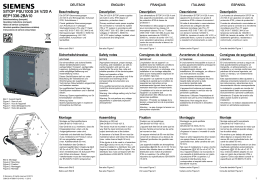
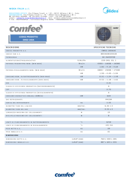
DEUTSCH
SITOP PSU100S
6EP1322-2BA00 12 V / 7 A
6EP1323-2BA00 12 V / 14 A
Betriebsanleitung (kompakt)
Operating Instructions (compact)
Notice de service (compacte)
Istruzioni operative (descrizione sintetica)
Instrucciones de servicio (resumidas)
Bild 1: Ansicht Geräte
Figure 1: View of units
Figure 1: Vue des appareils
Figura 1: Vista degli apparecchi
Figura 1: Vista de aparatos
Beschreibung
ENGLISH
Description
Die SITOP-Stromversorgungen
PSU100S sind Einbaugeräte, Schutzart
IP20, Schutzklasse I.
The PSU100S SITOP power supplies
are built-in units, IP20 degree of
protection, protection class I.
Primär getaktete Stromversorgungen
zum Anschluss an 1-phasiges
Wechselstromnetz (TN-, TT- Netz nach
VDE 0100 T 300 / IEC 364-3) mit
Nennspannungen 120/230 V, 50/60 Hz;
Ausgangsspannung +12 V DC,
potenzialfrei, kurzschluss- und
leerlauffest.
Primary switched-mode power supplies
for connection to 1-phase AC system
(TN, TT system in accordance with
VDE 0100 T 300 / IEC 364-3) with rated
voltages of 120/230 V, 50/60 Hz;
+12 V DC output voltage, isolated, shortcircuit-proof and idling-proof.
FRANÇAIS
Description
Les alimentations SITOP PSU100S sont
des appareils encastrables, en indice de
protection IP20 et de classe de
protection I.
Alimentations à découpage au primaire
pour raccordement au réseau CA
monophasé (réseau TN ou TT selon
VDE 0100 T 300 / CEI 364-3) avec des
tensions nominales de 120/230 V,
50/60 Hz ; tension de sortie +12 V CC,
avec séparation galvanique, protection
contre les courts-circuits et tenue à la
marche à vide.
ITALIANO
Descrizione
Gli alimentatori SITOP PSU100S sono
apparecchi da incasso con grado di
protezione IP20 e classe di sicurezza I.
Si tratta di alimentatori a commutazione
del primario da collegare alla rete
alternata monofase (rete TN, TT
secondo VDE 0100 T 300 / IEC 364-3)
con tensioni nominali 120/230 V,
50/60 Hz, tensione di uscita +12 V DC, a
potenziale libero, a prova di cortocircuito
e resistenti al funzionamento a vuoto.
ESPAÑOL
Descripción
Las fuentes de alimentación SITOP
PSU100S son aparatos empotrables con
grado de protección IP20 y clase de
protección I.
Fuentes de alimentación conmutadas en
primario para la conexión a la red alterna
monofásica (red TN, TT según
VDE 0100 T 300 / IEC 364-3) con
tensiones nominales de 120/230 V,
50/60 Hz; tensión de salida +12 V DC,
aislamiento galvánico, resistentes a
cortocircuito y marcha en vacío.
Siehe auch Bild 1
See also Figure 1
Voir aussi Figure 1
Vedere anche Figura 1
Consulte también Figura 1
Sicherheitshinweise
Safety notes
Consignes de sécurité
Avvertenze di sicurezza
Consignas de seguridad
ACHTUNG
NOTICE
IMPORTANT
ATTENZIONE
ATENCIÓN
Der einwandfreie und sichere Betrieb
dieses Gerätes/Systems setzt
sachgemäßen Transport, sachgemäße
Lagerung, Aufstellung und Montage
sowie sorgfältige Bedienung und
Instandhaltung voraus.
Dieses Gerät/System darf nur unter
Beachtung der Instruktionen und
Warnhinweise der zugehörigen
Technischen Dokumentation eingerichtet
und betrieben werden.
Nur qualifiziertes Personal darf das
Gerät/System installieren und in Betrieb
setzen.
Warnung: Spannungseinstellung nur für
Erstinstallation verwenden
Warnung: keine
Spannungsanpassungen in explosiver
Atmosphäre durchführen.
Bei Ausgangsleistungen über der
Nennleistung (Nutzung Ia,nenn>100 %)
kann der Eingangsstrom Ie den
Nennstrom Ie,nenn übersteigen .
Achtung: Neutralleitersicherung
Appropriate transport, proper storage,
mounting, and installation, as well as
careful operation and service, are
essential for the error-free, safe and
reliable operation of the device/system.
Setup and operation of this
device/system are permitted only if the
instructions and warnings of the
corresponding documentation are
observed.
Only qualified personnel are allowed to
install the device/system and set it into
operation.
Warning: Use voltage setting only for first
installation
Warning: Do not operate voltage
adjustment when an explosive
atmosphere may be present.
In the case of output powers above the
rated power (use Ia,rated>100%) the input
current Ie can exceed the rated current
Ie,rated.
NOTICE ! Neutral conductor fuse
L'exploitation de cet appareil / ce
système dans les meilleures conditions
de fonctionnement et de sécurité
suppose un transport, un stockage, une
installation et un montage adéquats,
ainsi qu'une manipulation soigneuse et
un entretien rigoureux.
Cet appareil / ce système ne peut être
configuré et exploité qu'à condition de
respecter les instructions et les
avertissements figurant dans la
documentation technique
correspondante.
L'installation et la mise en service de
l'appareil / du système doit
impérativement être effectué par des
personnes qualifiées.
Attention : Procéder au réglage de la
tension uniquement lors de la première
installation
Attention : ne pas changer la tension en
atmosphère explosible.
Lorsque la puissance de sortie dépasse
la puissance nominale (Isortie,nom>100 %),
le courant d'entrée Ie peut dépasser le
courant nominal Ie,nom.
Important : protection du conducteur
neutre
Il funzionamento ineccepibile e sicuro di
questo apparecchio/sistema presuppone
un trasporto corretto, un
immagazzinaggio idoneo, una
installazione, un montaggio, un utilizzo e
una manutenzione accurati.
Questo apparecchio/sistema deve
essere installato e impiegato nel pieno
rispetto delle istruzioni e delle
avvertenze riportate nella
documentazione tecnica pertinente.
L'apparecchio/il sistema può essere
installato e messo in servizio solo da
personale qualificato.
Avvertenza: Utilizzare l'impostazione di
tensione solo per la prima installazione
Avvertenza: Non eseguire alcun
adattamento di tensione in atmosfera
esplosiva.
In caso di potenze di uscita superiori alla
potenza nominale (utilizzo Iu,nom>100 %)
la corrente di ingresso Ii potrebbe
superare la corrente nominale Ii,nom.
Attenzione: Fusibile del conduttore di
neutro
El funcionamiento correcto y seguro de
este aparato/sistema presupone un
transporte, un almacenamiento, una
instalación y un montaje conformes a las
prácticas de la buena ingeniería, así
como un manejo y un mantenimiento
rigurosos.
Este aparato/sistema debe ajustarse y
utilizarse únicamente teniendo en cuenta
las instrucciones y advertencias de la
documentación técnica correspondiente.
La instalación y puesta en marcha del
aparato/sistema debe encomendarse
exclusivamente a personal cualificado.
Advertencia: El ajuste de tensión sólo
debe usarse durante la primera
instalación
Advertencia: no realizar adaptaciones de
tensión en atmósferas explosivas.
En caso de potencia de salida superior a
la nominal (si s,nom>100 %), la intensidad
de entrada Ie puede superar a la nominal
Ie,nom .
Atención: Fusible en neutro
Bild 2: Montage
Figure 2: Mounting
Figure 2: Fixation
Figura 2: Montaggio
Figura 2: Montaje
© Siemens, All rights reserved Ⓟ 2012
C98130-A7619-A102-2-6419, 8.2012
1
Montage
Bild 3: Input ①
Figure 3: Input ①
Figure 3: Input ①
Figura 3: Input ①
Figura 3: Entradas ①
Assembling
Montage auf Normprofilschiene
DIN EN 60715-TH35-15/7,5.
Mounted on a standard mounting rail
DIN EN 60715-TH35-15/7,5.
Montage sur rail DIN symétrique
DIN EN 60715-TH35-15/7,5
Das Gerät ist so zu montieren, dass die
Eingangs- und Ausgangsklemmen unten
sind.
The device must be mounted in such a
way that the input and output terminals
are at the bottom.
L'appareil doit être fixé de sorte que les
bornes d'entrée et les bornes de sortie
se trouvent en bas.
Unterhalb und oberhalb des Gerätes
muss mindestens ein Freiraum von je
50 mm eingehalten werden (max.
Kabelkanaltiefe 50 mm).
A clearance of at least 50 mm must be
maintained above and below the device
(max. cable channel depth 50 mm).
Bei Installation des Gerätes in
explosionsgefährdeter Umgebung
( II 3G Ex nA nC IIC T4 Gc) ist dieses
in einen Verteilerkasten mit Schutzart
IP54 oder höher einzubauen. Dieser
Verteilerkasten muss den Anforderungen
der EN 60079-15:2010 entsprechen.
Angewandte Normen: EN 60079-0:2009
und EN 60079-15:2010
If the device is to be used in a hazardous
area ( II 3G Ex nA nC IIC T4 Gc) it
must be installed in a distributor box with
degree of protection IP54 or higher. This
distributor box must correspond with the
specifications of EN 60079-15:2010.
Applicable standards: EN 60079-0:2009
and EN 60079-15:2010
Bild 5: Klemmendaten
Figure 5: Terminal data
Figure 5: Caractéristiques des bornes
Figura 5: Dati dei morsetti
Figura 5: Datos de los bornes
Montaggio su guida profilata
normalizzata DIN EN 60715-TH3515/7,5.
Montaje
Montaje en perfil normalizado
DIN EN 60715-TH35-15/7,5.
L'apparecchio va montato con i morsetti
d'ingresso e quelli di uscita in basso.
El aparato debe montarse de modo que
los bornes de entrada y salida queden
abajo.
Un espace minimal de 50 mm doit être
conservé en dessous et au dessus de
l'appareil (profondeur de goulotte max.
50 mm).
Sopra e sotto l'apparecchio deve restare
uno spazio libero di almeno 50 mm
(profondità max. della canalina dei cavi:
50 mm).
Por encima y por debajo del aparato
debe dejarse un espacio libre de al
menos 50 mm (profundidad máx. del
canal de cables 50 mm).
Les appareils installés en atmosphères
explosibles ( II 3G Ex nA nC IIC T4
Gc) doivent être montés dans un coffret
de distribution avec indice de protection
IP54 ou supérieur. Ce coffret doit
répondre aux spécifications d'EN 6007915:2010.
Nel caso di installazione in aree a rischio
d'esplosione ( II 3G Ex nA nC IIC T4 Gc),
l'apparecchiatura va incorporata in una
cassetta di distribuzione con grado di
protezione IP54 o superiore. La cassetta
di distribuzione deve corrispondere ai
requisiti della norma EN 60079-15:2010.
Si se va a instalar el aparato en una
atmósfera potencialmente explosiva
( II 3G Ex nA nC IIC T4 Gc), deberá
montarse en una caja con grado de
protección IP54 o superior. Dicha caja
deberá cumplir lo especificado en
EN 60079-15:2010.
Normes appliquées : EN 60079-0:2009
et EN 60079-15:2010
Norme impiegate: EN 60079-0:2009 ed
EN 60079-15:2010
Normas aplicadas: EN 60079-0:2009 y
EN 60079-15:2010
See also Figure 2
See also Figure 6
Voir aussi Figure 2
Voir aussi Figure 6
Vedere anche Figura 2
Vedere anche Figura 6
Consulte también Figura 2
Consulte también Figura 6
Anschließen
Connecting
Raccordement
Collegamento
Conexión
Vor Beginn der Installations- oder
Instandhaltungsarbeiten ist der
Hauptschalter der Anlage auszuschalten
und gegen Wiedereinschalten zu
sichern. Bei Nichtbeachtung kann das
Berühren spannungsführender Teile Tod
oder schwere Körperverletzung zur
Folge haben. Die Betätigung des
Potenziometers ist nur mittels isoliertem
Schraubendreher zulässig. Für die
Installation der Geräte sind die
einschlägigen länderspezifischen
Vorschriften zu beachten.
Wichtiger Hinweis: Eingangsseitig ist ein
Leitungs- oder Motorschutzschalter
vorzusehen.
Der Anschluss der
Versorgungsspannung (1 AC 120/230 V)
muss gemäß IEC 60364 und EN 50178
ausgeführt werden.
WARNING
Before installation or maintenance work
can begin, the system's main switch
must be switched off and measures
taken to prevent it being switched on
again. If this instruction is not observed,
touching live parts can result in death or
serious injury. It is only permissible to
use an insulated screwdriver when
actuating the potentiometer. For
installation of the devices, the relevant
country-specific regulations must be
observed.
Important note: A minitiature circuit
breaker or motor circuit breaker must be
provided at the input side.
The supply voltage (1 AC 120/230 V)
must be connected in accordance with
IEC 60364 and EN 50178.
ATTENTION
Avant de commencer les travaux
d'installation ou de maintenance, couper
l'interrupteur général de l'installation et le
condamner pour empêcher la remise
sous tension. Le non-respect de cette
consigne peut entraîner la mort ou des
blessures graves en cas de contact avec
des pièces sous tension. Actionner le
potentiomètre uniquement à l'aide d'un
tournevis isolé. L'installation des
appareils doit se faire en conformité avec
les prescriptions nationales.
Remarque importante : un disjoncteur de
ligne ou disjoncteur moteur doit être
prévu en entrée.
Le raccordement de la tension
d'alimentation (1ph. 120/230 V) doit être
effectué conformément à CEI 60364 et
EN 50178.
AVVERTENZA
Prima dell'inizio dei lavori di installazione
o manutenzione è necessario disinserire
l'interruttore principale dell'impianto e
assicurarlo contro la reinserzione. In
caso di mancata osservanza, il contatto
con parti sotto tensione può provocare la
morte o gravi lesioni personali. È
consentito azionare il potenziometro solo
utilizzando un cacciavite isolato. Per
l'installazione degli apparecchi occorre
osservare le normative nazionali vigenti.
Avvertenza importante: sul lato
d'ingresso si deve predisporre un
interruttore magnetotermico o un
salvamotore.
L'allacciamento della tensione di
alimentazione (1 AC 120/230 V) deve
essere eseguito in conformità alle norme
IEC 60364 ed EN 50178.
ADVERTENCIA
Antes de comenzar los trabajos de
instalación o mantenimiento, se deberá
abrir el interruptor principal del
cuadro/tablero y protegerlo para evitar
su cierre. Si no se observa esta medida,
el contacto con piezas bajo tensión
puede provocar la muerte o lesiones
graves. El potenciómetro solo deberá
girarse usando un destornillador aislado.
A la hora de instalar los aparatos, se
tienen que observar las disposiciones o
normativas específicas de cada país.
Nota importante: en el lado de entrada
debe preverse un automático
magnetotérmico o un guardamotor.
La conexión de la alimentación
(1 AC 120/230 V) debe efectuarse
conforme a las normas IEC 60364 y
EN 50178.
Siehe auch Bild 3
Siehe auch Bild 4
Siehe auch Bild 5
See also Figure 3
See also Figure 4
See also Figure 5
Voir aussi Figure 3
Voir aussi Figure 4
Voir aussi Figure 5
Vedere anche Figura 3
Vedere anche Figura 4
Vedere anche Figura 5
Consulte también Figura 3
Consulte también Figura 4
Consulte también Figura 5
Aufbau
Structure
Constitution
Struttura
Diseño
①
②
③
④
⑤
⑥
⑦
⑧
AC-Eingang
DC-Ausgang
Meldekontakt
Potenziometer 11,5 – 15,5 V
Kontrollleuchte (12 V O.K.)
Hutschienenentriegelung
Konvektion
Freiraum oberhalb/unterhalb
Siehe auch Bild 6
2
Montaggio
Siehe auch Bild 2
Siehe auch Bild 6
WARNUNG
Bild 4: Output ②, Meldekontakt ③
Figure 4: Output ②, signaling contact ③
Figure 4: Output ②, contacts de signalisation ③
Figura 4: Output ②, contatto di segnalazione ③
Figura 4: Salidas ②, contacto de señalización ③
Fixation
①
②
③
④
⑤
⑥
⑦
⑧
AC input
DC output
Signaling contact
Potentiometer 11.5 - 15.5 V
Indicator light (12 V OK)
Mounting rail release
Convection
Clearance above/below
See also Figure 6
①
②
③
④
⑤
⑥
⑦
⑧
Entrée CA
Sortie CC
Contact de signalisation
Potentiomètre 11,5…15,5 V
Témoin de tension (12 V O.K.)
Déverrouillage de la fixation au rail
Convection
Espace libre au dessus/en dessous
Voir aussi Figure 6
①
②
③
④
⑤
⑥
⑦
⑧
Ingresso AC
Uscita DC
Contatto di segnalazione
Potenziometro 11,5 – 15,5 V
Spia di controllo (12 V O.K.)
Sbloccaggio dalla guida profilata
Convezione termica
Spazio libero superiore/inferiore
Vedere anche Figura 6
①
②
③
④
⑤
⑥
⑦
⑧
Entrada AC
Salida DC
Contacto de señalización
Potenciómetro 11,5 - 15,5 V
Lamparita de control (12 V O.K.)
Desmontaje de perfil sin herramientas
Convección
Espacio libre arriba/abajo
Consulte también Figura 6
C98130-A7619-A102-2-6419, 8.2012
Betriebsmodus
Modo operativo
Modo de servicio
Signaling
Signalisation
Segnalazione
Señalización
⑤ LED grün: Ausgangsspannung OK
⑤ LED is green: Output voltage OK
⑤ LED verte : Tension de sortie OK
⑤ LED verde: tensione di uscita OK
⑤ LED verde: Tensión de salida OK
Meldesignale
Alarm signals
Signaux
Segnali
Señalización
③ Meldekontakt: Ausgang OK
③ Signaling contact: Output OK
Contact rating
30 V AC/0.5 A, 60 V DC/0.3 A,
30 V DC/1 A
③ Contact de signalisation : Sortie OK
30 V CA/0,5 A, 60 V CC/0,3 A,
30 V CC/1 A
③ Contatto di segnalazione: uscita OK
Caricabilità del contatto
AC 30 V/0,5 A DC 60 V/0,3 A
DC 30 V/1 A
③ Contacto de señalización: Salida OK
Siehe auch Bild 4
See also Figure 4
Voir aussi Figure 4
Technische Daten
Technical data
Caractéristiques techniques Dati tecnici
6EP1322-2BA00
12 V/7 A
C98130-A7619-A102-2-6419, 8.2012
Mode de fonctionnement
Signalisierung
Kontaktbelastbarkeit
AC 30 V/0,5 A; DC 60 V/0,3 A;
DC 30 V/1 A
Bild 6: Gesamtaufbau
Figure 6: Overall structure
Figure 6: Constitution
Figura 6: Struttura completa
Figura 6: Diseño general
Operating mode
6EP1323-2BA00
12 V/14 A
6EP1322-2BA00
12V/7A
6EP1323-2BA00
12V/14A
6EP1322-2BA00
12 V/7 A
Vedere anche Figura 4
6EP1323-2BA00
12 V/14 A
6EP1322-2BA00
12 V/7 A
Capacidad de carga de los contactos
30 V/0,5 A AC, 60 V/0,3 A DC,
30 V/1 A DC
Consulte también Figura 4
Datos técnicos
6EP1323-2BA00
12 V/14 A
6EP1322-2BA00
12 V/7 A
6EP1323-2BA00
12 V/14 A
① Eingangsgrößen
① Input variables
① Valeurs d'entrée
① Grandezze di ingresso
① Magnitudes de entrada
Eingangsnennspannung Ue nenn:
1 AC 120/230 V 50/60 Hz
Rated input voltage Uin rated:
1 AC 120/230V 50/60Hz
Tension d'entrée nominale Ue nom :
CA 120/230 V 50/60 Hz
Tensione nominale di ingresso Ui nom:
1 AC 120/230 V 50/60 Hz
Tensión nominal de entrada Ue nom:
1 AC 120/230 V 50/60 Hz
Spannungsbereich:
1 AC 85-132/170-264 V
Voltage range:
1 AC 85-132/170-264V
Plage de tension :
1 AC 85-132/170-264 V
Campo di tensione:
1 AC 85-132/170-264 V
Rango de tensión:
1 AC 85-132/170-264 V
Eingangsnennstrom Ie nenn
bei Nennlast:
Rated input current Ie rated
at rated load:
Courant d'entrée nominal Ie nom
à charge nominale :
Corrente nominale di ingresso Ii nom con
carico nominale:
Intensidad nominal de entrada Ie nom con
carga nominal
1/1,7 A
1/1.7A
1 / 1,7 A
1/1,7 A
1/1,7 A
1,5/3,1 A
1.5/3.1A
1,5 / 3,1 A
1,5/3,1 A
1,5/3,1 A
Eingangssicherung: intern
Input fuse: Internal
Fusible d'entrée : interne
Fusibile di ingresso: interno
Fusible de entrada: interno
Empfohlener Leitungsschutzschalter:
Charakteristik C: 6 / 10 A
Recommended miniature circuit breaker:
Characteristic C: 6/10A
Disjoncteur recommandé :
caractéristique C : 6 / 10 A
Interruttore magnetotermico consigliato:
caratteristica C: 6 / 10 A
Automático magnetotérmico
recomendado: curva C 6 / 10 A
Leistungsaufnahme (Wirkleistung)
Volllast (typisch)
Power consumption (active power)
full load (typical)
Puissance absorbée (puissance active),
pleine charge (typique) :
Potenza assorbita (potenza attiva) a
pieno carico (tipica)
Consumo (potencia activa) a plena
carga (típico)
99 W
99W
99 W
99 W
99 W
196 W
196W
196 W
196 W
196 W
② Ausgangsgrößen
② Output variables
② Valeurs de sortie
② Grandezze di uscita
② Magnitudes de salida
Ausgangsnennspannung Ua nenn:
Rated output voltage Uout rated:
Tension de sortie nominale Us nom :
Tensione nominale di uscita Uu nom:
Tensión nominal de salida Us nom:
12 V
12V
12 V
12 V
12 V
12 V
12V
12 V
12 V
12 V
Einstellbereich: Einstellung über
Potenziometer ④ an der
Gerätevorderseite (in V)
Setting range: Set using a
potentiometer ④ at the front of the
device (in V)
Plage de réglage : Réglage par
potentiomètre ④ sur la face avant de
l'appareil (en V)
Campo di regolazione: regolazione
tramite potenziometro ④ sul lato
frontale dell'apparecchio (in V)
Rango de ajuste: Ajuste por
potenciómetro ④ en el frente (en V)
11,5...15,5
11.5...15.5
11,5...15,5
11,5...15,5
11,5...15,5
11,5...15,5
11.5...15.5
11,5...15,5
11,5...15,5
11,5...15,5
Ausgangsnennstrom Ia nenn:
Rated output current Iout rated:
Courant de sortie nominal Isortie nom:
Corrente nominale di uscita Iu nom:
Corriente nominal de salida Is nom:
7A
7A
7A
7A
7A
14 A
14A
14 A
14 A
14 A
Extra Power beim Einschalten und im
Betrieb:
150 % Ia nenn für 5 s (pro min)
Extra power during switch-on and
operation:
150% Ia rated for 5 s (per min)
Puissance supplémentaire à la mise en
marche et en service :
150 % Isortie nom pendant 5 s (par min)
Extra Power all'inserzione e in esercizio:
150 % Iu nom per 5 s (al minuto)
Potencia adicional al conectar y en
servicio:
150 % Is nom durante 5 s (por min)
10,5 A
10.5A
10,5 A
10,5 A
10,5 A
21 A
21A
21 A
21 A
21 A
Umgebungsbedingungen
Ambient conditions
Conditions ambiantes
Condizioni ambientali
Condiciones ambientales
Temperatur für Betrieb: -10...+70 °C;
Temperature for operation: -10...+70°C;
Température de fonctionnement -10...+70 °C
Temperatura in esercizio: -10...+70 °C;
Temperatura de funcionamiento: -10...+70 °C;
Derating: ab +55 °C: 5 % Ia,nenn/K;
Eigenkonvektion
Derating: from +55°C: 5% Ia,rated/K;
Natural convection
Déclassement à partir de +55 °C
5 % Isortie,nom/K; Convection naturelle
Derating: a partire da +55 °C: 5 % Iu,nom/K;
Convezione naturale
Reducción de potencia: a partir de
+55 °C: 5 % Is,nom/K; Convección natural
Schutzfunktion
Protective function
Fonction de protection
Funzione di protezione
Función de protección
Strombegrenzung bei permanenter
Überlast (>5 s),
Ansprechwert: <1,6 × Ia nenn,
ausgenommen Extra Power
Current limitation at permanent overload
(>5 s),
response value: <1.6 × Ia rated,
except Extra Power
Limitation de courant pour surcharge
permanente (> 5 s),
seuil de réponse :
< 1,6 × Isortie nom, sauf Extra Power
Limitazione di corrente con sovraccarico
permanente (>5 s),
valore di intervento: <1,6 × Iu nom,
escluso Extra Power
Limitación de corriente con sobrecarga
permanente (> 5 s),
valor de reacción: < 1,6 × Is nom,
exceptuando Extra Power
Kennlinie der Strombegrenzung stetig
abfallend.
Characteristic of current limitation
constantly dropping
Courbe de limitation de courant
décroissante
Caratteristica della limitazione di
corrente costantemente decrescente
Característica de limitación de corriente:
monótona decreciente
Abmessungen
Breite × Höhe × Tiefe in mm:
Dimensions
width× height × depth in mm:
Dimensions
Largeur × hauteur × profondeur en mm :
Dimensioni
larghezza x altezza x profondità in mm:
Dimensiones
Anchura x altura × profundidad en mm:
50x125x125
50x125x125
50x125x125
50x125x125
50x125x125
70x125x125
70x125x125
70x125x125
70x125x125
70x125x125
3
Zubehör
Accessoires
Accessori
Accesorios
Funktionserweiterung durch
Ergänzungsmodule Redundanzmodul,
Puffermodul, Diagnosemodul SITOP
select oder DC USV möglich
Function expansion possible using the
additional modules redundancy module,
buffer module, diagnostics module
SITOP select or DC UPS
L'extension fonctionnelle est possible au
moyen des modules d'extension module
de redondance, module tampon, module
de diagnostic SITOP select ou DC USV
(ASI)
Ampliamento delle funzioni tramite
moduli aggiuntivi: modulo di ridondanza,
modulo buffer, modulo di diagnostica
SITOP select o modulo DC UPS
Es posible una ampliación funcional
mediante módulos complementarios:
módulo de redundancia, módulo de
respaldo, módulo de diagnóstico SITOP
select o SAI DC
www.siemens.de/sitop
www.siemens.com/sitop
www.siemens.com/sitop
www.siemens.com/sitop
www.siemens.de/sitop
Entsorgungsrichtlinien
Verpackung und Packhilfsmittel sind
recyclingfähig und sollten grundsätzlich
der Wiederverwertung zugeführt werden.
Das Produkt selbst darf nicht über den
Hausmüll entsorgt werden.
Service und Support
4
Accessories
Disposal guidelines
Packaging and packaging aids can and
must always be recycled. The product
itself may not be disposed of by means
of domestic refuse.
Service and Support
Directives de recyclage
L'appareil et son emballage sont tous
recyclables et doivent donc être traités
par une filière de recyclage. Il est interdit
de se débarrasser de l'appareil via les
déchets domestiques.
SAV et assistance
Direttive sullo
smaltimento
L'imballaggio e i materiali ausiliari di
imballaggio utilizzati sono riciclabili e
devono quindi essere destinati al
riciclaggio. Questo prodotto non deve
essere smaltito con i rifiuti ordinari.
Service & Support
Directivas de eliminación
de residuos
Todo el material usado para el embalaje
es reciclable, por lo que debería
separarse para su reutilización. El
producto propiamente dicho no deberá
eliminarse a través de la basura
doméstica.
Servicio técnico y asistencia
http://support.automation.siemens.com
http://support.automation.siemens.com
http://support.automation.siemens.com
http://support.automation.siemens.com
http://support.automation.siemens.com
Telefon: + 49 (0) 911 895 7222
Telephone: + 49 (0) 911 895 7222
Téléphone : + 49 (0) 911 895 7222
Telefono: + 49 (0) 911 895 7222
Teléfono: + 49 (0) 911 895 7222
C98130-A7619-A102-2-6419, 8.2012
Scarica