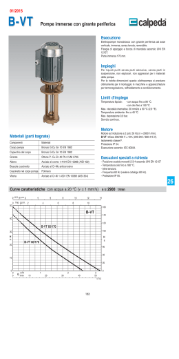
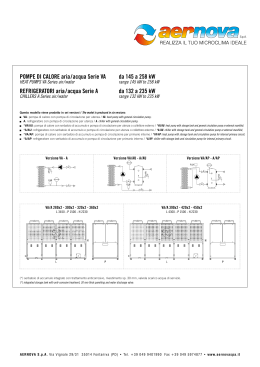
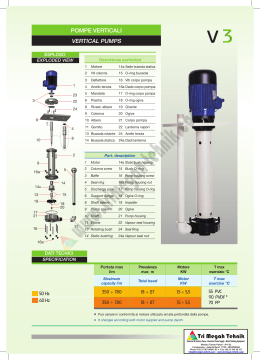
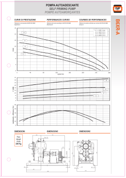
Pompe Centr. 07/06 28-07-2006 19:44 Pagina 1
C
M
Y
CM
MY
CY CMY
K
Ed. PC '06
®
©
7/06
3
alimentari - anticorrosive - sanitizzabili
corrosion-proof - food - sterilizing
TECNINOX S.r.l.
Via Emilia 89/A
Loc. Sanguinaro 43015 NOCETO (PARMA) - ITALY
Tel.+39 0521 825324 - Fax +39 0521 825257
http:/www.tecninox.it
E-MAIL: [email protected]
Colori compositi
POMPE CENTRIFUGHE serie C e SP
CENTRIFUGAL PUMPS series C and SP
Pompe Centr. 07/06 28-07-2006 19:44 Pagina 2
C
POMPE CENTRIFUGHE SANITARIE
A
M
Y
CM
MY
CY CMY
K
SERIE SP la pompa su basamento con alta performance
the base-mounted pump you don’t have to pamper
Pompe sanitarie centrifughe a monoblocco in acciaio inox AISI.316
lucidate internamente ed esternamente. Forte resistenza alla corrosione
e per impieghi ove sia richiesta la massima igienicità del prodotto senza
pericolo di contaminazione.
Migliaia di pompe sono oggi in servizio nei vari settori dell'industria dando
altissime rese e grandi affidabilità. La pompa è tutta smontabile manualmente
(compresa la girante) senza l'ausilio di attrezzi. Internamente è stata studiata
per non lasciare residui del prodotto trattato. La tenuta è meccanica “D” o “F”
(standard) oppure “DG” o “H”
Le nostre pompe centrifughe sanitarie sono indentificate con il simbolo 3A
(Committees of Intemational Association of Milk Food and Environmetal Sanitarians
U.S. Public Health Service and Dairy Industry Committe). È la massima garanzia
di qualita!
Il marchio 3A, è in conformità con ASME Food Drug and Beverage Equipment
Standard ANSI/ASME F.2.1.1982.
L’usura dell’abero è ridotta al minimo:
gli alberi vengono lavorati con macchine
utensili ad alta pressione e sono progettati
per funzionare a 1800 o 3600 giri al
minuto.
Shaft wear is minimized: Shafts are
precision machined, designed for
operation at 1800 or 3600 RPM.
Sanitary and centrifugal pumps in stainless steel AISI 316
internally and externally polished. Long corrosion resistance and for uses where
the maximum hygiene of the product is requested without danger of contamination.
Thousands of pumps are to-day working in different industrial sectors giving high
yields and great reliability. The pump is completely manually detachable (including
impeller) without the help of tools. Internally studied to avoid residuals of the
treated product. Mechanic seal D&F (standard) or DG & H.
The sanitary centrifugal pumps in stainless steel are identified with the symbol
3A (Committees of the InternaUonal Association of Milk, Food and Environmental
Sanitariens U.S. Public Health Service and Dairy Industry Committee), which is
the maximum quality guarantee.
3A marked items are also in compliance with ASME Food, Drug and Beverage
Equipment Standard ANSI/ASME F.2.1-1982.
Possibilità di pompare prodotti viscosi
e caldi: il TIPO F è costituito da una
tenuta meccanica esterna bilanciata con
attacco flussaggio d’acqua; è consigliata
per il pompaggio di prodotti viscosi o ad
alta temperatura fino a 95°C e per
operazioni effettuate sottovuoto fino a 355
MM Hg (guarnizione identica al tipo D ma
dotata di attacco per il flussaggio con
acqua)
Pump hot, tacky products: TYPE F
exsternal balanced seal with water
cascading attachment - recommended
for pumping tacky or hot products up to
95°C and for vacuum applications to 355
MM Hg. (Seal identical to Type D, but
equipped with water cascade.)
L’operazione di pompaggio e più
regolare, grazie all’uso di una girante
aperta curvata all’indietro, facile da pulire.
Smoother pumping performance results
from use of easy-to clean, open type,
backward curved impeller.
Progettata per l'uso nei sistemi C.l.P. (clean-in-place) con la sanificazione automatica di tutta l'area a contatto del prodotto (parte in verde vedi rif.A)
U.S. patent N. 3.481.273
Designed for use C.l.P. installations This feature offers effortless self-cleaning with no dismantling or take-down. The sanitizing of all product contact
areas is automatic (A) U.S. patent No. 3,481,273
Tipo
Type
C-114
C-216
C-218
C-328
C-4410
Ingresso
Inlet
11/2” o
2” o
2” o
3” o
4” o
2”
21/2”
3”
4”
6” *
Uscita
Outlet
11/2”
11/2”
11/2”
2”
4”
• connessioni di ingresso allargate Tri Clamp ® o attacchi DIN 11851
(disponibili su richiesta)
• connessioni di uscita DIN 11851 (disponibili su richiesta)
Max Ø girante
Max Impeller Ø
4”
6”
8”
8”
10”
MECHANICAL SPECIFICATIONS
ELECTRIC MOTOR:
• Poles 2 or 4 (rpm 2900/1450)
• Asynchronous three-phase V= 220/38~Hz= 50 up to 5, 5 Kw.
included, over 5,5 Kw V= 380/660 - Hz= 50
• Ex on request (explosion proof) and special voltage
* Con riduzione eccentrica 6” x 5” in ingresso (5” sul casing)
With 6" x 5” eccentric reducer on inlet (casing/inlet is 5”)
CARATTERISTICHE MECCANICHE
MATERIALS FOR CONSTRUCTION:
• Pump body, back plate, pin, impeller and shaft manufactured in AISI
316L stainless steel
• Mechanical seals (see specifications on page 3)
• Adapter for motor/pump manufactured in treated cast iron (on request
in AISI 304 stainless steel)
• Seal guard, manufactured in AISI 304
• Cover motor with ventilation holes, manufactured in AISI 304
• Body gaskets: Buna/N (standard) - Viton*, EPDM, PTFE and Karlez
are available on request
MOTORE ELETTRICO:
• 2 o 4 poli (rpm= 2900/1450)
• Asincrono trifase V= 220/380-Hz=50 fino a 5,5 Kw compreso,
oltre 5,5 Kw V= 380/660 - Hz=50
• Su richiesta Ex (explosion proof) e tensioni speciali
MATERIALI DI COSTRUZIONI:
• Corpo pompa, piatto posteriore, spina girante, girante e albero in
acciaio inox AISI-316L
• Tenute meccaniche (vedi specifiche a pag. 3)
• Campana di collegamento pompa/motore in ghisa trattata (su richiesta
inox AISI 304)
• Carter di protezione organi rotanti, inox AISI 304
• Capot motore con feritoie di ventilazione, inox AISI 304
• Guarnizioni corpo: Buna/N (standard) - Viton*, EPDM, PTFE e Karlez
sono disponibili su richiesta.
PORT CONNECTIONS:
• Tri Clamp ® (standard)
• Enlarged inlet casing Tri Clamp ® or DIN 11851 connection (available
on request)
• Outlet connections DIN 11851 (available on request)
®
CONNESSIONI:
• Tri Clamp ® (standard)
(* DU PONT REGISTERED TRADEMARK)
®
3
Colori compositi
Lunga durata dei cuscinetti: garantita
da cuscinetti a sfera sovradimensionati e
da lubrificazione forzata. Il lubrificante in
eccesso viene eliminato. Il grasso viene
spurgato senza dover smontare dei
componenti.
Extended bearing life is assured by
oversized ball bearings and flush through
lubrication. Overlubrication is eliminaded.
Grease is purged, without takedown.
1
3
Maggiore durata delle tenute e tempi
morti inferiori: una tenuta bilanciata
idraulicamente (tipo D, DG, ed F) riduce
la pressione sulla superficie di tenuta,
garantendo un tempo di usura più lungo
e una maggiore efficienza. Si può
scegliere tra le guarnizioni standard o
speciali per soddisfare le proprie
specifiche necessità di pressione,
temperatura o prodotto.
Longer seal life and less downtime:
Hydraulically balanced seal (Type D, DG,
& F Seals) reduces pressure at sealing
surface providing for longer wear and
greater efficiency. Select from standard
or special seals to meet your pressure,
temperature, or product requirements.
Nessun smontaggio per le operazioni
di pulizia: il design, unico nel suo genere,
con albero a scanalature interne convoglia
il prodotto di sanificazione verso tutti i
punti critici, per una pulizia localizzata, in
sistemi C.I.P.
No takedown for cleaning: Unique
groove-in-shaft design routes sanitizer to
all critical areas for clean-in- place.
10
Lo smontaggio della pompa è
un’operazione semplice e veloce, che
non richiede attrezzi: il corpo della
pompa è fissato con un clamp ad apertura
rapida. La girante è fissata con un fermo
a spina per effetto della forza centrifuga.
Pump takedown is easy, fast - no tools
required: Casing is secured with quickopening clamp. Impeller is centrifugally
secured with a retainer clip.
Pompe Centr. 07/06 28-07-2006 19:44 Pagina 6
C
SERIE C
Maggiore durata delle tenute e tempi
morti inferiori: una tenuta bilanciata
idraulicamente (tipo D, DG, ed F) riduce
la pressione sulla superficie di tenuta,
garantendo un tempo di usura più lungo
e una maggiore efficienza. Si può
scegliere tra le guarnizioni standard o
speciali per soddisfare le proprie
specifiche necessità di pressione,
temperatura o prodotto.
Longer seal life and less downtime:
Hydraulically balanced seal (Type D, DG,
& F Seals) reduces pressure at sealing
surface providing for longer wear and
greater efficiency. Select from standard
or special seals to meet your pressure,
temperature, or product requirements.
per il massimo dell’efficienza
for top operating efficiency
Possibilità di pompare prodotti viscosi
e caldi: il TIPO F è costituito da una
tenuta meccanica esterna bilanciata con
attacco flussaggio d’acqua; è consigliata
per il pompaggio di prodotti viscosi o ad
alta temperatura fino a 95°C e per
operazioni effettuate sottovuoto fino a 355
MM Hg (guarnizione identica al tipo D ma
dotata di attacco per il flussaggio con
acqua)
Pump hot, tacky products: TYPE F
exsternal balanced seal with water
cascading attachment - recommended
for pumping tacky or hot products up to
95°C and for vacuum applications to 355
MM Hg.(Seal identical to Type D, but
equipped with water cascade.)
M
Y
CM
MY
CY CMY
K
SANITARY CENTRIFUGAL PUMPS
L’operazione di pompaggio e più
regolare, grazie all’uso di una girante
aperta curvata all’indietro, facile da pulire.
X
X, Y, Z = su richiesta
= upon request
Smoother pumping performance results
from use of easy-to clean, open type,
backward curved impeller.
Drenaggio su richiesta (vedi pag. 3) - Dreinage on request (see pag. 3)
Y
Z
capot in option
* Connessione DIN -11851 - DIN -11851 Connection
®
3
Colori compositi
Nessun smontaggio per le operazioni
di pulizia: il design, unico nel suo genere,
con albero a scanalature interne convoglia
il prodotto di sanificazione verso tutti i
punti critici, per una pulizia localizzata, in
sistemi C.I.P.
No takedown for cleaning: Unique
groove-in-shaft design routes sanitizer to
all critical areas for clean-in- place.
Lo smontaggio della pompa è un’operazione semplice e veloce, che non
richiede attrezzi: il corpo della pompa è
fissato con un clamp ad apertura rapida.
La girante è fissata con un fermo a spina
per effetto della forza centrifuga.
Pump takedown is easy, fast - no tools
required: Casing is secured with quickopening clamp. Impeller is centrifugally
secured with a retainer clip.
A
B
C
C*
D
D*
E
F
G
H
I
L
L1
M
N
øU
11/2”
11/2”
252
276
428
455
40
40
47
47
92
92
98
98
140
150
156
174
67
67
125
140
230
290
364
364
371
371
102
102
81
81
16
16
2”
2”
2”
2”
11/2”
11/2”
11/2”
11/2”
276
298
310
377
480
522
570
595
48
48
48
48
55
55
55
55
114
114
114
114
121
121
121
121
150
160
175
195
174
196
227
260
94
94
94
94
140
160
190
216
290
340
340
370
433
433
433
433
439
439
439
439
127
127
127
127
107
107
107
107
25
25
25
25
90
100
112
132
160
180
2”
2”
2”
2”
2”
2”
11/2”
11/2”
11/2”
11/2”
11/2”
11/2”
285
298
310
377
445
484
470
500
540
580
755
805
48
48
48
48
48
48
55
55
55
55
55
55
140
140
140
140
140
140
146
146
146
146
146
146
167
160
175
195
220
240
172
196
226
260
304
337
121
121
121
121
121
121
160
160
190
216
254
279
290
340
340
370
485
485
487
487
487
487
487
487
494
494
494
494
494
494
152
152
152
152
152
152
140
140
140
140
140
140
35
35
35
35
35
35
SP/C328
100
112
132
160
180
3”
3”
3”
3”
3”
2”
2”
2”
2”
2”
298
310
377
445
484
518
558
598
733
870
56
56
56
56
56
69
69
69
69
69
140
140
140
140
140
146
146
146
146
146
167
175
195
220
220
196
226
260
304
340
121
121
121
121
121
160
190
216
254
300
340
340
370
485
675
503
503
503
503
503
516
516
516
516
516
152
152
152
152
152
140
140
140
140
140
35
35
35
35
35
SP/C4410
-
4”
4”
-
-
83
96
177
191
-
-
152
-
-
537
549
203
183
35
TYPE
MOTOR
Ø IN
Ø OUT
SP/C114
80
90
11/2”
11/2”
SP/C216
90
100
112
132
SP/C218
Dimensioni approssimative - Dimensions are approximate
®
9
2
3
Pompe Centr. 07/06 28-07-2006 19:44 Pagina 3
C
M
Y
CM
MY
CY CMY
K
TENUTE MECCANICHE e loro applicazioni
CODICE D’ORDINE
MECHANICAL SEALS AND THEIR APPLICATIONS
“D”
TYPE D
Tipiche applicazioni: latte - bevande, settore alimentare e conserviero, e su CIP di lavaggio
TYPE D
Typical applications: milk - beverage, food and tomato sauce processing, and on washing
CIP
“F”
C
SP
For correct order please state the working data of the
pumps (for verification of our technicians)
Ex.: • Q (Flow Rate in l/h)
• H (Head in m/H2O)
• Treated product, temperature and Viscosity
• N.P.S.H. (Net Positive Suction Head)
Motore (vedere diagrammi)
Motor (See curves chart)
ESEMPIO:
MODEL NUMBER EXAMPLE:
TYPE F
Come “D” ma su applicazioni con vuoto, fino a 355 mm hg, prodotti caldi max 95°C anche
densi
ORDER INFORMATION
Per una corretta ordinazione, indicare sempre i dati di
esercizio delle pompe (necessari per una verifica da
parte dei ns. tecnici)
Es.; • Q (portata in litri)
• H (Prevalenza in mH2O)
• Prodotto trattato, temperatura e viscosità
• N.P.S.H. (Battente positivo netto
sull'aspirazione)
Ø Girante (vedere diagrammi)
Impeller Ø (See curves chart)
C - 328 - M - D - HP= 10 - 4 poli - V = 220/380 - Hz = 50
TYPE F
As "D" is recommended for tacky or hot products up 95°C max and for vacuum application
to 355 mm hg
Ø = 7”
Tipo di tenuta: D = Tenuta esterna, F = Tenuta esterna con lubrificazione ad acqua, DG = Tenuta
esterna con anello statico in SC, C, o T.C. (WFI application), H = Tenuta doppia flussata (WFI application)
Type of Seal: D = External balanced seal, F = External balanced seal cascading water, DG = External
balanced with static ring SC, or C, or T.C. (WFI application), H = Double seal fluxing (WFI application),
Attacchi: M = Tri-Clamp® (standard), G = DIN. - 11851 (su richiesta)
Port connections: M = Tri-Clamp® (standard), G = DIN. - 11851 (upon request)
“DG”
Grandezza pompa = 114 - 216 - 218 -328 - 4418 (vedere diagrammi)
Pump size = 114 - 216 - 218 - 328 - 4418 (See curves chart)
TYPE DG
Con anello statico in SC silicon carbide (standard), CE ceramica, TC tungsteno carbide.
Per applicazioni con acque per uso farmaceutico WFI e P.W.
TYPE DG
With static ring in silicon carbide (standard), CE ceramic, TC tungsten carbide. For
applications with water for pharmaceutical use WFI and P.W.(pure water)
KIT RICAMBI
Serie pompa = C (monoblocco) - SP (su base)
Pump series = C (Monobloc) - SP (Base mounted)
SPARE PARTS KIT
Specificare sempre nell’ordine il tipo di pompa
With your order please state the requested type of pump
“H”
TYPE H . John Crane /9 - Consigliata solo su pompe SP
Tenuta meccanica doppia flussata con acqua pura
- Per applicazioni per uso farmaceutico WFI ove sia richiesta la barriera
TYPE H . John Crane /9 - Recommended only on SP pumps
Double mechanical seal with pure water pressurized
- For applicatios with water for pharmaceutical use WFI where the barrier is required
KIT n. 1
KIT n. 2
KIT n. 3
Questo Kit comprende tutti quei componenti
che vengono sostituiti frequentemente:
This stand by kit contains all components that are
most frequently replaced:
Questo Kit è consigliato per chi dispone di più
pompe TRI-FLO:
This multi-pumps kit is suggested for user who are
operating more than one TRI-FLO pumps.
Questo Kit contiene una tenuta meccanica completa:
This seal stand by kit is contains a complete balanced
rotary carbon seal assembly.s
1 - Guarnizione corpo rif. 90 (Casing gasket)
1 - OR di tenuta rif. 80-B (Seal o-ring)
1 - Tenuta in grafite rif. 80 (Carbon seal)
1 - Spina girante rif. 24 (Impeller pin)
3 - Guarnizione corpo rif. 90 (Casing gasket)
3 - OR di tenuta rif. 80-B (Seal o-ring)
3 - Tenuta in grafite rif. 80 (Carbon seal)
1 - Tenuta in grafite rif. 80 (Carbon seal)
1 - OR di tenuta rif. 80-B (Seal o-ring)
1 - Molla rif. 80-C (Spring)
1 - Collare di guida rif. 80-A (Drive collar)
Selezione tenuta meccanica per applicazioni in WFI e P.W.
Mechanical seal selection for applications in WFI and pure water.
DG
90°
45°
H
WFI con barriera
WFI with barrier
WFI senza barriera
WFI without barrier
USP acqua con barriera
USP water with barrier
USP acqua senza barriera
USP water without barrier
OPTION DRENAGGIO: 3/4” TC - 114 / 216
1” TC - 218 / 328 / 4410
= non consigliata - not recommended
= consigliata - recommended
®
3
Colori compositi
®
3
8
3
Pompe Centr. 07/06 28-07-2006 19:44 Pagina 5
C
mt.
(H)
K
10
51/2
6 1/2"
36 6"
51/2
20
15
71/2
3
50%
7"
55%
8"
61 71/2"
55%
73
48
C/SP-218
• POMPA
PUMP
• VELOCITÀ
2900 R.P.M.
SPEED
• ENTRATA
3"
INLET
• USCITA
11/2"
OUTLET
HP
50%
C/SP-218
• POMPA
PUMP
• VELOCITÀ
2900 R.P.M.
SPEED
• ENTRATA
2"
INLET
• USCITA
11/2"
OUTLET
71/2
3
36 6"
CY CMY
CURVE CHART
15
10
6 1/2"
MY
CURVE CHART
7"
48
CM
DIAGRAMMI DI SCELTA
40%
55%
71/2"
61
50%
8"
40%
73
20%
30%
HP
Y
DIAGRAMMI DI SCELTA
20%
30%
mt.
(H)
M
7,6
24
12
3
1514
90
1892
113
2270
136
2649
159
3028
181
N.P.S.H. = MT.
6
1135
68
2270
136
3406 Lt/1’ (Q)
204 m 3/h (Q)
2649
159
Lt/1’
m 3/h
C/SP-4410
113
6,8
9,0
6"
7,6
3
/4
1
/3
5"
50%
50%
40%
25%
264
16
Lt/1’
m 3/h
0,9
0,6
0,6
0,3
0
0
C/SP-216
37
2,2
75
4,5
113
6,8
4 1/2"
9,0
6"
7,5 51/2"
3
1,5
0,9
0,6
12
0,3
1135
68
1514
90
1892
113
2270
136
2649
159
Lt/1’
m 3/h
(Q)
(Q)
1
/4
1
/6
3,0 4"
1,5
0,9
0,6
0,3
151
9
227
13
302
18
378
22
302
18
Lt/1’
m 3/h
(Q)
(Q)
C/SP-216
• POMPA
PUMP
• VELOCITÀ
1450 R.P.M.
SPEED
• ENTRATA
21/2"
INLET
• USCITA
11/2"
OUTLET
/4
1,8
1,2
75
4,5
264
16
1
4,5 4 1/2"
2,1
1,5
0
0
/4
1
/2
1
227
13
HP
6,0 5"
/2
189
11
mt.
(H)
1
4,6
151
9
N.P.S.H. = MT.
N.P.S.H. = MT.
1,2 2 1/2"
(Q)
(Q)
• POMPA
PUMP
• VELOCITÀ
1450 R.P.M.
SPEED
• ENTRATA
2"
INLET
• USCITA
1 1/2"
OUTLET
51/2"
6,2
45%
30%
227
13
HP
20
757
45
189
11
mt.
(H)
25
15
151
9
40
30
378
22
75
4,5
45%
35%
35%
37
2,2
20%
25%
30%
35%
40%
20%
25%
30%
1,5
0
0
• POMPA
PUMP
• VELOCITÀ
2900 R.P.M.
SPEED
• ENTRATA
6"
INLET
• USCITA
4"
OUTLET
1,2
0
0
0,6
(Q)
(Q)
1
/4
3
454
27
530
31
Lt/1’
m 3/h
(Q)
(Q)
3,0 4"
0,9
1,5
0,6
0,3
0
0
75
4,5
151
9
227
13
302
18
378
22
454
27
530
31
Lt/1’
m 3/h
N.P.S.H. = MT.
71/2"
71/4"
24
757
45
1892
113
23/4"
1
1,2 2 /2"
55%
61 8"
7 3/4"
9
378
22
1514
90
HP
7"
36 63/4"
6 1/2"
0
0
1135
68
mt.
(H)
48
40
757
45
1,6
40%
30
25
378
22
31/4"
50%
20
/8
6
C/SP-114
• POMPA
PUMP
• VELOCITÀ
1450 R.P.M.
SPEED
• ENTRATA
2"
INLET
• USCITA
1
1
/2"
OUTLET
3"
1
73
65%
10
15
65%
61 7 /4"
71/2"
71/4"
48 7"
63/4"
6 1/2"
36
60%
3
50%
8"
40%
73
20%
30%
HP
C/SP 4410
10
3
0
0
• POMPA
PUMP
• VELOCITÀ
2900 R.P.M.
SPEED
• ENTRATA
4"
INLET
• USCITA
4"
OUTLET
3"
51/2
1
3,0 3 /2"
2,4
1,8
15
12
(Q)
(Q)
/6
3 3/4"
50%
mt.
(H)
Lt/1’
m 3/h
1
2,4
3,6
HP
55%
2270
136
3 1/2"
4"
40%
1892
113
3,0
HP
mt.
(H)
10%
20%
30%
1514
90
3,6
C/SP-114
• POMPA
PUMP
• VELOCITÀ
1450 R.P.M.
SPEED
• ENTRATA
1 1/2"
INLET
• USCITA
1 1/2"
OUTLET
N.P.S.H. = MT.
1135
68
4"
50%
757
45
30
mt.
(H)
55%
378
22
C/SP-328
• POMPA
PUMP
• VELOCITÀ
2900 R.P.M.
SPEED
• ENTRATA
4"
INLET
• USCITA
2"
OUTLET
40%
0
0
25
1362 Lt/1’ (Q)
82 m 3/h (Q)
55%
3
20
1211
72
50%
12
1059
63
20%
30%
40%
6
908
54
N.P.S.H. = MT.
24
N.P.S.H. = MT.
5 1/2"
757
45
N.P.S.H. = MT.
50%
40%
36
605
36
HP
8"
7 3/4"
61 1
7 /2"
71/4"
7"
48 63/4"
6 1/2"
6 1/4"
36 6"
53/4"
5 1/2"
24
30
25
6"
454
27
mt.
(H)
73
20
6 1/2"
302
18
60%
C/SP-328
• POMPA
PUMP
• VELOCITÀ
2900 R.P.M.
SPEED
• ENTRATA
3"
INLET
• USCITA
2"
OUTLET
151
9
65%
15
7"
48
60%
71/2"
61
0
0
(Q)
(Q)
55%
HP
Lt/1’
m 3/h
50%
908
54
70%
757
45
40%
605
36
3
2,4
1,8
1,2
0,6
60%
65%
454
27
60%
8"
302
18
50%
73
151
9
20%
30%
40%
0
0
mt.
(H)
12
30%
1,5
10%
3
40%
50%
N.P.S.H. = MT.
4,5
12
N.P.S.H. = MT.
24
6
20%
24
(Q)
(Q)
®
3
Colori compositi
®
7
Tolleranza valori espressi ± 5% - Expressed value tollerance ± 5%
4
3
Pompe Centr. 07/06 28-07-2006 19:44 Pagina 4
C
2
K
mt.
(H)
HP
50%
45%
8"
15 7 3/4"
71/2"
71/4"
12 7"
63/4"
6 1/2"
9 6 1/4"
6"
55%
18
C/SP-218
• POMPA
PUMP
• VELOCITÀ
1450 R.P.M.
SPEED
• ENTRATA
3"
INLET
• USCITA
11/2"
OUTLET
55%
C/SP-218
• POMPA
PUMP
• VELOCITÀ
1450 R.P.M.
SPEED
• ENTRATA
2"
INLET
• USCITA
11/2"
OUTLET
50%
1
CY CMY
CURVE CHART
3
11/2
MY
CURVE CHART
40%
8"
3
15 7 /4"
71/2"
71/4"
12 7"
63/4"
6 1/2"
1
9 6 /4"
6" 1/2
50%
20%
30%
40%
18
CM
DIAGRAMMI DI SCELTA
30%
HP
Y
DIAGRAMMI DI SCELTA
10%
20%
mt.
(H)
M
3
11/2
1
3
2
/4
3
/4
10
8"
71/2"
51/2
12 7"
15
6
3
757
45
1135
68
1514
90
1892
113
2270
136
2649
158
3028
181
3406 Lt/1’ (Q)
204 m 3/h (Q)
10
N.P.S.H. = MT.
1,2
0,6
1135
68
1514
90
1892
113
2270
136
2649
159
3028
181
3406
204
4 1/2"
3785 Lt/1’ (Q)
227 m 3/h (Q)
Lt/1’
m 3/h
(Q)
(Q)
C/SP-216
• POMPA
PUMP
• VELOCITÀ
2900 R.P.M.
SPEED
• ENTRATA
2"
INLET
• USCITA
11/2"
OUTLET
60%
50%
60%
75
4,5
151
9
227
13
302
18
378
22
mt.
(H)
36 6"
4"
6
3
302
18
2
12
6
454
27
605
36
757
45
908
54
Lt/1’
m 3/h
(Q)
(Q)
N.P.S.H. = MT.
681 Lt/1’ (Q)
41 m 3/h (Q)
10
3
1
11/2
605
36
C/SP-216
71/2
51/2
530
31
• POMPA
PUMP
• VELOCITÀ
2900 R.P.M.
SPEED
• ENTRATA
21/2"
INLET
• USCITA
11/2"
OUTLET
30 5 1/2"
1
18 4 /2"
9
454
27
HP
24 5"
2
151
9
20%
0
0
3
0
0
3
7 /2
5 /2
1
3
1
1
18
530
31
/4
2 1/2"
50%
40%
30%
454
27
HP
30
50%
45%
50%
378
22
5 1/2"
12
1,8
757
45
302
18
40%
40%
45%
50%
30%
36
4"
3
378
22
6"
15
6
0
0
mt.
(H)
227
13
5"
71/2
51/2
6
24
20
1
12 7 /2"
7"
9
6
151
9
2
1
55%
9 /2"
8"
3
378
22
1
9"
18 81/2"
9
0
0
30
C/SP-4410
• POMPA
PUMP
• VELOCITÀ
1450 R.P.M.
SPEED
• ENTRATA
6"
INLET
• USCITA
4"
OUTLET
/4
75
4,5
1
/2
3
0
0
/4
23/4"
6
3
21/2"
11/2
3
3"
1
11/2
6
Lt/1’ (Q)
m 3/h (Q)
36
71/2
6
1892
113
9
4,5
6
3
1,5
0
0
151
9
302
18
454
27
605
36
757
45
908
54
1059
63
Lt/1’
m 3/h
N.P.S.H. = MT.
81/2"
18
1514
90
HP
10"
9"
1135
68
mt.
(H)
24
70%
65%
91/2"
24
C/SP-4410
• POMPA
PUMP
• VELOCITÀ
1450 R.P.M.
SPEED
• ENTRATA
4"
INLET
• USCITA
4"
OUTLET
757
45
3 1/4"
1
/2
3
378
22
1
12 3 /2"
1
1,5
0
0
/4
3"
3
(Q)
(Q)
70%
10"
60%
30
30%
40%
50%
36
Lt/1’
m 3/h
2
1
33/4"
40%
HP
1324
80
9
4"
15
60%
mt.
(H)
1135
68
31/2"
18
55%
60%
946
56
1 /2
12
C/SP-114
• POMPA
PUMP
• VELOCITÀ
2900 R.P.M.
SPEED
• ENTRATA
2"
INLET
• USCITA
11/2"
OUTLET
HP
50%
757
45
4"
15
mt.
(H)
40%
567
34
18
C/SP-114
• POMPA
PUMP
• VELOCITÀ
2900 R.P.M.
SPEED
• ENTRATA
11/2"
INLET
• USCITA
11/2"
OUTLET
20%
30%
378
22
60%
189
11
65%
0
0
51/2
1
HP
N.P.S.H. = MT.
1,5
3
3
mt.
(H)
N.P.S.H. = MT.
3
N.P.S.H. = MT.
6
2
1
N.P.S.H. = MT.
/4
C/SP-328
• POMPA
PUMP
• VELOCITÀ
1450 R.P.M.
SPEED
• ENTRATA
4"
INLET
• USCITA
2"
OUTLET
55%
3
681 Lt/1’ (Q)
41 m 3/h (Q)
605
36
530
31
60%
1 /2
5 1/2"
HP
8"
7 3/4"
15 71/2"
71/4"
7"
12 3
6 /4"
6 1/2"
6 1/4"
9 6"
53/4" 1
5 1/2"
6
1
454
27
60%
51/2
378
22
30%
40%
50%
55%
6 /2"
9 6"
302
18
N.P.S.H. = MT.
3
1
227
13
60%
12
151
9
mt.
(H)
18
50%
7"
C/SP-328
• POMPA
PUMP
• VELOCITÀ
1450 R.P.M.
SPEED
• ENTRATA
3"
INLET
• USCITA
2"
OUTLET
75
4,5
N.P.S.H. = MT.
1
15 7 /2"
0
0
40%
8"
50%
18
20%
30%
40%
HP
(Q)
(Q)
65%
mt.
(H)
Lt/1’
m 3/h
50%
757
45
70%
605
36
60%
454
27
65%
302
18
0,6
0,3
60%
151
9
40%
0
0
0,9
3
50%
3
30%
40%
50%
60%
3
6
40%
40%
6
N.P.S.H. = MT.
6
(Q)
(Q)
®
3
Colori compositi
®
5
Tolleranza valori espressi ± 5% - Expressed value tollerance ± 5%
6
3
Pompe Centr. 07/06 28-07-2006 19:44 Pagina 5
C
mt.
(H)
K
10
51/2
6 1/2"
36 6"
51/2
20
15
71/2
3
50%
7"
55%
8"
61 71/2"
55%
73
48
C/SP-218
• POMPA
PUMP
• VELOCITÀ
2900 R.P.M.
SPEED
• ENTRATA
3"
INLET
• USCITA
11/2"
OUTLET
HP
50%
C/SP-218
• POMPA
PUMP
• VELOCITÀ
2900 R.P.M.
SPEED
• ENTRATA
2"
INLET
• USCITA
11/2"
OUTLET
71/2
3
36 6"
CY CMY
CURVE CHART
15
10
6 1/2"
MY
CURVE CHART
7"
48
CM
DIAGRAMMI DI SCELTA
40%
55%
71/2"
61
50%
8"
40%
73
20%
30%
HP
Y
DIAGRAMMI DI SCELTA
20%
30%
mt.
(H)
M
7,6
24
12
3
1514
90
1892
113
2270
136
2649
159
3028
181
N.P.S.H. = MT.
6
1135
68
2270
136
3406 Lt/1’ (Q)
204 m 3/h (Q)
2649
159
Lt/1’
m 3/h
C/SP-4410
113
6,8
9,0
6"
7,6
3
/4
1
/3
5"
50%
50%
40%
25%
264
16
Lt/1’
m 3/h
0,9
0,6
0,6
0,3
0
0
C/SP-216
37
2,2
75
4,5
113
6,8
4 1/2"
9,0
6"
7,5 51/2"
3
1,5
0,9
0,6
12
0,3
1135
68
1514
90
1892
113
2270
136
2649
159
Lt/1’
m 3/h
(Q)
(Q)
1
/4
1
/6
3,0 4"
1,5
0,9
0,6
0,3
151
9
227
13
302
18
378
22
302
18
Lt/1’
m 3/h
(Q)
(Q)
C/SP-216
• POMPA
PUMP
• VELOCITÀ
1450 R.P.M.
SPEED
• ENTRATA
21/2"
INLET
• USCITA
11/2"
OUTLET
/4
1,8
1,2
75
4,5
264
16
1
4,5 4 1/2"
2,1
1,5
0
0
/4
1
/2
1
227
13
HP
6,0 5"
/2
189
11
mt.
(H)
1
4,6
151
9
N.P.S.H. = MT.
N.P.S.H. = MT.
1,2 2 1/2"
(Q)
(Q)
• POMPA
PUMP
• VELOCITÀ
1450 R.P.M.
SPEED
• ENTRATA
2"
INLET
• USCITA
1 1/2"
OUTLET
51/2"
6,2
45%
30%
227
13
HP
20
757
45
189
11
mt.
(H)
25
15
151
9
40
30
378
22
75
4,5
45%
35%
35%
37
2,2
20%
25%
30%
35%
40%
20%
25%
30%
1,5
0
0
• POMPA
PUMP
• VELOCITÀ
2900 R.P.M.
SPEED
• ENTRATA
6"
INLET
• USCITA
4"
OUTLET
1,2
0
0
0,6
(Q)
(Q)
1
/4
3
454
27
530
31
Lt/1’
m 3/h
(Q)
(Q)
3,0 4"
0,9
1,5
0,6
0,3
0
0
75
4,5
151
9
227
13
302
18
378
22
454
27
530
31
Lt/1’
m 3/h
N.P.S.H. = MT.
71/2"
71/4"
24
757
45
1892
113
23/4"
1
1,2 2 /2"
55%
61 8"
7 3/4"
9
378
22
1514
90
HP
7"
36 63/4"
6 1/2"
0
0
1135
68
mt.
(H)
48
40
757
45
1,6
40%
30
25
378
22
31/4"
50%
20
/8
6
C/SP-114
• POMPA
PUMP
• VELOCITÀ
1450 R.P.M.
SPEED
• ENTRATA
2"
INLET
• USCITA
1
1
/2"
OUTLET
3"
1
73
65%
10
15
65%
61 7 /4"
71/2"
71/4"
48 7"
63/4"
6 1/2"
36
60%
3
50%
8"
40%
73
20%
30%
HP
C/SP 4410
10
3
0
0
• POMPA
PUMP
• VELOCITÀ
2900 R.P.M.
SPEED
• ENTRATA
4"
INLET
• USCITA
4"
OUTLET
3"
51/2
1
3,0 3 /2"
2,4
1,8
15
12
(Q)
(Q)
/6
3 3/4"
50%
mt.
(H)
Lt/1’
m 3/h
1
2,4
3,6
HP
55%
2270
136
3 1/2"
4"
40%
1892
113
3,0
HP
mt.
(H)
10%
20%
30%
1514
90
3,6
C/SP-114
• POMPA
PUMP
• VELOCITÀ
1450 R.P.M.
SPEED
• ENTRATA
1 1/2"
INLET
• USCITA
1 1/2"
OUTLET
N.P.S.H. = MT.
1135
68
4"
50%
757
45
30
mt.
(H)
55%
378
22
C/SP-328
• POMPA
PUMP
• VELOCITÀ
2900 R.P.M.
SPEED
• ENTRATA
4"
INLET
• USCITA
2"
OUTLET
40%
0
0
25
1362 Lt/1’ (Q)
82 m 3/h (Q)
55%
3
20
1211
72
50%
12
1059
63
20%
30%
40%
6
908
54
N.P.S.H. = MT.
24
N.P.S.H. = MT.
5 1/2"
757
45
N.P.S.H. = MT.
50%
40%
36
605
36
HP
8"
7 3/4"
61 1
7 /2"
71/4"
7"
48 63/4"
6 1/2"
6 1/4"
36 6"
53/4"
5 1/2"
24
30
25
6"
454
27
mt.
(H)
73
20
6 1/2"
302
18
60%
C/SP-328
• POMPA
PUMP
• VELOCITÀ
2900 R.P.M.
SPEED
• ENTRATA
3"
INLET
• USCITA
2"
OUTLET
151
9
65%
15
7"
48
60%
71/2"
61
0
0
(Q)
(Q)
55%
HP
Lt/1’
m 3/h
50%
908
54
70%
757
45
40%
605
36
3
2,4
1,8
1,2
0,6
60%
65%
454
27
60%
8"
302
18
50%
73
151
9
20%
30%
40%
0
0
mt.
(H)
12
30%
1,5
10%
3
40%
50%
N.P.S.H. = MT.
4,5
12
N.P.S.H. = MT.
24
6
20%
24
(Q)
(Q)
®
3
Colori compositi
®
7
Tolleranza valori espressi ± 5% - Expressed value tollerance ± 5%
4
3
Pompe Centr. 07/06 28-07-2006 19:44 Pagina 3
C
M
Y
CM
MY
CY CMY
K
TENUTE MECCANICHE e loro applicazioni
CODICE D’ORDINE
MECHANICAL SEALS AND THEIR APPLICATIONS
“D”
TYPE D
Tipiche applicazioni: latte - bevande, settore alimentare e conserviero, e su CIP di lavaggio
TYPE D
Typical applications: milk - beverage, food and tomato sauce processing, and on washing
CIP
“F”
C
SP
For correct order please state the working data of the
pumps (for verification of our technicians)
Ex.: • Q (Flow Rate in l/h)
• H (Head in m/H2O)
• Treated product, temperature and Viscosity
• N.P.S.H. (Net Positive Suction Head)
Motore (vedere diagrammi)
Motor (See curves chart)
ESEMPIO:
MODEL NUMBER EXAMPLE:
TYPE F
Come “D” ma su applicazioni con vuoto, fino a 355 mm hg, prodotti caldi max 95°C anche
densi
ORDER INFORMATION
Per una corretta ordinazione, indicare sempre i dati di
esercizio delle pompe (necessari per una verifica da
parte dei ns. tecnici)
Es.; • Q (portata in litri)
• H (Prevalenza in mH2O)
• Prodotto trattato, temperatura e viscosità
• N.P.S.H. (Battente positivo netto
sull'aspirazione)
Ø Girante (vedere diagrammi)
Impeller Ø (See curves chart)
C - 328 - M - D - HP= 10 - 4 poli - V = 220/380 - Hz = 50
TYPE F
As "D" is recommended for tacky or hot products up 95°C max and for vacuum application
to 355 mm hg
Ø = 7”
Tipo di tenuta: D = Tenuta esterna, F = Tenuta esterna con lubrificazione ad acqua, DG = Tenuta
esterna con anello statico in SC, C, o T.C. (WFI application), H = Tenuta doppia flussata (WFI application)
Type of Seal: D = External balanced seal, F = External balanced seal cascading water, DG = External
balanced with static ring SC, or C, or T.C. (WFI application), H = Double seal fluxing (WFI application),
Attacchi: M = Tri-Clamp® (standard), G = DIN. - 11851 (su richiesta)
Port connections: M = Tri-Clamp® (standard), G = DIN. - 11851 (upon request)
“DG”
Grandezza pompa = 114 - 216 - 218 -328 - 4418 (vedere diagrammi)
Pump size = 114 - 216 - 218 - 328 - 4418 (See curves chart)
TYPE DG
Con anello statico in SC silicon carbide (standard), CE ceramica, TC tungsteno carbide.
Per applicazioni con acque per uso farmaceutico WFI e P.W.
TYPE DG
With static ring in silicon carbide (standard), CE ceramic, TC tungsten carbide. For
applications with water for pharmaceutical use WFI and P.W.(pure water)
KIT RICAMBI
Serie pompa = C (monoblocco) - SP (su base)
Pump series = C (Monobloc) - SP (Base mounted)
SPARE PARTS KIT
Specificare sempre nell’ordine il tipo di pompa
With your order please state the requested type of pump
“H”
TYPE H . John Crane /9 - Consigliata solo su pompe SP
Tenuta meccanica doppia flussata con acqua pura
- Per applicazioni per uso farmaceutico WFI ove sia richiesta la barriera
TYPE H . John Crane /9 - Recommended only on SP pumps
Double mechanical seal with pure water pressurized
- For applicatios with water for pharmaceutical use WFI where the barrier is required
KIT n. 1
KIT n. 2
KIT n. 3
Questo Kit comprende tutti quei componenti
che vengono sostituiti frequentemente:
This stand by kit contains all components that are
most frequently replaced:
Questo Kit è consigliato per chi dispone di più
pompe TRI-FLO:
This multi-pumps kit is suggested for user who are
operating more than one TRI-FLO pumps.
Questo Kit contiene una tenuta meccanica completa:
This seal stand by kit is contains a complete balanced
rotary carbon seal assembly.s
1 - Guarnizione corpo rif. 90 (Casing gasket)
1 - OR di tenuta rif. 80-B (Seal o-ring)
1 - Tenuta in grafite rif. 80 (Carbon seal)
1 - Spina girante rif. 24 (Impeller pin)
3 - Guarnizione corpo rif. 90 (Casing gasket)
3 - OR di tenuta rif. 80-B (Seal o-ring)
3 - Tenuta in grafite rif. 80 (Carbon seal)
1 - Tenuta in grafite rif. 80 (Carbon seal)
1 - OR di tenuta rif. 80-B (Seal o-ring)
1 - Molla rif. 80-C (Spring)
1 - Collare di guida rif. 80-A (Drive collar)
Selezione tenuta meccanica per applicazioni in WFI e P.W.
Mechanical seal selection for applications in WFI and pure water.
DG
90°
45°
H
WFI con barriera
WFI with barrier
WFI senza barriera
WFI without barrier
USP acqua con barriera
USP water with barrier
USP acqua senza barriera
USP water without barrier
OPTION DRENAGGIO: 3/4” TC - 114 / 216
1” TC - 218 / 328 / 4410
= non consigliata - not recommended
= consigliata - recommended
®
3
Colori compositi
®
3
8
3
Pompe Centr. 07/06 28-07-2006 19:44 Pagina 6
C
SERIE C
Maggiore durata delle tenute e tempi
morti inferiori: una tenuta bilanciata
idraulicamente (tipo D, DG, ed F) riduce
la pressione sulla superficie di tenuta,
garantendo un tempo di usura più lungo
e una maggiore efficienza. Si può
scegliere tra le guarnizioni standard o
speciali per soddisfare le proprie
specifiche necessità di pressione,
temperatura o prodotto.
Longer seal life and less downtime:
Hydraulically balanced seal (Type D, DG,
& F Seals) reduces pressure at sealing
surface providing for longer wear and
greater efficiency. Select from standard
or special seals to meet your pressure,
temperature, or product requirements.
per il massimo dell’efficienza
for top operating efficiency
Possibilità di pompare prodotti viscosi
e caldi: il TIPO F è costituito da una
tenuta meccanica esterna bilanciata con
attacco flussaggio d’acqua; è consigliata
per il pompaggio di prodotti viscosi o ad
alta temperatura fino a 95°C e per
operazioni effettuate sottovuoto fino a 355
MM Hg (guarnizione identica al tipo D ma
dotata di attacco per il flussaggio con
acqua)
Pump hot, tacky products: TYPE F
exsternal balanced seal with water
cascading attachment - recommended
for pumping tacky or hot products up to
95°C and for vacuum applications to 355
MM Hg.(Seal identical to Type D, but
equipped with water cascade.)
M
Y
CM
MY
CY CMY
K
SANITARY CENTRIFUGAL PUMPS
L’operazione di pompaggio e più
regolare, grazie all’uso di una girante
aperta curvata all’indietro, facile da pulire.
X
X, Y, Z = su richiesta
= upon request
Smoother pumping performance results
from use of easy-to clean, open type,
backward curved impeller.
Drenaggio su richiesta (vedi pag. 3) - Dreinage on request (see pag. 3)
Y
Z
capot in option
* Connessione DIN -11851 - DIN -11851 Connection
®
3
Colori compositi
Nessun smontaggio per le operazioni
di pulizia: il design, unico nel suo genere,
con albero a scanalature interne convoglia
il prodotto di sanificazione verso tutti i
punti critici, per una pulizia localizzata, in
sistemi C.I.P.
No takedown for cleaning: Unique
groove-in-shaft design routes sanitizer to
all critical areas for clean-in- place.
Lo smontaggio della pompa è un’operazione semplice e veloce, che non
richiede attrezzi: il corpo della pompa è
fissato con un clamp ad apertura rapida.
La girante è fissata con un fermo a spina
per effetto della forza centrifuga.
Pump takedown is easy, fast - no tools
required: Casing is secured with quickopening clamp. Impeller is centrifugally
secured with a retainer clip.
A
B
C
C*
D
D*
E
F
G
H
I
L
L1
M
N
øU
11/2”
11/2”
252
276
428
455
40
40
47
47
92
92
98
98
140
150
156
174
67
67
125
140
230
290
364
364
371
371
102
102
81
81
16
16
2”
2”
2”
2”
11/2”
11/2”
11/2”
11/2”
276
298
310
377
480
522
570
595
48
48
48
48
55
55
55
55
114
114
114
114
121
121
121
121
150
160
175
195
174
196
227
260
94
94
94
94
140
160
190
216
290
340
340
370
433
433
433
433
439
439
439
439
127
127
127
127
107
107
107
107
25
25
25
25
90
100
112
132
160
180
2”
2”
2”
2”
2”
2”
11/2”
11/2”
11/2”
11/2”
11/2”
11/2”
285
298
310
377
445
484
470
500
540
580
755
805
48
48
48
48
48
48
55
55
55
55
55
55
140
140
140
140
140
140
146
146
146
146
146
146
167
160
175
195
220
240
172
196
226
260
304
337
121
121
121
121
121
121
160
160
190
216
254
279
290
340
340
370
485
485
487
487
487
487
487
487
494
494
494
494
494
494
152
152
152
152
152
152
140
140
140
140
140
140
35
35
35
35
35
35
SP/C328
100
112
132
160
180
3”
3”
3”
3”
3”
2”
2”
2”
2”
2”
298
310
377
445
484
518
558
598
733
870
56
56
56
56
56
69
69
69
69
69
140
140
140
140
140
146
146
146
146
146
167
175
195
220
220
196
226
260
304
340
121
121
121
121
121
160
190
216
254
300
340
340
370
485
675
503
503
503
503
503
516
516
516
516
516
152
152
152
152
152
140
140
140
140
140
35
35
35
35
35
SP/C4410
-
4”
4”
-
-
83
96
177
191
-
-
152
-
-
537
549
203
183
35
TYPE
MOTOR
Ø IN
Ø OUT
SP/C114
80
90
11/2”
11/2”
SP/C216
90
100
112
132
SP/C218
Dimensioni approssimative - Dimensions are approximate
®
9
2
3
Pompe Centr. 07/06 28-07-2006 19:44 Pagina 2
C
POMPE CENTRIFUGHE SANITARIE
A
M
Y
CM
MY
CY CMY
K
SERIE SP la pompa su basamento con alta performance
the base-mounted pump you don’t have to pamper
Pompe sanitarie centrifughe a monoblocco in acciaio inox AISI.316
lucidate internamente ed esternamente. Forte resistenza alla corrosione
e per impieghi ove sia richiesta la massima igienicità del prodotto senza
pericolo di contaminazione.
Migliaia di pompe sono oggi in servizio nei vari settori dell'industria dando
altissime rese e grandi affidabilità. La pompa è tutta smontabile manualmente
(compresa la girante) senza l'ausilio di attrezzi. Internamente è stata studiata
per non lasciare residui del prodotto trattato. La tenuta è meccanica “D” o “F”
(standard) oppure “DG” o “H”
Le nostre pompe centrifughe sanitarie sono indentificate con il simbolo 3A
(Committees of Intemational Association of Milk Food and Environmetal Sanitarians
U.S. Public Health Service and Dairy Industry Committe). È la massima garanzia
di qualita!
Il marchio 3A, è in conformità con ASME Food Drug and Beverage Equipment
Standard ANSI/ASME F.2.1.1982.
L’usura dell’abero è ridotta al minimo:
gli alberi vengono lavorati con macchine
utensili ad alta pressione e sono progettati
per funzionare a 1800 o 3600 giri al
minuto.
Shaft wear is minimized: Shafts are
precision machined, designed for
operation at 1800 or 3600 RPM.
Sanitary and centrifugal pumps in stainless steel AISI 316
internally and externally polished. Long corrosion resistance and for uses where
the maximum hygiene of the product is requested without danger of contamination.
Thousands of pumps are to-day working in different industrial sectors giving high
yields and great reliability. The pump is completely manually detachable (including
impeller) without the help of tools. Internally studied to avoid residuals of the
treated product. Mechanic seal D&F (standard) or DG & H.
The sanitary centrifugal pumps in stainless steel are identified with the symbol
3A (Committees of the InternaUonal Association of Milk, Food and Environmental
Sanitariens U.S. Public Health Service and Dairy Industry Committee), which is
the maximum quality guarantee.
3A marked items are also in compliance with ASME Food, Drug and Beverage
Equipment Standard ANSI/ASME F.2.1-1982.
Possibilità di pompare prodotti viscosi
e caldi: il TIPO F è costituito da una
tenuta meccanica esterna bilanciata con
attacco flussaggio d’acqua; è consigliata
per il pompaggio di prodotti viscosi o ad
alta temperatura fino a 95°C e per
operazioni effettuate sottovuoto fino a 355
MM Hg (guarnizione identica al tipo D ma
dotata di attacco per il flussaggio con
acqua)
Pump hot, tacky products: TYPE F
exsternal balanced seal with water
cascading attachment - recommended
for pumping tacky or hot products up to
95°C and for vacuum applications to 355
MM Hg. (Seal identical to Type D, but
equipped with water cascade.)
L’operazione di pompaggio e più
regolare, grazie all’uso di una girante
aperta curvata all’indietro, facile da pulire.
Smoother pumping performance results
from use of easy-to clean, open type,
backward curved impeller.
Progettata per l'uso nei sistemi C.l.P. (clean-in-place) con la sanificazione automatica di tutta l'area a contatto del prodotto (parte in verde vedi rif.A)
U.S. patent N. 3.481.273
Designed for use C.l.P. installations This feature offers effortless self-cleaning with no dismantling or take-down. The sanitizing of all product contact
areas is automatic (A) U.S. patent No. 3,481,273
Tipo
Type
C-114
C-216
C-218
C-328
C-4410
Ingresso
Inlet
11/2” o
2” o
2” o
3” o
4” o
2”
21/2”
3”
4”
6” *
Uscita
Outlet
11/2”
11/2”
11/2”
2”
4”
• connessioni di ingresso allargate Tri Clamp ® o attacchi DIN 11851
(disponibili su richiesta)
• connessioni di uscita DIN 11851 (disponibili su richiesta)
Max Ø girante
Max Impeller Ø
4”
6”
8”
8”
10”
MECHANICAL SPECIFICATIONS
ELECTRIC MOTOR:
• Poles 2 or 4 (rpm 2900/1450)
• Asynchronous three-phase V= 220/38~Hz= 50 up to 5, 5 Kw.
included, over 5,5 Kw V= 380/660 - Hz= 50
• Ex on request (explosion proof) and special voltage
* Con riduzione eccentrica 6” x 5” in ingresso (5” sul casing)
With 6" x 5” eccentric reducer on inlet (casing/inlet is 5”)
CARATTERISTICHE MECCANICHE
MATERIALS FOR CONSTRUCTION:
• Pump body, back plate, pin, impeller and shaft manufactured in AISI
316L stainless steel
• Mechanical seals (see specifications on page 3)
• Adapter for motor/pump manufactured in treated cast iron (on request
in AISI 304 stainless steel)
• Seal guard, manufactured in AISI 304
• Cover motor with ventilation holes, manufactured in AISI 304
• Body gaskets: Buna/N (standard) - Viton*, EPDM, PTFE and Karlez
are available on request
MOTORE ELETTRICO:
• 2 o 4 poli (rpm= 2900/1450)
• Asincrono trifase V= 220/380-Hz=50 fino a 5,5 Kw compreso,
oltre 5,5 Kw V= 380/660 - Hz=50
• Su richiesta Ex (explosion proof) e tensioni speciali
MATERIALI DI COSTRUZIONI:
• Corpo pompa, piatto posteriore, spina girante, girante e albero in
acciaio inox AISI-316L
• Tenute meccaniche (vedi specifiche a pag. 3)
• Campana di collegamento pompa/motore in ghisa trattata (su richiesta
inox AISI 304)
• Carter di protezione organi rotanti, inox AISI 304
• Capot motore con feritoie di ventilazione, inox AISI 304
• Guarnizioni corpo: Buna/N (standard) - Viton*, EPDM, PTFE e Karlez
sono disponibili su richiesta.
PORT CONNECTIONS:
• Tri Clamp ® (standard)
• Enlarged inlet casing Tri Clamp ® or DIN 11851 connection (available
on request)
• Outlet connections DIN 11851 (available on request)
®
CONNESSIONI:
• Tri Clamp ® (standard)
(* DU PONT REGISTERED TRADEMARK)
®
3
Colori compositi
Lunga durata dei cuscinetti: garantita
da cuscinetti a sfera sovradimensionati e
da lubrificazione forzata. Il lubrificante in
eccesso viene eliminato. Il grasso viene
spurgato senza dover smontare dei
componenti.
Extended bearing life is assured by
oversized ball bearings and flush through
lubrication. Overlubrication is eliminaded.
Grease is purged, without takedown.
1
3
Maggiore durata delle tenute e tempi
morti inferiori: una tenuta bilanciata
idraulicamente (tipo D, DG, ed F) riduce
la pressione sulla superficie di tenuta,
garantendo un tempo di usura più lungo
e una maggiore efficienza. Si può
scegliere tra le guarnizioni standard o
speciali per soddisfare le proprie
specifiche necessità di pressione,
temperatura o prodotto.
Longer seal life and less downtime:
Hydraulically balanced seal (Type D, DG,
& F Seals) reduces pressure at sealing
surface providing for longer wear and
greater efficiency. Select from standard
or special seals to meet your pressure,
temperature, or product requirements.
Nessun smontaggio per le operazioni
di pulizia: il design, unico nel suo genere,
con albero a scanalature interne convoglia
il prodotto di sanificazione verso tutti i
punti critici, per una pulizia localizzata, in
sistemi C.I.P.
No takedown for cleaning: Unique
groove-in-shaft design routes sanitizer to
all critical areas for clean-in- place.
10
Lo smontaggio della pompa è
un’operazione semplice e veloce, che
non richiede attrezzi: il corpo della
pompa è fissato con un clamp ad apertura
rapida. La girante è fissata con un fermo
a spina per effetto della forza centrifuga.
Pump takedown is easy, fast - no tools
required: Casing is secured with quickopening clamp. Impeller is centrifugally
secured with a retainer clip.
Pompe Centr. 07/06 28-07-2006 19:44 Pagina 1
C
M
Y
CM
MY
CY CMY
K
Ed. PC '06
®
©
7/06
3
alimentari - anticorrosive - sanitizzabili
corrosion-proof - food - sterilizing
TECNINOX S.r.l.
Via Emilia 89/A
Loc. Sanguinaro 43015 NOCETO (PARMA) - ITALY
Tel.+39 0521 825324 - Fax +39 0521 825257
http:/www.tecninox.it
E-MAIL: [email protected]
Colori compositi
POMPE CENTRIFUGHE serie C e SP
CENTRIFUGAL PUMPS series C and SP
Scarica