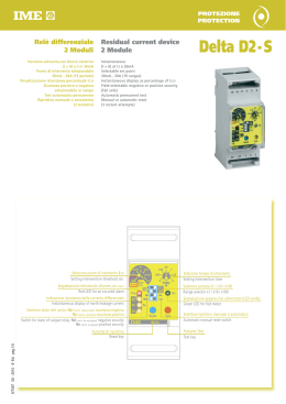
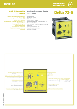
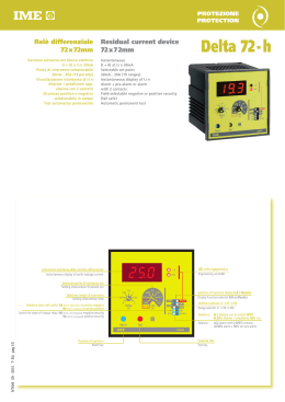
3
DESCRIZIONE FRONTALE
4
Setting intervention threshold IΔn
Predisposizione IΔ n soglia d’intervento
➋ Selettore portata x1 / x10 / x100
IΔn
A
mA
9
Monitor
ELR
10
2
8
~
5
➋ Range selector x1 / x10 / x100
0,03
30mA
30mA
30mA
0,05
50mA
500mA
5A
0,075
75mA
750mA
7,5A
0,1
100mA
1A
10A
7
1
A
mA
0,15
150mA
1,5A
15A
0,2
200mA
2A
20A
0,3
300mA
3A
30A
Con portata impostata 0,03 il selettore di portata (x1/x10/x100) è automaticamente escluso.
Il valore di IΔn impostato è sempre 30mA.
With range set on 0,03 the range selector (x1/x10/x100) is automatically
excluded.
Set IΔn value is always 30mA.
Controllare che il valore d’intervento selezionato sia compatibile con le sensibilità minima rilevabile dal trasformatore toroidale abbinato.
Check that selected intervention value matches the lowest sensibility detectable by the connected ring current transformer.
➌ Indicatore digitale della corrente differenziale istantanea
➍ LED unità ingegneristica
➌ Instantaneous display of earth leakage current
➍ Engineering unit LED
L’accensione del LED indica se il valore visualizzato è espresso in mA oppure A
(t = 0 )
6
x1
x10
x100
10781293
FRONT DESCRIPTION
➎ Pulsante di prova
➎
Permette di simulare la condizione di allarme
➏ Pulsante di ripristino lo stato di allarme permane fino a quando l’operatore non
agisce sul tasto RESET.
Il ripristino è inibito con corrente differenziale persistente: > 60% IΔn impostata
➐ Selettore Al.2 / AL.50%
Al.2 = relè di allarme con doppio contatto (1 SPDT + 1 SPST).
Al.50% = relè di allarme (SPDT) + relè di preallarme (SPST).
Il relè di preallarme è con soglia intervento fissa, pari al 50% del valore di IΔn
selezionato .
Selettore stato relé uscita: Nd (norm. diseccitato) sicurezza negativa Ne (norm. eccitato) sicurezza positiva.
Il relè di preallarme è sempre norm. diseccitato.
Predisposizione ritardo intervento
ATTENZIONE! selezionando la soglia d’intervento nella posizione 0,03 viene
automaticamente escluso il ritardo intervento.
➓ Selettore di funzione display
ELR = protezione differenziale attiva, il display indica la corrente differenziale
istantanea, fino al valore massimo della portata selezionata.
➏
➐
Switching on of the LED shows whether the displayed value is expressed in mA or A
Test key
It allows to simulate alarm condition.
Reset key the alarm stays until the operator doesn’t act on RESET key.
Reset is not possible with persistent residual current: > 60% IΔn.
Selector Al.2 / AL.50%
Al.2 = alarm relay with double contacts (1 SPDT + 1 SPST).
Al.50% = alarm relay (SPDT) + pre-alarm relay (SPST).
Pre-alarm relay with fixed intervention threshold, equal to 50% of selected IΔn
value .
Switch for state of output relay: Nd (normally de-energised) negative security
Ne (normally energised) positive security.
Pre-alarm relay is always normally de-energized.
Setting intervention delay
ATTENTION! to set the intervenction threshold on position 0,03 the intervention delay is automaticall excluded, independently of range selector position.
➓ Display function selector
ELR = differential protection on. The display shows the instantaneous differential current up to the highest value of selected range.
FUNZIONE ELR • ELR FUNCTION
or
Monit
ELR
(t = 0 )
~
0,03...0,3A
0,3...3A
3...30A
CONDIZIONE DI FUNZIONAMENTO • WORKING CONDITION
VISUALIZZAZIONE • DISPLAY
SORVEGLIANZA • MONITORING
VALORE ISTANTANEO CORRENTE DIFFERENZIALE
DIFFERENTIAL CURRENT INSTANTANEOUS VALUE
SUPERAMENTO SOGLIA IΔn • EXCEEDING THE THRESHOLD
PORTATA IMPOSTATA /AL (ALTERNATI) • LOADED RANGE / AL (ALTERNATING)
INTERRUZIONE COLLEGAMENTO TOROIDE - RELE’
TD TRANSFORMER-RELAY CONNECTION BREAKDOWN
CT (LAMPEGGIANTE) • CT (BLINKING)
TEST MANUALE • MANUAL TEST
AL (FISSO) • AL (FIXED)
Monitor = protezione differenziale disattivata, lo strumento funziona unicamente come visualizzatore, nel campo 3mA...50A.
In condizione di allarme (superamento soglia impostata) il display visualizza
alternativamente il messaggio di allarme AL e la portata selezionata.
È possibile visualizzare l’effettivo valore della corrente differenziale istantanea,
passando dalla funzione ELR a quella Monitor.
In questo caso occorre spostare il selettore ➓ in posizione Monitor (sul display
appare la dicitura AL fissa) quindi escludere la protezione differenziale, premendo il tasto RESET.
ATTENZIONE!
In questa condizione l’apparecchio svolge esclusivamente la funzione di visualizzatore.
Per ripristinare la protezione differenziale occorre riportare il selettore ➓ in
posizione ELR.
Monitor = differential protection off. The meter works just as display, in the
range 3mA…50A
In alarm condition (exceeding the loaded threshold), the display alternatively
shows AL alarm message and the selected range.
It is possible to display the real instantaneous differential current value shifting
from ELR to Monitor function.
In this case it is necessary to switch the selector ➓ to Monitor position
(display shows AL caption fixed); then exclude the differential protection by
pressing RESET push-button.
ATTENTION!
In this condition, the meter just works as a display.
To reset the differential protection you must switch the selector ➓ to ELR
position once again.
ISTRUZIONI DI CABLAGGIO
• La posizione di fissaggio risulta completamente indifferente ai fini del funzionamento.
• Le operazioni di predisposizione (soglia intervento, tempo ritardo, ecc.) devono
essere effettuate con apparecchio non alimentato.
• Rispettare scrupolosamente lo schema d'inserzione, una inesattezza nei collegamenti è ineviitabilmente causa di funzionamento anomalo o di danni all'apparecchio.
• L'ottenimento della piena funzionalità del sistema di protezione differenziale è legato alle modalità di installazione, per cui si consiglia:
☞ Ridurre al minimo la distanza tra toroide e relè
☞ Utilizzare cavi schermati o intrecciati per la loro connessione
☞ Evitare di disporre i cavetti di connessione toroide-relè parallelamente a conduttori
di potenza
☞ Evitare di installare toroide e relè in prossimità di sorgenti di campi elettromagnetici intensi (grossi trasformatori).
■
WIRING INSTRUCTIONS
• Mounting position do not affect in any way the proper working.
• Setting operations (intervention threshold, delay time, etc.) must be carried
out with non-fed meter.
• Please carefully follow the wiring diagram; an error in connecting the relay may give
rise to irregular working or damages.
• Four full functional of the earth relay the following installation recommendation
should be adopted.
☞ To reduce as much as possible the distance between ring current transformer
and relay.
☞ To use only shielded or twisted cables for their connection
☞ To avoid in placing ring current transformer-relay connection cables parallelly to
power wires
☞ To avoid in mounting ring current transformer and relay near sources of intense electromagnetic fields (big transformers).
■
ISTRUMENTI MISURE ELETTRICHE SpA
Cod. RD3E2...
ISTRUMENTI MISURE ELETTRICHE SpA
ISTRUMENTI MISURE ELETTRICHE SpA
Via Travaglia 7
20094 CORSICO (MI)
ITALIA
Tel. 02 44 878.1
Fax 02 45 03 448
+39 02 45 86 76 63
www.imeitaly.com
[email protected]
03/ 10
DIMENSIONE DI INGOMBRO • OVERALL DIMENSIONS
D1
D2
D3
X=Y=Z
X
91,6
81,8
L1
L3
L2
Y
N
L1
L3
N
L2
Z
72
68
66x66,3
PE
NUCLEO CHIUSO / CLOSED CORE
68
5,5
74,4
72
78,2
(1)
CODICE
PASSAGGIO CAVO
IΔn min
CODE
PASSING CABLE
TDGA2
NUCLEO APRIBILE / OPEN CORE
A
In
A
Imax
A
Ø 28
0,03
65
TDGB2
Ø 35
0,03
TDGH2
Ø 60
TDGC2
(2)
CODICE
PASSAGGIO CAVO
IΔn min(1)
A
In
A
Imax(2)
A
CODE
PASSING CABLE
390
TDAA2
Ø 110
0,5
250
1500
70
420
TDAB2
Ø 150
0,5
250
1500
0,03
90
540
TDAC2
Ø 300
1
630
3780
Ø 80
0,05
170
1020
TDGD2
Ø 110
0,1
250
1500
TDGE2
Ø 140
0,3
250
1500
TDGF2
Ø 210
0,3
400
2400
(1)
SICUREZZA NEGATIVA • NEGATIVE SECURITY
S 291/109
S 291/108
AUX.SUPPLY
(+) (-)
A1
A2
AL.2
FAULT
RESET TEST
34 31 32 41 44
TRANSFORMER
T1 T2
27 25 26
FAULT
RESET TEST
34 31 32 41 44
TRANSFORMER
Ba
34 31 32 41 44
TRANSFORMER
T1 T2
27 25 26
FAULT
AUX.SUPPLY
(+) (-)
A1
A2
50%
34 31 32 41 44
RESET TEST
TRANSFORMER
T1 T2
27 25 26
TD
34 31 32 41 44
RESET TEST
TRANSFORMER
T1 T2
27 25 26
B A
Bm
TD
L1
L2
L3
N
SICUREZZA POSITIVA • POSITIVE SECURITY
S 291/114
FAULT
AUX.SUPPLY
(+) (-)
A1
A2
50%
34 31 32 41 44
RESET TEST
TRANSFORMER
T1 T2
27 25 26
Ba
B A
AUX.SUPPLY
(+) (-)
A1
A2
B A
L1
L2
L3
N
FAULT
50%
34 31 32 41 44
RESET TEST
TRANSFORMER
T1 T2
27 25 26
B A
Bm
TD
TD
TD
L1
L2
L3
N
FAULT
TD
S 291/115
Ba
L1
L2
L3
N
T1 T2
27 25 26
AUX.SUPPLY
(+) (-)
A1
A2
B A
Al.50%
B A
Bm
34 31 32 41 44
TRANSFORMER
L1
L2
L3
N
S 291/113
S 291/112
RESET TEST
RESET TEST
TD
SICUREZZA NEGATIVA • NEGATIVE SECURITY
50%
FAULT
Ba
B A
L1
L2
L3
N
FAULT
S 291/111
AUX.SUPPLY
(+) (-)
A1
A2
T1 T2
27 25 26
TD
L1
L2
L3
N
AUX.SUPPLY
(+) (-)
A1
A2
SICUREZZA POSITIVA • POSITIVE SECURITY
S 291/110
AUX.SUPPLY
(+) (-)
A1
A2
B A
Bm
Minima corrente IΔn valore minimo di IΔn impostabile sul relè differenziale abbinato al toroide
IΔn lowest current IΔn lowest value that can be set on earth leakage relay connected with toroid
(2)
Corrente di test corrispondente a 6In: Imax (EN 60947-2 annex M)
Test current corresponding to 6In: Imax (EN 60947-2 annex M)
L1
L2
L3
N
Scarica