VALUTAZIONI DI
VULNERABILITÀ PER ANALISI DI
RISCHIO E SCENARI DI DANNO
Mauro Dolce
Direttore Ufficio Rischio Sismico e Post-emergenza,
Presidenza del Consiglio dei Ministri –
Dipartimento Protezione Civile, Roma
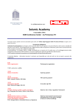
Hazard
Vulnerability
Seismic Risk
Exposure
VULNERABILITY
The Seismic Vulnerability of a construction is
meant as its proneness to be damaged by seismic
actions. It is measured as the damage to the
construction produced by a seismic event of given
intensity.
The Seismic Vulnerability of a construction is a
behavioural characteristic which is described by a
cause – effect law, where the earthquake is the cause
and the damage is the effect (Sandi, 1986)
A deterministic or probabilistic approach can be used:
D = f(q, T)
Æ Damage function
Prob(D = d | q,T) Æ Damage distribution
• VULNERABILITY
DWELLING BUILDINGS
PUBLIC AND STRATEGIC BUILDINGS
MONUMENTAL BUILDINGS
LIFELINES AND INFRASTRUCTURES
• PRIMARY VULNERABILITY:
PHYSICAL DAMAGE
• SECONDARY VULNERABILITY:
CONSEQUENCES OF THE PHYSICAL DAMAGE
(REPAIR COST, USABILITY)
• TOTAL VULNERABILITY
CONVOLUTION OF PRIMARY AND SECONDARY
VULNERABILITIES
INVENTORY: A MAJOR PROBLEM !!!
Very often the main problem in vulnerability and
risk evaluation is the availability of the needed
information for the application of any method,
whose costs and time are consistent with the
scopes of the evaluation.
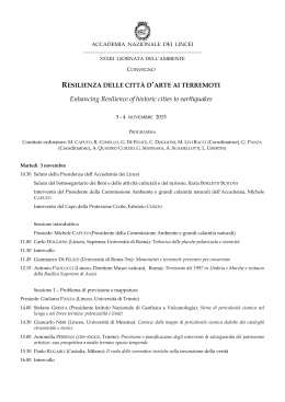
SEISMIC VULNERABILITY OF BUILDINGS
SEISMIC INTENSITY, q
DAMAGE, d
BUILDING, T
LOSS, L
PARAM. OF SOIL MOTION
Mechanical damage
Economical
forza
MACROSEISMIC INT.
Functional
V
VI
VII
VIII
IX
X
XI
XII
Observed damage
d = f(q, T)
L = f(d, T)
I
II
III
IV
V
VI
VII
VIII
IX
X
XI
XII
SEISMIC INTENSITY
Macroseismic intensity
MACROSEISMIC INTENSITY (MCS, EMS, MMI)
FOR HISTORICAL REASONS (CATALOGUE)
SOMETIMES MSK ‘76 OR EMS ‘98 ARE USED TO
EVALUATE THE PRIMARY VULNERABILITY IN
SCENARIO ANALYSES
SOIL MOTION PARAMETERS (PGA,
ARIAS INTENSITY, SPECTRAL
ORDINATES,ACCELEROGRAMS …)
THEY ARE OBTAINED FROM ATTENUATION
RELATIONS, AS FEW RECORDS ARE AVAILABLE AT THE
SITES WHERE A POST-EARTHQUAKE SURVEY WAS
CARRIED OUT.
PHYSICAL DAMAGE
VISUAL DAMAGE
(subjective)
Observed damage on real
damaged buildings
INSTRUMENTAL
Damage measured with
OR CALCULATED
instruments or computed:
DAMAGE
• With experimental tests on
(objective)
models or monitoring systems
in real structures
• With mathematical models
ECONOMIC DAMAGE
The economic damage usually is relevant to the entire
construction and is obtained as the cost for repairing
the damage (visual or mechanical)
It can be expressed as
• unitary repair cost (per square meter)
or as
• (repair cost / contruction cost)
ratio
METHODS FOR VULNERABILITY EVALUATION
A relationship must be established between:
A parameter which represents the soil motion, q
A parameter which represents the damage, d
q
d
Experiments on real structures or models (lab)
Very expensive, useful for single buildings.
Numerical simulation of the seismic behaviour
Needs a deep knowledge of the structure and its materials or extensive
parametric analyses for a probabilistic approach for class of structures
Statistical elaboration of post-earthquake survey data
The damage distribution is obtained via statistical elaborations of post
earthquake survey data, and is referred to classes of buildings
Identification and quantification of vulnerability factors
For each buildings some vulnerability factors are identified and quantified
through a conventional scoring system, then suitably combined to get a
vulnerability index
Expert judgement
Expert judgements are collected for classes of buildings and suitably elaborated
EVALUATION METHODS CAN BE APPLIED TO:
SINGLE BUILDINGS
THE RESULTS ARE USED FOR SINGLE BUILDINGS
OR THEY ARE EXTENDED TO A CLASS OF
BUILDINGS HAVING COMMON CHARACTERISTICS
CLASS OF BUILDINGS
THE RESULTS ARE DRAWN FROM A LARGE SAMPLE
OF BUILDINGS, USUALLY THORUGH A
STATISTICAL APPROACH.
USING:
DETERMINISTIC OR PROBABILISTIC APPROACHES
D=f(q, T)
Prob(D=d|q,T)
In-field or Lab experimental tests
REAL STRUCTURE
Seismic
Action
q
Acceler.
APPARENT AND
MECHANICAL d
DAMAGE
seconds
MEASURES OF:
• deformations
• displacements
• period
Materials (Original or similar)
Structure to be tested
(or reduced scale model)
d = f(q)
WARNING:
AMBIENT VIBRATION TESTS CANNOT PROVIDE DIRECT EVALUATION OF VULNERABILITY
Experimental tests in other fields : crash tests
Advantages
•Controlled actions
•Measurable performances
Drawbacks
•Very expensive
•Applicable only to single
cases (OK for standard
products)
Numerical simulation of the seismic
behaviour of a structure
REAL BUILDING
SEISMIC
ACTION
sisma
secondi
q
MECHANICAL
DAMAGE
ADINA
DEFORMED XVMIN -10.39
XVMIN 7.071
-10.39
ADINA
DEFORMEDXVMAX
LOAD_STEP
XVMAX-1.429
7.071
LOAD_STEP
YVMIN
TIME
13.99 1.526
YVMIN21.84
-1.429
TIME 13.99 1.526
YVMAX
YVMAX 21.84
Z
X
Y
Z
X
Y
CLOSED
CLOSED
CRACKS
CRACKS
MATERIAL CONST. LAWS
d
• Drift
• Plastic
Rotations
• Ductility
• Period
carico
deformazione
MATHEMATICAL MODEL
d = f(q)
Statistical analysis of observed damage
q
d
Buildings are
grouped in
behavioural
classes, T
The damage is described in a scale
of discrete damage levels: d=0,.., n
The seismic input is described by the macroseismic
intensity or by soil motion parameters, q
For each vulnerability class the statistical damage
distribution DPM(d/q/T) is found for each available
intensity and fitted with a probabilistic distribution
-
-
GLOBAL
damage levels
in masonry
buildings:
classification
according to
EMS ‘98
GLOBAL
damage levels
in R/C
buildings:
classification
according to
EMS ‘98
AEDES FORM – Damage survey section
1/3 - 2/3
< 1/3
> 2/3
1/3 - 2/3
< 1/3
C
D
E
F
G
H
I
L
Nullo
> 2/3
B
5 Danno preesistente
< 1/3
4 Tamponature-tramezzi
A
3 Copertura
1/3 - 2/3
2 Solai
D0-D1
Leggero
1 Strutture verticali
D2-D3
Medio grave
> 2/3
Tipo
struttura
D4-D5
Gravissim o
(1)
Livello
Rilievo del
danno
DANNO
DAMAGE TO SINGLE COMPONENTS
DAMAGE LEVELS AND EXTENSION ARE DIFFERENT IN
THE VARIOUS POST-EVENT SURVEYS AFTER THE 1980
EARTHQUAKE
DAMAGE LEVEL
0=NO DAMAGE, 8=COLLAPSE
0=NO DAMAGE, 5=COLLAPSE
3 LEVELS, + D=0
4 LEVELS
DAMAGE EXTENTION
NOT CONSIDERED
MOST EXTENDED
1/3-1/2-2/3
1/3-1/2-2/3
IRPINIA ‘80
ABRUZZO ‘84
UMBRIA-MARCHE ‘97
POLLINO ’98,
MOLISE ‘02
IRPINIA ‘80
ABRUZZO ‘84
UMBRIA-MARCHE ‘97
POLLINO ‘98
IN RELATION TO THE KIND OF LOSS TO BE ANALYSED
AS A CONSEQUENCE OF THE PHYSICAL DAMAGE,
DIFFERENT MEASURES OF DAMAGE SHOULD BE
CONSIDERED
USABILITY
COST OF REPAIR
NO REPAIR POSSIBILITY
D=MAX(Dmax,i)
D=∑(αiDmean,i)
D=MAX(Dmean,i)
Dmax,i= Max damage level of the component
Dmean,i= Average damage level of the component
Αi = Economic weigth of the component
i=1, Number of components
VECTORIAL definition of the physical damage?
Risk and scenario analyses would become too complicate in
relation with the uncertainty of seismic events.
Vulnerability classes
MSK ‘76
A – Rubble masonry, Adobe (low quality masonry)
B – Ordinary masonry, masonry with wood frames
embedded, squared stone masonry (Mediium quality)
C – High quality masonry (C1), Reinforced concrete
(C2) (frame, walls, dual systems)
z
z
−
EMS ‘98
classes D, E, F are introduced to consider
different behaviours of reinforced concrete and
reinforced masony, as well as of antiseismic
structures.
Vulnerability classes of masonry and R/C buildings
from the description of vertical and horizontal
structural components (Irpinia, 1980; 38.000
edifici) according to Braga et al., 1982
MASONRY
Vertical Rubble
stones
Horiz.
Vaults
A
Wood
A
Steel
B
R/C
B
squared
stones
A
A
B
C1
bricks
A
C1
C1
C1
R/C
C2
Probabilistic Damage Distribution (DPM)
IRPINIA 80
Parametric and non parametric distributions were
drawn from the 1980 eq data
A(o), B(*), C
0.5
0.8
0.4
Frequency
Frequency
A(o), B(*), C1(+), C2(x)
1
0.6
0.4
0.2
0.1
0.2
0
0
0.3
1
2
3
Damage level
4
5
I=V MCS, Classes A, B, C1, C2
0
0
1
2
Damag
I=IX-X MCS, Classes A, B, C1, C2
Normalised mean damage to vertical structures
as a function of the macroseismic intensity
(MCS) from Irpinia ’80 data
0,70
Classe A
Classe B
Classe C
Danno str_vert
0,60
0,50
0,40
0,30
0,20
0,10
0,00
V
VI
VII
VIII
IX
I (MCS)
d=0 no damage,
d=1 collapsed building
X
Organisation
Vulnerability index
(Benedetti – Petrini model / GNDT L.2)
Vulnerability is conditioned
by some factors (resisting
system, global resistance,
degradation, etc.).
Quality
Resistance
R1
Sisma
Iv
R2
R3
Resistenza R = ∑ Ri
Position
Slabs
Shape
Wall distance
Roof
Non-structural elem.
Vulnerability index
IV = ∑wi pi
i =1,.., N N=Number of factors
wi =score of the i-th factor
pi =weight of the i-th factor
Weight is related to the
influence of the factor on the
seismic global behaviour of
the structural type.
Score is related to the quality
assigned to the factor in the
specific case.
The vulnerability index
does not provide any
evaluation of expected
damage for a given level
of the seismic shaking
A correlation must be
found between:
z Vulnerability index (→ Iv)
z Damage level d
z Intensity of the
earthquake a
(seismic vulnerability)
d=g(a,ai,ac) & ai,ac=f(Iv)
ai Accelerazione di inizio danno
ai = f ( I v ) = α i exp ( − β i I v )
ac Accelerazione di il collasso
Legge deterministica trilineare
accelerazione - danno
d
1
0,9
Iv = 100
0,8
0,7
Iv = 60
0,6
0,5
Iv = 20
0,4
ac = f ( I v ) = (α c + β c V γ ) −1
0,3
Indice di vulnerabilità Iv
0,2
20
60
100
0,1
0
0
ai
0,1
0,2
ac
0,3
0,4
d=g[a,f(Iv)]
0,5
Fragility curves
0,6
a
⎧0
⎪
d = ⎨(a − ai ) (ac − ai )
⎪⎩1
a < ai
ai < a < ac
a > ac
GNDT-SAVE: Evolution of the model
based on vulnerability factors for
masonry buildings
Based on a mechanical model of the PGA
corresponding to the structural collapse
Æ Overcomes the procedure leading to the
vulnerability index
INPUT: data from II lev. GNDT inspection form
Vulnerability model for masonry buildings based on GNDT II
level approach
Identification of
the prevailing
collapse
mechanism
Re-evaluation of
the Ccoefficient
(conventional
resistance)
Modification of
the
C-coefficient
Basata
Basatasui
suiparametri
parametrididivulnerabilità
vulnerabilitàdidiIIIIlivello
livelloGNDT,
GNDT,inin
relazione
all’attribuzione
ad
una
delle
4
classi
:
A,
relazione all’attribuzione ad una delle 4 classi : A,B,
B,CCeeDD
••Parametro
Parametro1:1:Tipo
Tipoed
edorganizzazione
organizzazionedel
delsistema
sistemaresistente
resistente
••Parametro
5:
Orizzontamenti
Parametro 5: Orizzontamenti
••Parametro
Parametro9:9:Copertura
Copertura
IlIlcoefficiente
coefficienteCC(Parametro
(Parametro3),
3),èèililrapporto
rapportotra
trala
laresistenza
resistenza
ultima
ultimaaataglio
taglioal
alpiano
pianoed
edililpeso
pesodell’edificio
dell’edificiosovrastante.
sovrastante.
IlIlcoefficiente
coefficienteCCviene
vienerivalutato
rivalutatoassumendo
assumendovalori
valorididiresistenza
resistenza
specifica
a
taglio
della
muratura
(
τ
)
non
convenzionali
k ) non convenzionalima
specifica a taglio della muratura (τ
mapiù
più
k
realisticamente
realisticamenteprossimi
prossimiaaquelli
quellididirottura
rotturadel
delmateriale.
materiale.
Basata
Basatasu
sualcuni
alcuniaspetti
aspettididivulnerabilità
vulnerabilitàdesumibili
desumibilidalle
dalleschede
schede
GNDT
GNDTattraverso
attraversola
ladefinizione
definizionedidi44coefficienti
coefficienticorrettivi:
correttivi:
•K6
•K6ÅÅregolarità
regolaritàininpianta
piantadell’edificio
dell’edificio(Parametro
(Parametro6)
6)
•K7:
Å
regolarità
in
elevazione
dell’edificio
(Parametro
•K7: Å regolarità in elevazione dell’edificio (Parametro7)
7)
•K8:
Å
distanza
massima
tra
le
murature
(Parametro
8)
•K8: Å distanza massima tra le murature (Parametro 8)
•Kh:
•Kh:ÅÅaltezza
altezzadidiinterpiano
interpianoeenumero
numerodidipiani.
piani.
PGA =C ⋅
Transformation
of C into PGA
q
PMod ⋅ η ⋅ ASpett ⋅ S
η è il fattore di smorzamento
η è il fattore di smorzamento
qq==1.5
è il coefficiente di duttilità
1.5 è il coefficiente di duttilità
PMod
PModèèililcoefficiente
coefficientedidipartecipazione
partecipazionemodale
modale
S è il fattore che tiene conto del tipo di suolo
S è il fattore che tiene conto del tipo di suolo
ASpett
ASpettèèililcoefficiente
coefficientedidiamplificazione
amplificazionespettrale
spettrale
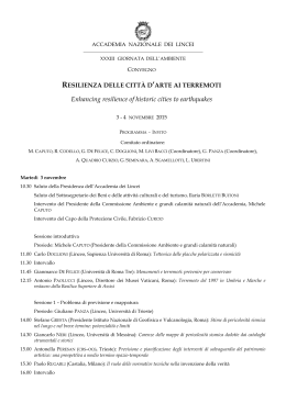
Identification of the collapse mechanism
Based on the scoring (A,B,C,D) of the three factors 1,5,9 one of the three
meccanisms of collapse is identified:
Mech. 1 = prevailingly flexural
Mech. 2 = prevailingly shear
Mech. 3 = hybrid shear-fexural
MECCANISMO
1
2
3
1-1
1-2
1-3
1-4
1-5
1-6
2-1
2-2
2-3
2-4
3-1
3-2
3-3
PARAM 1
A B C D
PARAM 5
A B C D
PARAM 9
A B C D
DESCRIZIONE
PREVALENTEMENTE
FLEXURAL
FLESSIONALE
PREVALENTEMENTE
SHEAR
TAGLIANTE
MISTO
TAGLIANTE
HYBRID
FLESSIONALE
>0.99
0.95 - 0.99
2000
0.90 - 0.94
0.85 - 0.89
0.80 - 0.84
0.75 - 0.79
0.70 - 0.74
0.65 - 0.69
0.60 - 0.64
0.55 - 0.59
1500
0.50 - 0.54
0.45 - 0.49
0.40 - 0.44
0.35 - 0.39
0.30 - 0.34
0.25 - 0.29
0.20 - 0.24
0.15 - 0.19
0.10 - 0.14
0.05 - 0.09
0.00 - 0.04
PGA collapse of buildings with different collapse
mechanisms
2500
TUTTI
MEC 2
MEC 1 E 3
Distribution
Distributionof
ofthe
the
collapse
collapsePGA
PGA
1000
500
0
RISK
RISKMAPS
MAPS
Mechanical Method for
R/C buildings
Manfredi et al.
The definition of class is based on the parameters that
affect the response of the building, which are available at
a large scale:
• Plan shape
• Height (Number of stories)
• Age (Construction regulations)
Definition of the geometry of
models pertaining to a given
class of buildings
Design of structural
members based on the
regulations of the time of
construction
The seismic capacity is obtained from a series of static non
linear analyses (pushover) while varying the geometrical and
mechanical characteristics of the model
The demand is obtained from pseudo- acceleration elastic
spectra derived from hazard analyses
The comparison between demand and capacity provides
the performance point
The probability of attaining a given limit state is obtained by
suitably accounting for uncertainties
Displacement Based
Method for R/C buildings
Pinho et al.
Evaluation of the deformation capacity from the deformation
capacities of the single components (beams and columns)
and of the considered failure mechanism.
Ad esempio per la deformazione allo snervamento di una
struttura in ca, con meccanismo di danno per
plasticizzazione delle colonne, si ottiene
Da ipotesi sulla deformazione
delle colonne
Da analisi numeriche
su strutture in ca
Δsy=f(Ty)
In maniera similare si ottiene lo spostamento in
corrispondenza di un determinato stato limite
Lo stato limite è individuato dai valori
di deformazione unitaria del cls o
dell’acciaio
The demad is provided by displacement elastic spectra for different
values of damping, as a function of the limit state considered.
Given the period of the structure the corresponding point on the demand
spectrum is obtained and the attainment of a given limit state is
evaluated.
The probability of attaining a given limit state is obtained by
suitably accounting for uncertainties
VC – VM
Mechanical method for R/C
and Masonry buildings
(GNDT-SAVE)
• Quantitative evaluation of seismic vulnerability with respect to
the conditions of:
• Operability
• Collapse
• These methods utilise simplified calculation methods, which need
a non detailed description, and operate on single stories, and the
q-factor to account for ductility
• For R/C structures they account for possible positive and
negative contributions of the non-structural elements (infill walls)
VC – Vulnerability of R/C
COLLAPSE MECHANISMS
In the frame of existing buildings it is quite probable that a strong beam
– weak column mechanism takes place in which:
• The anelastic deformations are concentrated at the end of the
columns
• The low percentage of the longitudinal reinforcement do not
produce a shear non-ductile failure of the elemtn before ductile
flexural yielding
VM – Vulnerability of Masonry
COLLAPSE MECHANISMS
• Failures and overturning for out-of-plane actions, i.e. normal to the
wall.
They are usuallly more dangerous and occur for low seismic
intensities, when the links are inadequate and/or when the slabs are
too flexible in their plane.
• Failures, mailny due to shear, for in-plane actions, i.e. parallel to the
wall.
Public buildings are often characterised by good connections between
orthogonal walls, good connections between walls and slabs, as well as
by in-plane stiff slabs
VC – VM
DUCTILITY COEFFICIENT
⎛
Vpil,i , j ⎞
⎟ ⋅ (p1, j ⋅ p 2 ⋅ p 3 ) ≥ 1
α DUT , j = ∑ ⎜ α DUT ,pil,i , j ⋅
⎜
Vj ⎟⎠
i ⎝
αDUT, pil i, j = 1
• Shear non-ductile failure of columns
• Reduced ductility of columns due to compression for vertical
loads
αDUT, pil i, j = 3 ⋅ (0.2 + (1 - σc/fc)1.2 / 1.11) ≤ 3
• Irregularity of strength in elevation (rid.0.8-1)
• Soft story (reduction 0.7)
} MINIMUM
• In plan stiffnes and mass irregularity (reduction 0.9-1)
• Shape irregularity (reduction 0.9-1)
1 ≤ αDUT ≤ 3
in the analyses without infills (in R/C buildings)
1 ≤ αDUT ≤ 1.5
in the analyses without infills (in R/C buildings)
VC
VALIDATION
Comparisons have been made with:
• Experimental tests on large scale models (from 1:2.5 to
1:4) (shaking table and Pseusodynamic)
• Non linear dynamic analysis on 2D models
• Japanese method for vulnerability assessment
VC
VALIDATION
Æ SUMMARY OF THE EXPERIMENTAL RESULTS
Risultati VC
T
MANSIDE (1:3.3)
MANSIDE tamp (1:3.3)
ECOEST II (1:4)
POP (1:2.5)
0.307
0.141
0.433
0.554
Risultati Sperimentali
PGA/g piano
0.345
0.691
0.512
0.347
1°
1°
3°
3°
T
PGA/g
piano
0.294
0.136
0.433
0.59
0.28 - 0.48
0.63 - 0.91
>0.332
> 0.35
1°
1°
3°
3°
SEISMIC VULNERABILITY
OF MONUMENTAL BUILDINGS
Vulnerability of cultural heritage
(Lagomarsino et al.)
3 LEVELS
For a progressive deepening and a greater detail of the available data
Data Origin
Knowledge achieved
Level 0
List of Monuments (LSUParchi, Ministry of Fine
Arts)
Level I
More detailed available data
Typological Identification and
base
Behaviour Modifier Recognition
Quick field survey
Level II Detailed field survey
Typological Identification
Typological Identification, rough
geometrical survey, vulnerability
indicators and a-seismic devices
DISEG - Università degli Studi di Genova - Genova
2 APPROACHES
Macroseismic
Approach
Mechanical
Approach
Seismic
Input
Macroseismic Intensity
ADRS
Level 0
Typological Vulnerability Index
Typological Capacity Curve
Level I
Vulnerability Index
Capacity Curve
Level II
Vulnerability Index from a
Macroelement Analysis
Capacity Curve of a
Macroelement
DISEG - Università degli Studi di Genova - Genova
LEVEL - 2
Macroseismic Approach
• It is referred to the single macroelements and not to the construction as a whole
• the vulnerability is analysed taking into consideration the collapse mechanisms,
recognized after the systematic observation of the damages of the past
earthquakes.
THE MOLISE EARTHQUAKES
The seismic event, that has shocked the Molise region in the October-November 2002, has
determined a direct engagement of the UR to support the activities coordinated by the Civil
Protection Department (Larino COM - Function 9).
DEVELOPMENT OF A NEW FORM, DERIVED FROM THE UMBRIA-MARCHE ONE
The observation of the damage has highlighted how the vulnerability directly influences
the activation of the collapse mechanisms. Therefore the survey has been carried out by
considering two complementary aspects: a-seismic devices, vulnerability indicators.
DISEG - Università degli Studi di Genova - Genova
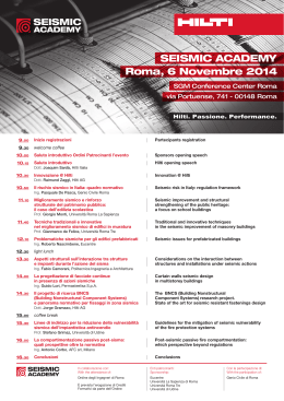
Damage mechanisms
Part of the church
1 OVERTURNING OF THE FACADE
2 DAMAGE AT THE TOP OF FACADE
28 DAMAGE MECHANISMS
3 SHEAR MECHANISMS IN THE FACADE
4 NARTEX
5 TRANSVERSAL VIBRATION OF THE NAVE
6 SHEAR MECHANISMS IN THE SIDE WALLS
7 LONGITUDINAL RESPONSE OF THE COLONNATE
8 VAULTS OF THE NAVE
FACADE
NAVE
9 VAULTS OF THE AISLES
10 OVERTURNING OF THE TRANSEPT’S END WALL
11 SHEAR MECHANISMS IN THE WALLS TRANSSEPT
12 VAULTS OF THE TRANSEPT
13 THIUMPHAL ARCHES
14 DOME AND DRUM
15 LANTERN
16 OVERTURNIG OF APSE
17 SHEAR MECHANISMS IN PRESBITERY AND APSE
18 VAULTS IN PRESBITERY AND APSE
19 PART OF ROOF: SIDE WALLS OF NAVE AND AISLES
20 PART OF ROOF: TRANSEPT
21 PART OF ROOF: APSE AND PRESBITERY
22 OVERTURNING OF THE CHAPELS
23 SHEAR MECHANISMSIN THE WALLS OF CHAPELS
24 VAULTS OF CHAPELS
TRANSEPT
THIUMPHAL ARCHES
DOME
APSE
COVERING
CHAPEL ADJACENT
BUILDINGS
25 INTERACTIONS NEXT TO IRREGULARITIES
26 PROJECTIONS (DOMED VAULTS, SPIRES, PINNACLES, STATUES)
27 BELL TOWER
28 BELL CELL
PROJECTIONS/
BELL TOWER
Overturning of the facade
Shear
mechanisms
in the
facade
Transversal
mechanisms
of the
nave
Damage at the top of the facade
Nartex
LEVEL - 2
Mechanical Approach
• It is referred to the single macroelements and not to the construction as a whole
•ACapacity
arekinematism
evaluated for is
anthe
hypothesised
collapse mechanism of a single
typical curves
collapse
Façade Overturning
macroelement
(OUT-OF-PLANE MECHANISM - I mode)
A typical collapse kinematism for churches is the Façade Overturning
OUT-OF-PLANE MECHANISM - I mode
h
λm g
mg
s
• Mechanical approach based on the hypothesis of
rigid body and zero tensile strength of masonry;
• Loss of static equilibrium (l=s/h);
• Complete overturning of the façade (dynamic action)
when displacement Sd is equal to s/2;
Some factors may modify the structural response of
the façade: connection with side-walls or the presence
of tie-rods
SECONDARY VULNERABILITY
OF DWELLING BUILDINGS
SEISMIC VULNERABILITY OF BUILDINGS
SEISMIC INTENSITY, q
DAMAGE, d
BUILDING, T
LOSS, L
PARAM OF SOIL MOTION
Mechanical damage
Economical
forza
MACROSEISMIC INT.
Functional
V
VI
VII
VIII
IX
X
XI
XII
Observed damage
d = f(q, T)
L = f(d, T)
From visual damage to cost of repair
1
SSN
Damage Factor
0,9
0,8
ATC13(streched)
0,7
Tiedemann
0,6
GNDT
0,5
0,4
0,3
0,2
0,1
0
0
1
2
3
4
5
Dam age level
Mean value of the relative cost of
repair vs. visual damage to vertical
structures
How damage-cost relationships can be calibrated?
1. After a reconstruction activity, making use of
design plans and cost computation. In this case
the cost contribution is correlated to the damage
and vulnerability of the building. Contributions for
repair and seismic strengthening.
2. With purposely made models which, based on
pre-established strategies, provide the repair
cost as a function of the damage and the type of
each component of the building.
Vulnerabilità funzionale
Inagibilità degli edifici residenziali
AGIBILE
PARZIALMENTE
AGIBILE
INAGIBILE
100
Mur. A
Mur. B
Mur. C
C.a.
80
60
40
0
1
2
3
4
5
20
0
Mur. A
Mur. B
Mur. C
C.a.
60
40
20
0
0
1
dmv
Danno medio alle
strutture verticali
E=0.94
100
80
Mur. A
Mur. B
Mur. C
C.a.
%
100
80
60
40
20
0
%
%
Influenza della misura del danno adottata
2
3
4
0
5
1
2
3
4
dm
dMv
Danno massimo alle
strutture verticali
E=0.86
Danno medio all’edificio
E=0.90
E=1-{∑ T [f02 +(1-f5) 2] 0.5T }/N T
Tabella XI. Frequenza relativa di inagibilità (%)
dMv
d A B
C C.a.
N
A
B
0 10 4
2
1
13798 21
7
1 10 4
2
2
9390 15
7
2 30 22 13
11
7766 50 41
3 65 52 40
33
3254 82 75
4 88 84 74
39
2905 96 93
5 96 93 100 100 2135 71 86
dmv
C C.a.
3
1
3
2
27
23
64
38
83
20
100 100
N
5832
23396
4081
3745
2133
61
A
21
16
66
88
97
79
B
7
9
57
89
95
100
dm
C
3
4
47
72
86
100
C.a.
0
2
26
20
83
100
N
3700
26779
4746
2356
1648
19
5
EAEE-TG3 - QUESTIONNAIRE
1) TYPE OF STRUCTURE for which the procedure has
been implemented:
a, b) Reinforced concrete or Masonry buildings; c) Industrial
prefabricated buildings; d) Churches; e) Bridges;
2) TYPE OF APPROACH for vulnerability assessment:
a) Type recognition and classification; b) Scoring of
structural characteristics; c) Mechanical approach;
3) CONSIDERATION OF NON STRUCTURAL ELEMENTS
(NSE)
a) Vulnerability and damage of NSE; b) Positive
collaboration effects ; c) Negative collaboration effects ;
EAEE-TG3 - QUESTIONNAIRE
4) SOURCE OF INFORMATION
a) cadastral or census inventory; b) aerial photos; c) satellite
photos; d) external sight inspection; e) internal sight
inspection; f) architectural drawings; g) structural design
drawings; h) structural design reports; i) rough
geometrical survey; j) detailed geometrical survey;
5) EVALUATION OF MECHANICAL CHARACTERISTICS
OF STRUCTURAL MATERIALS
a) Original design specification; b) Original material test
certificates; c) Typical average values ; d) in situ ND
material testing; e) destructive tests; f) Structural
identification -ambient; g) Structural identification -forced;
6) TYPE OF SEISMIC INPUT: Type of intensity measure
a) Macroseismic intensity ; b) Instrumental intensity;
EAEE-TG3 - QUESTIONNAIRE
7) HAZARD ASSIGNMENT - accuracy or territorial scale
in the evaluation of the basic hazard (excluding site
effects) for the risk assessment.
a) Evaluation at national level; b) Evaluation at regional level;
c) Evaluation at local level;
8) LOCAL AMPLIFICATION EFFECTS
a) Microzonation ; b) Local investigation;
9) TOTAL NUMBER OF STRUCTURES to which the model
has been applied
a) single structures (1-10); ... f) 10001 - 100000; g) > 100000;
EAEE-TG3 - QUESTIONNAIRE
10) TYPE OF USE OF THE STRUCTURES to which the
procedure has been applied
a) Dwelling buildings ; b) Schools; c) Hospitals; d) Other
public buildings; e) Highway bridges; f) Road bridges; g)
Railway bridges; h) Private industry plants; i) Public
industry plants;
11) APPROXIMATE COST (per m2 or m3)
a) < 0.10 €/ m3 (buildings); …. h) > 8.00 €/ m3 (buildings); i)
< 0.10 €/ m2 (bridges); …. n) > 8.00 €/ m2 (bridges);
12) APPROXIMATE MAN HOURS needed per medium size
structure
a) < 10 minutes; ….. f) > 800 h;
13) OUTPUT OF THE PROCEDURE
a) Seismic Vulnerability; b) Seismic Risk - damage;
FINAL REMARKS
Factors to decide type of vulnerability evaluation procedure
and inventory:
•
•
•
•
•
•
PURPOSE AND SCALE of risk assessment or damage
scenario;
ACCURACY AND TYPE OF HAZARD PARAMETERS or
earthquake shaking scenario on which damage scenario
will be based;
AVAILABLE FUNDS to make building inventory vs. costs
of inventory procedures;
AVAILABLE TIME to make building inventory vs. time
needed by inventory procedures;
ACCURACY AND INFORMATION required by vulnerability
approaches;
INFORMATION ALREADY AVAILABLE or easily obtainable
through bibliographic search, interviews, etc.
FINAL REMARKS
•
•
THE ENTIRE PROCEDURE MUST BE CUSTOMIZED AND
OPTIMIZED FOR EACH SPECIFIC SITUATION, taking into
account and balancing the above listed factors, in order to
exploit all the available information, reducing costs and
time while maximizing accuracy.
VULNERABILITY ASSESSMENT AND INVENTORY
PROCEDURES MUST BE ADAPTED RECIPROCALLY,
balancing them with the accuracy of hazard assessment,
to get the desired result.
Scarica