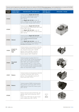
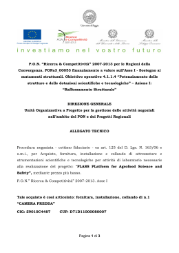
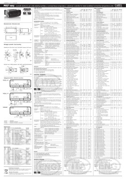
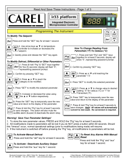
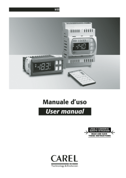
+0500080IE - rel. 1.0 - 18.02.2014 PBB2* - easy blast chiller - regolatore elettronico per abbattitori rapidi / electronic controller for blast chillers Segnalazioni sul display / Signals on the display Icon Function NO POWER & SIGNAL CABLES TOGETHER READ CAREFULLY IN THE TEXT! Montaggio a pannello / Panel mounting 3 29.2 165 3 drilling template dima di foratura 138.4 165 Fig. 1 182 soft 43 chill chill soft freeze hard aux prg mute new freeze hard Startup Normale funzionamento ON OFF Lampeggiante compressore compressore compressore acceso spento richiesto ventilatore acceso ventilatore spento ventilatore richiesto sbrinamento in sbrinamento non sbrinamento atto progress richiesto richiesto uscita ausiliaria uscita ausiliaria attiva funzione AUX attiva AUX non attiva anti-sweat heater Allarme allarme esterno nessun allarme allarmi e malfunAlarm ritardato (prima presente zionamenti dello scadere del tempo ‘A7’) Orologio ON se RTC è impostato non è presente allarme orologio Clock presente almento uno alcuno sbrinaON if RTC sbrinamento tem- mento tempopresent porizzato rizzato Luce uscita ausiliaria uscita ausiliaria attiva funzione Light LUCE attiva LUCE non attiva anti-sweat heater Assistenza nessun malfun- malfunzionaService zionamento mento (es. errore EEPROM o sonde guaste) HACCP funzione non funziona abilitata allarme HACCP abilitata (HA e/o HF) memorizzato Ciclo di abbattiCiclo di abbatti- Conservazione mento in corso mento in corso in corso Blast chilling cycle in progress Compressore Compressor Ventilatore Fan Sbrinamento Defrost AUX ON compressor ON fan ON Normal operation OFF Blinking compressor OFF compressor required fan OFF fan required defrost in progress auxiliary output AUX active delayed external alarm (before the expiry of the time ‘A7’) at least one timed defrost has been set defrost no required auxiliary output AUX not active no alarm present defrost required auxiliary output LIGHT active auxiliary output anti-sweat heater LIGHT not active function active no malfunctions malfunction (es. EEPROM error or probe fault) function not enalbled Blast chilling cycle in progress function enabled HACCP alarm (HA and/or HF) enabled Conservation in progress anti-sweat heater function active alarms and malfunctions no timed defrost clock alarm is present start Descrizione: easy Blast Chiller (PBB2*) rappresenta un’ estensione della gamma di regolatori elettronici easy wide, con funzioni dedicate all’abbattimento rapido della temperatura. Caratteristiche tecniche 140 Fig. 2 28 Dimensioni e connessioni opzionali easy small wide (mm) / Dimensions and optional connections easy small wide (mm) IROPZDSP00: Opzione interfaccia display Display interface option 44 47.5 IROPZKEY**: IROPZ48500: Interfaccia scheda seriale RS485 Chiave di programmazione Programming key Serial board interface RS485 10 Fig. 3 28 Dimensioni e connessioni opzionali easy wide (mm) / Dimensions and optional connections easy wide (mm) IROPZKEY**: Chiave di programmazione Programming key 69 73 IROPZ485S0: Interfaccia scheda seriale RS485 intelligente Smart serial board interface RS485 IROPZDSP00: Opzione interfaccia display Display interface option 10 Fig. 4 Tabella allarmi e segnalazioni: display, buzzer e relè / Table of alarms and signals: display, buzzer azd relay Code ‘rE’ ‘E0’ ‘E1’ ‘E2’-3-4 ‘___’ ‘LO’ ‘HI’ ‘AFr’ ‘IA’ ‘dA’ ‘dEF’ ‘Ed1’-2 ‘Pd’ ‘LP’ ‘AtS’ ‘cht’ ‘CHT’ ‘dor’ ‘Etc’ ‘EE’ ‘EF’ ‘HA’ ‘HF’ ‘dFb’ ‘dFE’ ‘On’ ‘OFF’ ‘rES’ ot End tHI Icon on the display + flashing + flashing + flashing + flashing nessuna flashing flashing flashing flashing flashing acceso nessuna + + flashing flashing + flashing nessuna + flashing + flashing flashing + flashing + flashing flashing flashing segnalazione segnalazione segnalazione segnalazione segnalazione flashing flashing Alarm Buzzer Reset relay ON ON automatic Descrizione Description sonda virtuale di regolazione guasta virtual control probe fault OFF OFF automatic sonda ambiente S1 guasta room probe S1 fault OFF OFF automatic sonda sbrinamento S2 guasta defrost probe S2 fault OFF OFF automatic sonda S3-4 guasta probe S3-4 fault OFF ON OFF ON automatic automatic sonda non abilitata allarme bassa temperatura probe not enabled low temperature alarm ON ON automatic allarme alta temperatura high temperature alarm ON ON manual allarme antigelo antifreeze alarm ON ON automatic allarme immediato da contatto esterno immediate alarm from external contact ON ON automatico / auto- allarme ritardato da contatto esterno matic automatic sbrinamento in esecuzione automatic/manual sbrinamento su evaporatore 1-2 terminato per timeout automatic/manual allarme tempo massimo di pump-down delayed alarm from external contact OFF OFF OFF OFF ON ON defrost running defrost on evaporator 1-2 ended by timeout maximum time pump-down alarm Tensione Potenza 230 V~ (+10...-15%), 50/60 Hz 3 VA, 25 mA~ max. 230 V~ (+10...-10%), 50/60 Hz (vers. 16 A, 8 A, 8 A) PBEVxxAxxxx 115 V~ (+10...-15%), 50/60 Hz / 115 V~ (+10...-10%), 50/60 Hz (ver. 16 A, 8 A, 8 A) 3 VA, 50 mA~ max. PBEVxxHxxxx 115...230 V~ (switching) (+10...-15%), 50/60 Hz 6 VA, 50 mA~ max. 12 V~ (+10...-15%), 50/60 Hz 3 VA, 300 mA~ /mAdc max. PBEVxx0xxxx 12 Vdc, 12...18 Vdc Utilizzare esclusivamente alim. tipo SELV Isolamento isolamento rispetto alla bassissima rinforzato, 6 mm in aria, 8 superficiali, 3750 V isolamento PBEVxxExxxx / PBEVxxxAxxxx / garantito tensione isolamento rispetto alle uscite relè principale 3 mm in aria, 4 superficiali, 1250 V isolamento dall’alimen- PBEVxxHxxxx isolamento rispetto alla bassissima da garantire esternam. con trasformatore di sicurezza (SELV) tazione PBEVxx0xxxx tensione isolamento rispetto alle uscite relè principale, 3 mm in aria, 4 superficiali, 1250 V isolamento Ingressi S1 (sonda 1) NTC o PTC a seconda del modello / NTC or PTC according to the model S2 (sonda 2) NTC o PTC a seconda del modello / NTC or PTC according to the model DI1/ S3 (sonda 3) contatto pulito, resistenza contatto < 10 Ω, corrente di chiusura 6 mA / NTC o PTC a seconda del modello DI2 / S4 (sonda 4) contatto pulito, resistenza contatto < 10 Ω, corrente di chiusura 6 mA / NTC o PTC a seconda del modello Distanza massima sonde ed ingressi digitali minore di 10 m. Nota: nell’installazione tenere separati i collegamenti di alimentazione e dei carichi dai cavi delle sonde, ingressi digitali, display ripetitore e supervisore. Tipo sonda NTC std. CAREL 10 kΩ a 25 °C, range –50T90 °C errore di misura: 1 °C nel range –50T50 °C / 3 °C nel range 50T90 °C NTC alta temperature 50 kΩ a 25 °C, range –40T150 °C errore di mis.: 1,5 °C nel range –20T115 °C / 4 °C nel range ester. a –20T115 °C PTC std. CAREL (mod. specifico) 985 Ω a 25 °C, range –50T150 °C errore di misura: 2 °C nel range –50T50 °C / 4 °C nel range 50T150 °C Uscite relè EN60730-1 UL873 (a seconda modello relè 250 V~ cicli manovra 250 V~ cicli manovra del mod.) PBEVxx(E,A)(P,S,V,Y)xxx 5 A (*) 5(1) A 100000 5 A res. 1 FLA / 6 LRA 30000 C300 PBEVxx(E,A)(N,C,A,L)xxx 8 A (*) 8(4)A N.O. 6(4)A N.C. 100000 8 A res. 2 FLA 30000 PBEVxx(0,H)(N,C,A,L)xxx 2(2)A N.O./N.C. 12 LRA C300 PBEVxx(E,A)(P,S,V,Y)xxx 16 A (*) 10(4)A N.O. (fino a 60°C) 100000 12 A res. 5 FLA 30000 PBEVxx(0,H)(N,C,A,L)xxx 12 (2) A N.O./N.C. 30 LRA C300 2 Hp 10(10)A 100000 12 A res. 12 FLA 72 LRA 30000 isolamento rispetto alla bassissima tensione rinforzato, 6 mm in aria, 8 superficiali, 3750 V isolamento isolamento tra le uscite relè indipendenti principale, 3 mm in aria, 4 superficiali, 1250 V isolamento Connessioni sezione cavi da 0,5 - 2,5 mq corrente max 12 A (*): Relè non adatti per carichi fluorescenti (neon,…) che utilizzino starter (ballast) con condensatori di rifasamento. Lampade fluorescenti con dispositivi di controllo elettronici o senza condensatore di rifasamento possono essere utilizzate, compatibilmente con i limiti di funzionamento specificati per ogni tipo di relè. Il corretto dimensionamento dei cavi di alimentazione e di collegamento tra lo strumento e i carichi è a cura dell’installatore. Nel caso di utilizzo del controllo alla massima temperatura di funzionamento e a pieno carico, utilizzare cavi con temp. max. di funzionamento di almeno 105 °C. Orologio errore a 25°C ±10 ppm (±5,3 min/anno) / errore nel range -10T60°C -50 ppm (27 min/anno) Temperatura di funzionamento -10T65 °C per tutte le versioni Umidità di funzionamento <90% U.R. non condensante Temperatura di immagazzinamento -20T70 °C Umidità di immagazzinamento <90% U.R. non condensante Grado di protezione frontale montaggio a pannello liscio e indeform. con guarnizione IP65 Grado di inquinamento ambientale 2 (situazione normale) / 2 (normal situation) PTI dei materiali di isolamento circuiti stampati 250 plastica e materiali isolanti 175 Periodo delle sollecitazioni elettriche delle parti isolanti lungo Categoria di resistenza al calore e al fuoco categoria D e categoria B (UL 94-V0) Classe di protezione contro le sovratensione categoria II Tipo di azione e disconnessione contatti relè 1.B (microdisconnessione) Costruzione del dispositivo di comando incorporato, elettronico / incorporated control, electronically Classificazione secondo la protez. contro le scosse elettriche Classe II, per mezzo di appropriata incorporazione Massima distanza tra interfaccia e display 10 m Chiave di programmazione disponibile in tutti i modelli Normative di sicurezza conforme alle normative europee in materia Description: easy Blast Chiller (PBB2*) represents an extension to the range of easy wide electronic controllers with dedicated functions for blast chillers. power supply ON ON automatic/manual allarme di bassa pressione low pressure alarm ON ON automatic/manual autostart in pump-down autostart in pump-down OFF OFF high condenser temperature pre-alarm ON ON automatic/manual preallarme alta temperatura condensatore manual allarme alta temperatura condensatore ON ON automatic allarme porta aperta per troppo tempo door open for too long alarm OFF OFF OFF OFF automatic automatic real time clock guasto Errore Eeprom parametri macchina real time claock fault EEPROM error, unit parameters OFF OFF automatic Errore Eeprom parametri di funzionamento EEPROM error, operating parameters OFF OFF OFF OFF manual manual OFF OFF automatic ON ON ON ON manual automatic allarme HACCP di tipo ‘HA’ allarme HACCP di tipo ‘HF Richiesta inizio defrost Richiesta fine defrost Passaggio a stato di ON Passaggio a stato di OFF Reset allarmi a ripristino manuale; Reset allarmi HACCP; Reset monitoraggio temperat. Allarme setpoint sonda prodotto non raggiunto nel tempo massimo Ciclo di abbattimento terminato Allarme abbattimento a bassa performance high condenser temperature alarm HACCP alarm, type ‘HA’ HACCP alarm, type ‘HF’ Request to start defrost Request to end defrost Switch ON Switch OFF Reset alarms with manual reset; Reset HACCP alarms; Reset temperature monitoring Product probe set point not reached in maximum time alarm Blast chilling cycle terminated Chilling low performance blast alarm Ripristino allarmi a reset manuale È possibile resettare tutti gli allarmi a ripristino manuale premendo insieme i tasti PRG e UP per più di 3 s. Alarms with manual reset The alarms with manual reset can be reset by pressing the PRG and UP for more than 3 s. Smaltimento del prodotto / Product disposal L’apparecchiatura (o il prodotto) deve essere oggetto di raccolta separata in conformità alle vigenti normative locali in materia di smaltimento. The appliance (or the product) must be disposed of separately in accordance with the local waste disposal legislation in force. READ CAREFULLY IN THE TEXT! Modello PBEVxxExxxx Technical specifications Tab. 1 NO POWER & SIGNAL CABLES TOGETHER alimentazione Attenzione: separare quanto più possibile i cavi delle sonde e degli ingressi digitali dai cavi dei carichi induttivi e di potenza per evitare possibili disturbi elettromagnetici. Non inserire mai nelle stesse canaline (comprese quelle dei quadri elettrici) cavi di potenza e cavi di segnale. WARNING: separate as much as possible the probe and digital input signal cables from the cables carrying inductive loads and power cables to avoid possible electromagnetic disturbance. Never run power cables (including the electrical panel wiring) and signal cables in the same conduits. Model PBEVxxExxxx Voltage Power 230 V~ (+10...-15%), 50/60 Hz 3 VA, 25 mA~ max. 230 V~ (+10...-10%), 50/60 Hz (vers. 16 A, 8 A, 8 A) PBEVxxAxxxx 115 V~ (+10...-15%), 50/60 Hz / 115 V~ (+10...-10%), 50/60 Hz (vers. 16 A, 8 A, 8 A) 3 VA, 50 mA~ max. PBEVxxHxxxx 115...230 V~ (switching) (+10...-15%), 50/60 Hz 6 VA, 50 mA~ max. 12 V~ (+10...-15%), 50/60 Hz 3 VA, 300 mA~ /mAdc max. PBEVxx0xxxx 12 Vdc, 12...18 Vdc Use only SELV power supply Insulation PBEVxxExxxx / PBEVxxxAxxxx insulation in reference to very low voltage parts reinforc. 6 mm clearance, 8 mm creepage, 3750 V insulation insulation from relay outputs basic, 3 mm clearance, 4 mm creepage, 1250 V insulation guaranteed / PBEVxxHxxxx insulation in reference to very low voltage parts extern. guaranteed by safety transformer (SELV power supply) by power PBEVxx0xxxx insulation from relay outputs reinforced, 3 mm clearance, 4 mm creepage, 1250 V insulat. supply Inputs S1 (probe 1) NTC or PTC according to the model S2 (probe 2) NTC or PTC according to the model DI1/ S3 (probe 3) free contact, contact resistance < 10 Ω, closing current 6 mA / NTC or PTC according to the model DI2 / S4 (probe 4) free contact, contact resistance < 10 Ω, closing current 6 mA / NTC or PTC according to the model Maximum distance of probes and digital inputs less than 10 m Nota: During installation keep the power and loads connection separate from probe cables, digital inputs, repeater display and supervisory system Probe type NTC std. CAREL 10 kΩ a 25 °C, range –50T90 °C measurement error: 1 °C in range –50T50 °C / 3 °C in range 50T90 °C NTC high temperature 50 kΩ a 25 °C, range –40T150 °C measur. error: 1,5 °C in range –20T115 °C / 4 °C in range exter. a –20T115 °C PTC std. CAREL (specific model) 985 Ω a 25 °C, range –50T150 °C measurement error: 2 °C in range –50T50 °C / 4 °C in range 50T150 °C Relay EN60730-1 UL873 outputs model relay 250 V~ operating cycles 250 V~ operat. cycles (depending PBEVxx(E,A)(P,S,V,Y)xxx 5 A (*) 5(1) A 100000 5 A res. 1 FLA / 6 LRA C300 30000 on the PBEVxx(E,A)(N,C,A,L)xxx 8 A (*) 8(4)A N.O. 6(4)A N.C. 100000 8 A res. 2 FLA 30000 model) PBEVxx(0,H)(N,C,A,L)xxx 2(2)A N.O./N.C. 12 LRA C300 PBEVxx(E,A)(P,S,V,Y)xxx 16 A (*) 10(4)A N.O. (fino a 60°C) 100000 12 A res. 5 FLA 30000 PBEVxx(0,H)(N,C,A,L)xxx 12 (2) A N.O./N.C. 30 LRA C300 2 Hp 10(10)A 100000 12 A res. 12 FLA 72 LRA 30000 insulation in reference to very low voltage parts reinforced, 6 mm clearance, 8 mm creepage, 3750 V insulation insulation between the relay outputs indipendent basic, 3 mm clearance, 4 mm creepage, 1250 V insulation Connections wire section 0.5 - 2.5 mq max current 12A (*): Relay not suitable for fluorescent loads (neon lights, ...) that use starters (ballasts) with phase-shift capacitors. Fluorescent lamps with electronic control devices or without phase-shift capacitors can be used, within the operating limits specified for each type of relay. the installer has to provide the correct dimensioning of the power supply and cable connection between the instruments and the loads. When using the controller at maximum operating temperature and full load, use cables featuring a maximum operating temperature of 105 °C at least. Clock error 25 °C ±10 ppm (±5.3 min/year) / error temp. range -10T60 °C -50 ppm (-27 min/year) Operating temperature -10T65 °C for all versions Operating humidity <90% U.R. non-condensing Storage temperature -20T70 °C Storage humidity <90% U.R. non-condensing Front panel degree of protection smooth and stiff panel installation with gasket IP65 Control pollution status 2 (normal situation) PTI of the insulating material printed circuit board 250, insulation 175 Period of electric stress across insulating parts long Heat and fire resistance category category D and category B (UL 94-V0) Class of protection against voltage surges category II Type of disconnection or interruption 1.B relay contacts (micro-disconnection) Construction of control incorporated control, electronically Classification according to protection against electric shock Class II, by appropriate incorporation Maximum distance between interface and display 10 m Programming key available on all models Safety standards compliant with the European reference standards. /c1 /c2 /c3 /c4 St rd rn rr r1 r2 r3 r4 r5 rt rH rL c0 c1 c2 c3 c4 c6 c7 c9 c10 c11 Stb d0 dI dt1 dt2 dP1 dP2 d3 d4 d5 d6 dd d8 d8d d9 d/1 d/2 dC d10 d11 d12 dn dH A0 A1 AL AH Ad Pump down by time or pressure 0: Pump down by pressure 1: Pump down by time Second compressor start delay Maximun standby function time Typo of defrost 0: Electric heater by temperature 1: Hot gas by temperature 2: Electric heater by time (Ed1, Ed2 not shown) 3: Hot gas by time (Ed1, Ed2 not shown) 4: Electric heater by time with temperature control (Ed1, Ed2 not shown) MAximum time between consecutive defrosts Intervallo massimo tra sbrinamenti consecutivi 0= defrost not performed 0= sbrinamento non eseguito Temperatura di fine sbrinamento sonda 2 End defrost temperature probe 2 Temperatura di fine sbrinamento sonda 3 End defrost temperature probe 3 Maximum defrost duration Durata massima sbrinamento Durata massima defrost evaporatore aux Maximum defrost duration, aux evaporator Ritardo attivazione defrost Defrost activation delay Defrost at start-up Sbrinamento all’accensione 0: disabled 1: enabled 0: disabilitato 1: abilitato Ritardo sbrinamento all’accensione (se d4=1) o da DI Defrost delay on start-up (if d4=1) or from DI Visyualizzazione terminale durante sbrinamento Terminal display during defrost 0: temperatura alternata a dEF 0: Alternating display of temperature and dEF value 1: blocco visualizzazione 1: display disabled 2: dEF 2: dEF Dripping time after defrost (fans off ) Tempo di gocciolamento dopo sbrinamento (ventilat.spenti) Tempo esclusione allarme di alta temperatura dopo sbrinamen- High temperature alarm bypass time after defrost (and door to (e porta aperta) open) Alarm bypass time after door open Tempo esclusione allarme dopo porta aperta Defrost priority over compressor protectors Priorità sbrinamento su protezioni compressore 0: The protection times c1, c2 and c3 are observed 0: rispettati tempi di protezione c1, c2 e c3 1: The protection times c1, c2 and c3 are not observed 1: non rispettati tempi di protezione c1, c2 e c3 Display of defrost probe 1 Visualizzazione sonda sbrinamento 1 Display of defrost probe 2 Visualizzazione sonda sbrinamento 2 Time base for defrost Base dei tempi per sbrinamento 0: dI in hours, dP1 and dP2 in minutes 0: dI in ore, dP1 e dP2 in minuti 1: dI in minutes, dP1 and dP2 in seconds 1: dI in minuti, dP1 e dP2 in secondi Tempo di sbrinamento di tipo Running time Defrost time in running time mode 0= funzione disabilitata 0= function disabled Soglia di temperatura per sbrinamento di tipo running time Running time defrost temperature threshold Advanced defrost Sbrinamenti avanzati Nominal defrost duration Durata nominale sbrinamento Fattore proporzionale di variazione di dI Proportional factor for variation of dI Differenziale allarmi e ventilatori Alarm and fan differential Alarm threshold (‘AL’ and ‘AH’) relative to set point or absolute Soglie allarmi (AL e AH) relative al set point o assolute 0: AL and AH are relative thresholds to the set point 0: AL e AH soglie relative al set point 1: AL and AH are absolute thresholds 1: AL e AH soglie assolute Soglia di allarme di bassa temperatura Low temperature alarm threshold High temperature alarm threshold Soglia di allarme di alta temperatura Low and high temperature alarm delay Tempo di ritardo per allarmi di bassa e alta temperatura CAREL INDUSTRIES HQs Via dell’Industria, 11 - 35020 Brugine - Padova (Italy) Tel. (+39) 0499716611 – Fax (+39) 0499716600 – e-mail: [email protected] – www.carel.com C 0 4 0 PROBE 2 (/A2) 0 1 2 3 4 C 0 4 0 C 0 4 0 PROBE 3 OR PROBE 4 OR DIG.INPUT 1 DIG.INPUT 2 /A3 A4 /A4 A5 0 0 1 0 1 0 2 0 2 0 3 0 3 0 4 0 4 0 0 0 0 1 0 1 0 2 0 2 0 3 0 3 0 4 0 4 0 5 0 5 0 6 0 6 0 7 0 7 0 8 0 8 0 9 0 9 0 10 0 10 0 11 0 11 0 12 0 12 0 13 0 13 0 14 0 14 °C/°F C -20 20 0.0 °C/°F C -20 20 0.0 °C/°F C -20 20 0.0 °C/°F C -20 20 0.0 °C/°F F r1 r2 0.0 °C/°F F 0.1 20 2.0 °C/°F C 0.0 60 4.0 °C/°F C 0.1 20 2.0 °C/°F C -50 r2 -50 °C/°F C r1 200 60 flag C 0 2 0 °C/°F flag C C -20 0 20 1 3.0 0 ore °C/°F °C/°F min min min min min ore s F F F C C C C C C C 0 0 0 0 0 0 0 0 999 15 15 15 15 100 250 900 0 0 0 0 0 2 0 flag C 0 1 0 flag C 0 1 0 s min flag C 0 250 4 C 0 255 0 C 0 4 0 ore F 0 250 8 °C/°F °C/°F min min min flag F F F F C C -50 -50 1 1 0 0 200 200 250 250 250 1 4.0 4.0 30 30 0 0 min - C C 0 0 250 2 0 1 min ore F F 0 0 15 250 2 1 min flag C C 0 0 250 1 0 0 °C/°F °C/°F flag F F C 0 1 0 ore C 0 250 0 °C/°F °C/°F flag C C C C C C -20 20 1.0 0 3 0 1 100 65 0 100 50 0.1 20 2.0 0 1 0 °C/°F °C/°F min F F F -50 200 0.0 -50 200 0.0 0 250 120 Fd F4 F5 H0 H1 H5 ALLARME H2 Normalmente chiuso Normalmente aperto SWITCH DIRETTO OFF invariato OFF disattivato con pulsante AUX SWITCH LUCE OFF invariato OFF disattivato con pulsante LUCE SECONDO EVAPORATORE SBRINAMENTO VALVOLA PUMP DOWN VENTILATORE DI CONDENSAZIONE SONDA DI INFILZAGGIO SECONDO COMPRESSORE Parallelo, ritardato Secondo step Secondo step, con rotazione NESSUNA FUNZIONE Disabilitazione tastiera/ir 0 1 2 3 4 • 5 • 6 Funzionalità tastiera "•" = Disabilitati • • • • • • H4 H6 H8 • • • • • • • • • Buzzer 0: abilitato 1: disabilitato Configurazione blocco tasti terminale Uscita commutata con fascia oraria 0: luce 1: Aux H9 Variazione del set point con fascia oraria 0: Variazione set point con fascia oraria disabilitata 1: Variazione set point con fascia oraria abilitata Hdh Offset anti-sweat heater H10 Funzione AUX3 (come H1 e H5) H11 Abilitazione Aux 3 al posto della ventola o dello sbrinamento H11=1, AUX3=RELE’VENTOLA H11=2, AUX3= RELE’ SBRINAMENTO H12 Timeout resistenza sonda infilzaggio H13 Abilitazione selezione Chill / Freeze da tastiera 0= Chill / Freeze 1= solo Chill. 2= solo Freeze H14 Abilitazione selezione Soft/Hard da tastiera 0= Hard/Soft 1= solo Soft 2= solo Hard H15 Abilitazione selezione Sonda/Tempo da tastiera 0= Sonda/Tempo 1= solo Sonda 2= solo Tempo HAn Numero di allarmi di tipo HA - Alta HA... Allarmi HACCP di tipo HA intervenuti (premere Set) HA2 HFn Numero di allarmi di tipo HF - Black out HF... Data/ora dell’ ultimo evento HF HF2 y__ Anno M__ Mese d__ Giorno h__ Ora n__ Minuto t__ Durata Htd Ritardo allarme HACCP td1...8 Sbrinamento 1...8 (premere Set) ton Orario accensione luce/aux toF Orario spegnimento luce/aux d__ Giorno h__ Ora n__ Minuto tc Data/Ora RTC y__ Anno M__ Mese d__ Giorno del mese u__ Giorno della settimana h__ Ora n__ Minuto ALARM U.M. Tipo Min. UoM Type C 0 C 0 C 0 min C 0 min C 0 flag C 0 Max. Def. 14 14 14 100 250 1 0 3 0 0 0 0 flag °C/°F °C/°F min s °C/°F min min min °C/°F C C C C C C C C C C 0 0.0 0.1 0 0 -50 0 0 0 0.0 1 200 20 250 250 200 15 250 250 10.0 0 70 10 0 0 -5 1 3 30 0.5 flag C 0 2 0 °C/°F flag F C flag C 0 1 2 3 4 • 5 • 6 Keypad function "•" = Disabled • • • • • • Buzzer 0: enabled 1: disabled Terminal keypad lock configuration Output switched with scheduler 0: light 1: Aux Set point variation with time band 0: Set point variation with time band disabled 1: Set point variation with time band enabled Anti-sweat heater offset AUX3 functionality (As H1 and H5) Enable Aux 3 in place of fan or defrost H11=1, AUX3=FAN RELAY H11=2, AUX3=DEFROST RELAY Piercing probe heater timeout Keypad Chill / Freeze selection enable 0= Chill/Freeze 1= Chill only 2= Freeze only Keypad Soft / Hard selection enable 0= Hard/Soft 1= Soft only 2= Hard only Keypad Probe / Time selection enable 0= Probe/Time 1= Probe only 2= Time only Number of HA alarms - High HA HACCP alarms activated (press Set) Number of HF alarm - Black out Date/time of last HF event Year Month Day Hour Minute Duration HACCP alarm delay Defrost 1...8 (press Set) Light/aux on time Light/aux off time Day Hour Minute date/time setting Year Month Day of the month Day of the week Hour Minute 0 1 5 1 1 min F 0 15 1 °C/°F C -50 200 40 °C/°F C 0.1 20 5 C 0 207 1 flag C 0 13 1 flag C 0 13 3 AUX (H1) AUX 2 (H5) 0 1 2 8 4 5 6 11 7 12 13 10 Normally Close Normally Open Unchanged when OFF Deactivated when OFF Unchanged when OFF Deactivated when OFF DIRECT SWITCHING with AUX button LIGHT SWITCHING with LIGHT button SECOND EVAPORATOR DEFROST PUMP DOWN VALVE CONDENSER FAN PIERCING PROBE HEATER SECOND COMPRESSOR Parallel, delayed Second step Second step, with rotation NO FUNCTION Disable keypad/ir -50 200 0 1 0 1 3 9 4 5 6 11 7 12 13 10 flag C 0 6 1 flag flag C C C 0 0 0 1 255 1 0 0 0 flag C 0 1 0 °C/°F - C C C min - C C 1 0 10 2 2 0 - C 0 2 0 - C 0 2 0 - C C 0 15 - - C C 0 15 - 0 0 0 - 0 1 1 0 0 0 0 0 0 0 0 1 1 1 0 0 99 12 7 23 59 99 250 11 23 59 99 12 31 7 23 59 Set point modification - F3 parameter F modificat. 0 SET 2 DOWN/DEF 0 UP/CC C PRG/MUTE (mute) - HACCP F1 F2 AUX F0 ON/OFF 0 LIGHT 6 Parameter “H2” 0 Modifica set point C Modifica parametri F - SET 1 DOWN/DEF 7 UP/CC 1 PRG/MUTE (mute) C Ado Ac AE Acd AF ALF AdF At1 At2 At3 Digital input 1 configuration (DI1) see /A3 table Digital input 2 configuration (DI2) see /A4 table Configurazione ingresso digitale 2 (DI 2) vedi tabella /A4 Stop compressor from external alarm Blocco compressore da allarme esterno Digital alarm input delay Ritardo allarme ingresso digitale Abilitazione allarmi Ed1 ed Ed2 (fine sbrinamento per timeout) Enable alarms ‘Ed1’ and ‘Ed2’ (end defrost by timeout) 0: Alarm signals Ed1 and Ed2 enabled 0: Segnalazioni Ed1 e Ed2 abilitate 1: Alarm signals Ed1 and Ed2 disabled 1: Segnalazioni Ed1 e Ed2 disabilitate Gestione luce con interruttore porta Light management with door switch Soglia allarme alta temperatura condensatore High condenser temperature alarm threshold High condenser temperature alarm differential Differenziale allarme alta temperatura condensatore Ritardo allarme alta temperatura condensatore High condenser temperature alarm delay Tempo spegnimento con sensore di luce Light sensor OFF time Antifreeze alarm threshold Soglia di allarme antigelo Ritardo allarme antigelo Antifreeze alarm delay Allarme “tHI” : intervallo di campionamento durante At2 Alarm “tHI”: sampling interval during At2 Alarm “tHI”: total monitoring interval Allarme “tHI” : intervallo totale di monitoraggio Allarme “tHI” : decremento minimo di temperatura Alarm “tHI”: minimum temperature per ricalcolare At2 decrease to recalculate At2 Gestione ventilatori Evaporator fan management 0: sempre accesi 0: always on 1: attivazione in base a Sd-Sv (differenza tra la sonda virtuale e 1: Activation based on Sd-Sv ( difference between virtual probe temperatura evaporatore) and evaporator temperature) 2: attivazione in base a Sd (temperatura evaporatore) 2: Activation based on Sd (evaporator temperature) Temperatura attivazione ventilatori (solo con F0=1 o 2) Fan activation temperature (only if F0= 1 or 2) Ventilatori evaporatore con compressore spento Evaporator fans with compressor OFF 0: vedere F0 0: see F0 1: sempre spenti 1: always off Evaporator fans during defrost Ventilatori evaporatore durante sbrinamento 0: Fans operate 0: in funzione 1: Fans do not operate 1: non in funzione Tempo di post gocciolamento (ventilatori spenti) Post dripping time (fans OFF) Temperatura spegnimento ventilatore condensatore Condenser fan stop temperature Differenziale accensione ventilatore condensatore Condenser fan start differential Indirizzo seriale Serial address Configurazione uscita AUX1 AUX1 output configuration Configurazione uscita AUX2 (come H1) AUX2 output configuration (as H1) HACCP PROBE NOT PRESENT Product temperature Evaporator temperature Condenser temperature Antifreeze D.I. NOT PRESENT Immediate Alarm Delayed Alarm Enable Defrost Start Defrost Door switch - COMP. & FAN OFF - LIGHT MNG. On-Off Night/day switch Low pressure Door switch - FAN OFF - LIGHT MNG. Direct / Reverse Light sensor Activation of AUX output Door switch - COMP. & FAN OFF Door switch - FAN OFF Calibration of probe 1 Calibration of probe 2 Calibration of probe 3 Calibration of probe 4 Set Point Differential Dead band Reverse differential Minimum set point Maximum set point Operating mode 0: Direct with defrost control (cooling) 1: Direct (cooling) 2: Reverse-cycle (heating) Automatic night-time set point variation Enable temperature monitoring 0: disabled, 1: enabled Duration of current max and min temp. monitoring session Maximum temperature read Minimum temperature read Compressor, fan and AUX start delay at power on Minimum time between successive compressor starts Minimum compressor OFF time Minimum compressor ON time Compressor running time with duty setting Low temperature alarm bypass after continuous cycle Maximum pump down time (PD) 0= pump down disabled Enable autostart function in PD 0= disabled 1= pump down whenever closing pump down & following low pressure switch activation with no cooling demand SONDA NON PRESENTE Product temperature Temperatura evaporatore PROBE Temperatura di condensazione Antifreeze INGRESSI INGRESSO DIGITALE NON PRESENTE DIGITALI Allarme esterno immediato Allarme esterno ritardato Abilitazione sbrinamento DIGITAL Inizio sbrinamento INPUT Interruttore porta - spegnimento COMP. & VENT On-Off remoto Interruttore tenda Pressostato di bassa pressione Interruttore porta - spegnimento VENT Funzionamento Direct / Reverse Sensore di luce Attivazione uscita output Interruttore porta - spegnimento COMP. & VENT Interruttore porta - spegnimento VENT Calibrazione sonda 1 Calibrazione sonda 2 Calibrazione sonda 3 Calibrazione sonda 4 Set point Differenziale Zona neutra Differenziale reverse Set point minimo Set point massimo Modalità di funzionamento 0: Direct con controllo sbrinamento (freddo) 1: Direct (freddo) 2: Reverse (caldo) Variazione automatica set point notturno Abilitazione monitoraggio temperatura 0: disabilitato, 1: abilitato Durata attuale sessione di monitoraggio temp. max e min Massima temperatura letta Minima temperatura letta Ritardo avvio compres., ventilatore e AUX all’accensione Tempo minimo tra accensioni successive compressore Tempo minimo di spegnimento del compressore Tempo minimo di accensione del compressore Tempo accensione compressore con Duty setting Tempo esclusione allarme bassa temp. dopo ciclo continuo Tempo massimo di pump down (PD) 0= pump down disabilitato Autostart in pump down 0= disabilitato 1= pump down ad ogni chiusura valvola pump down & successiva richiesta pressostato bassa pressione in assenza richiesta refrigerazione Pump down a tempo o pressione 0: Pump down a pressione 1: Pump down a tempo Ritardo avvio secondo compressore Tempo massimo della funzione stand by Tipo di sbrinamento 0: a resistenza in temperatura 1: a gas caldo in temperatura 2: a resistenza a tempo (Ed1, Ed2 non compaiono) 3: a gas caldo a tempo (Ed1, Ed2 non compaiono) 4: termostato a resistenza a tempo (Ed1, Ed2 non compaiono) - A5 A6 A7 A8 AUX SONDE 200 22 15 4 15 0 100 0 1 0 1 0 ON/OFF PROBE NOT PRESENT Product temperature Evaporator temperature Condenser temperature Antifreeze Configuratione of probe 3 (S3/DI1) Configuratione of probe 4 (S4/DI2) As for /A3 Max. Def. LUCE /A3 /A4 SONDA NON PRESENTE Product temperature Temperatura evaporatore Temperatura di condensazione Antifreeze Configurazione sonda 3 (S3/DI1) Configurazione sonda 4 (S4/DI2) Come /A3 U.M. Tipo Min. UoM Type C 0 C 1 C 0 C 0 flag C 0 flag C 0 Parameter Simbolo Codice Parametro Symbol Code A4 Configurazione ingresso digitale 1 (DI 1) vedi tabella /A3 Parametro “H2” Riepilogo parametri di funzionamento (U.M. = unità di misura, DEF= valore di fabbrica) / Summary of operating parameters (UOM = Unit of m easure; Def. = Default value). Simbolo Codice Parametro Parameter Symbol Code Pw Password Password Measurement stability /2 Stabilità misura sonde Probe display stability /3 Mitigazione visualizzazione sonda Virtual probe composition /4 Composizione sonda virtuale Temperature unit of measure (0: °C ,1: °F) /5 Unità di misura temperatura (0: °C ,1: °F) Display decimal point /6 Visualizzazione punto decimale 0: with tenths of a degree 0: con decimo di grado 1: without tenths of a degree 1: senza decimo di grado Display on user terminal /tI Visualizzazione su terminale utente 1: virtual probe 1: sonda virtuale 2: probe 1 2: sonda 1 3: probe 2 3: sonda 2 4: probe 3 4: sonda 3 5: probe 4 5: sonda 4 6: reserved 6: riservato 7: set point 7: set point /tE Visualizzazione su display remoto Reading on remote display 0: terminale remoto non presente 0: remote terminal not present 1: sonda virtuale 1: virtual probe 2: sonda 1 2: probe 1 3: sonda 2 3: probe 2 4: sonda 3 4: probe 3 5: sonda 4 5: probe 4 6: riservato 6: reserved /P Tipo di sonda Type of probe 0: NTC standard con range -50T90°C 0: NTC standard with range -50T90°C 1: NTC enhanced con range -40T150°C 1: NTC enhanced with range -40T150°C 2: PTC standard con range -50T150°C 2: PTC standard with range -50T150°C /A2 Configurazione sonda 2 (S2) Configuration of probe 2 (S2) • • • • • • • • • - anni mesi giorni ore min. ore min giorni ore min anni mesi giorni giorni ore min C C C C -50 200 0 0 13 10 0 2 0 0 0 0 0 0 0 0 0 0 0 1 1 6 0 0 Tab. 1 Avvertenza importante: affinchè i tempi impostati diventino immediatamente operativi, bisogna spegnere e riaccendere lo strumento. Nel caso non si spenga lo strumento, la temporizzazione diventerà operativa al suo successivo utilizzo, in fase di impostazione dei timer interni. Important: for the set times to become immediately operational, the instrument must be turned off and on again. Nel caso non si spenga lo strumento, la temporizzazione diventerà operativa al suo successivo utilizzo, in fase di impostazione dei timer interni. Important note to Test Quickly the Cycles Important note to Test Quickly the Cycles Parameter “dC” : dC=0 cycle timers are in minutes dC=1 cycle timers are in seconds Parameter “dC” : dC=0 cycle timers are in minutes dC=1 cycle timers are in seconds AVVERTENZE IMPORTANTI: Il prodotto CAREL è un prodotto avanzato, il cui funzionamento è specificato nella documentazione tecnica fornita col prodotto o scaricabile, anche anteriormente all’acquisto, dal sito internet www.carel.com. Il cliente (costruttore, progettista o installatore dell’equipaggiamento finale) si assume ogni responsabilità e rischio in relazione alla fase di configurazione del prodotto per il raggiungimento dei risultati previsti in relazione all’installazione e/o equipaggiamento finale specifico. La mancanza di tale fase di studio, la quale è richiesta/indicata nel manuale d’uso, può generare malfunzionamenti nei prodotti finali di cui CAREL non potrà essere ritenuta responsabile. Il cliente finale deve usare il prodotto solo nelle modalità descritte nella documentazione relativa al prodotto stesso. La responsabilità di CAREL in relazione al proprio prodotto è regolata dalle condizioni generali di contratto CAREL editate nel sito www.carel.com e/o da specifici accordi con i clienti. IMPORTANT WARNINGS: The CAREL product is a state-of-the-art device, whose operation is specified in the technical documentation supplied with the product or can be downloaded, even prior to purchase, from the website www.carel.com. The customer (manufacturer, developer or installer of the final equipment) accepts all liability and risk relating to the configuration of the product in order to reach the expected results in relation to the specific final installation and/or equipment. The failure to complete such phase, which is required/indicated in the user manual, may cause the final product to malfunction; CAREL accepts no liability in such cases. The customer must use the product only in the manner described in the documentation relating to the product. The liability of CAREL in relation to its products is specified in the CAREL general contract conditions, available on the website www.carel.com and/or by specific agreements with customers. CAREL si riserva la possibilità di apportare modifiche o cambiamenti ai propri prodotti senza alcun preavviso. CAREL reserves the right to modify the features of its products without prior notice. +0500080IE - rel. 1.0 - 18.02.2014
Scarica