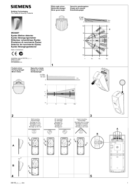
HE-110
(cod. HE110), HE-111 (cod. HE111),
Doppio rivelatore passivo d'infrarossi ad effetto tenda
per finestre e porte a basso assorbimento per sistemi senza fili
ISTRUZIONI D’INSTALLAZIONE
COLLEGAMENTI
A
A
Spazio per l’alloggiamento del trasmettitore
⌧
a.
Colore filo Funzione
Rosso
Positivo 3 Vc.c. alimentazione trasmettitore
Nero*
Negativo alimentazione trasmettitore
Giallo
Uscita allarme N.C. [email protected]. (open collector riferito a negativo)
Verde
Contatto antiapertura COM
Verde
Contatto antiapertura N.C.
vi
st
Numero
it
Antiapertura
Fig. 1
* Nel caso di utilizzo di un’altra batteria per l’alimentazione del trasmettitore, occorre collegare questo filo al negativo del trasmettitore per il corretto funzionamento dell’uscita d’allarme del rivelatore.
Non utilizzare, in questo caso, il filo rosso (positivo di alimentazione)
DESCRIZIONE
w
w
.te
Esempio d’installazione
le
Il rivelatore installato sullo stipite superiore di una finestra o di una porta, tra l’infisso e la relativa tapparella o persiana fornisce una protezione ad effetto tenda mediante una coppia di sensori passivi d’infrarossi.
AREE DI RILEVAZIONE (m)
Vista laterale
Vista frontale
2
34°
0.5
1.2
CONSIGLI PER L'INSTALLAZIONE
w
- Evitare i raggi solari diretti
- Evitare di fissare il rivelatore in luoghi esposti ad agenti atmosferici (pioggia, vento, ampie variazioni termiche, ecc…)
- Evitare che il rivelatore possa essere influenzato da oggetti riflettenti (pozzanghere, vetro, ecc.)
INSTALLAZIONE
Posizionare il rivelatore al centro dello stipite superiore della finestra o della porta da proteggere, tra
l'infisso e la tapparella o persiana, segnare sul muro la posizione dei fori di fissaggio (Fig. 1 fori A); praticare i due fori utilizzando una punta Ø 5mm, ed inserire nei fori i tasselli inclusi nella confezione.
REGOLAZIONI
DIP 1 - Conteggio impulsi
Off = 1 impulso
On = 2 impulsi
DIP 3 - Funzionamento LED
Off = Accensione LED disabilitata
On = Accensione LED asservita all’allarme
ATTENZIONE: Il funzionamento del LED riduce l'autonomia della batteria.
DIP 4 - Alimentazione
Off = Rivelatore non alimentato
On = Rivelatore alimentato
a.
it
DIP 2 - Funzionamento AND/OR
Off = Funzionamento in AND
(Alta immunità ai falsi allarmi)
On = Funzionamento in OR
(Bassa immunità ai falsi allarmi)
vi
st
Chiudere il coperchio del rivelatore utilizzando le viti 3x30 incluse nella confezione.
Controllare l'area di copertura del rivelatore.
SOSTITUZIONE BATTERIA
Per sostituire la batteria occorre togliere alimentazione al rivelatore (DIP 4 = Off), dissaldare i terminali della batteria esaurita e sostituirla con una nuova batteria modello SAFT LS17500 rispettando la
polarità. Ripristinare l'alimentazione del rivelatore (DIP 4 = On).
le
PROGRAMMAZIONE DEL TRASMETTITORE
Fare riferimento al manuale di programmazione del sistema utilizzato.
Alimentazione
Assorbimento
Tipo di lente
da 3.6 Vc.c. a 6 Vc.c. (installata pila al Litio 3.6 Vc.c.)
a riposo
75 µA
in allarme 900 µA
Fresnel
4
w
Zone di rilevazione
.te
CARATTERISTICHE
Conteggio impulsi
1 o 2 impulsi in 2.5 s
Relè d'allarme
N.C. [email protected].
contatto N.C., si apre alla rimozione del coperchio
selezionabile On/Off, da mettere tassativamente in Off
al termine dell’installazione
Compensazione della temperatura automatica
Temperatura di funzionamento
da -20°C a +50°C
Umidità ambientale
85% (max)
Grado di protezione
IP54
Dimensioni LxAxP (mm)
280x40x30
Peso g
157
w
w
Antiapertura
Indicatore LED
www.hesa.com • e-mail: [email protected]
DT01329HE0710R02
AVVERTENZA
Questa apparecchio è progettato per rilevare movimenti ed attivare una centrale d'allarme. Essendo solo
una parte di un sistema completa, non si possono assumere responsabilità in caso di furto o danni.
HE-110
(cod. HE110), HE-111 (cod. HE111)
Double infrared passive detector with curtain effect for
windows and doors (low current version for wireless systems)
INSTALLATION INSTRUCTIONS
DESCRIPTION
The detector, set up on the top of the window or door frame, between the frame and the roller blind
or shutter, offers a protection with curtain effect by means of a pair of infrared passive sensors.
Example of installation
DETECTION AREA: (m)
Front view
it
Side view
a.
2
34°
0.5
vi
st
SUGGESTIONS ON THE INSTALLATION
1.2
- Avoid direct sunrays
- Avoid fixing the detector in places exposed to atmospheric agents (rain, wind, big thermical
changes ecc…)
- Avoid fixing the detector near reflecting objects that might influence it (puddle, glass, strobe lights etc..)
INSTALLATION:
CONNECTIONS
A
.te
le
Place the detector in the middle of the window or door frame that is to be protected, draw on the wall
the position of the holes for the fixing between the frame and the roller blind or shutter (Fig. 1 A holes);
make the two holes using 5mm drill bit and insert the plugs that are included in the pack.
Make a hole in the plastic bottom enclosure of the detector where a knock-out hole is positioned to
allow the passing of the cable (Fig. 1 position B)
Space for placing the transmitter
w
w
⌧
A
Fig. 1
Wire Color
Red
Black*
Yellow
Green
Green
w
Number
Antiopening tamper
Function
Positive 3Vdc transmitter power supply
Negative transmitter power supply
Alarm NC Output [email protected]. (open collector referred to negative)
Antiopening contact COM
Antiopening contact NC
* In case another battery is used to power the transmitter, this wire must be connected to the negative of the transmitter for the correct operation of the alarm output of the detector.
In this case, don't use the red wire (positive power supply)
ADJUSTMENTS:
DIP 3 - LED operation
Off = LED disabled
On = LED follows alarm status
WARNING: LED operation reduces the autonomy of
the battery.
DIP 2 - Operation AND/OR
Off = AND (high immunity to false alarms)
On = OR (low immunity to false alarms)
DIP 4 - Power supply
Off = Detector not powered
On = Detector powered
a.
it
DIP 1 - Pulse count
Off = 1 pulse
On = 2 pulses
BATTERY REPLACEMENT:
vi
st
Close the lid of the detector using the 3x30 mm screws that are included in the package.
Check the detection area of the detector.
In order to replace the battery you must remove the power supply from the detector (DIP 4 = OFF), by
unsoldering the terminals of the exhausted battery and replace it with a new one (type SAFT LS17500)
respecting the polarity. Reset the detector's power supply (DIP 4 = ON )
TRANSMITTER PROGRAMMING:
Power supply
Current absorption
Lens type
from 3.6VDC to 6VDC (3.6 VDC Lithium battery installed)
.te
CHARACTERISTICS:
le
Refer to the programming instructions of the system used.
Rest condition 75 µA
Alarm condition 900 µA
Fresnel
Detection zones
1 or 2 pulses in 2.5s
N.C. 100mA@50VDC.
Antiopening
N.C. contact, opens when the lid is removed
LED indicator
ON/OFF selectable, that must be set to OFF once
the installation is completed
Temperature compensation
automatic
Operating Temperature
from -20° to + 50° C
Humidity
85% (max)
Grade of protection
IP54
Dimensions LxHxD (mm)
280x40x30
Weight g
157
w
Allarm relay
w
w
Number of pulses
4
DT01329HE0710R02
WARNING:
This device is designed to detect movements and trigger an alarm security system. Being only a part
of the complete system, the manufacture cannot be responsible in case of theft or damages.
Scarica