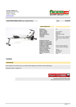
'75;6
MANUALE
D’USO
INDICE
INDICE ....................................................................................................................................................................................1
INTRODUZIONE .....................................................................................................................................................................2
Contenuto dell’imballaggio ........................................................................................................................................................................ 2
Cosa contiene questo manuale ................................................................................................................................................................. 2
Convenzioni tipografiche ........................................................................................................................................................................... 2
NORME DI SICUREZZA.........................................................................................................................................................2
DATI DI MARCATURA ...........................................................................................................................................................3
DESCRIZIONE DEL RICEVITORE DTRX3............................................................................................................................3
Caratteristiche ........................................................................................................................................................................................... 3
Apparecchi compatibili per l’uso con il ricevitore DTRX3 ....................................................................... ................................................... 3
Esempio di installazione ............................................................................................................................................................................ 4
Cavi............................................................................................................................................................................................................ 4
INSTALLAZIONE ....................................................................................................................................................................5
Apertura dell’imballaggio ........................................................................................................................................................................... 5
Controllo della marcatura .......................................................................................................................................................................... 5
Dip-Switch e Jumper di configurazione ..................................................................................................................................................... 6
CONFIGURAZIONE DEL RICEVITORE ................................................................................................................................6
Impostazione del numero di identificazione del ricevitore ......................................................................................................................... 7
Modalità di comunicazione del DTRX3 ...................................................................................................................................................... 7
Inserimento del carico nella linea RS485 .................................................................................................................................................. 7
Tipo di ottiche controllate........................................................................................................................................................................... 7
Impostazione della velocità di comunicazione........................................................................................................................................... 7
Impostazione della tensione di controllo del brandeggio e tergicristallo (Wiper)....................................................................................... 8
Impostazione degli ausiliari AUX3 / AUX4................................................................................................................................................. 8
Collegamento con l’unità di comando........................................................................................................................................................ 8
Collegamento con la linea RS485 ............................................................................................................................................................. 8
Collegamento di più ricevitori in cascata (collegamento punto-punto) .................................................................................................. 9
Più ricevitori per linea, collegamento con doppino twistato (collegamento multipunto)...................................................................... 10
Configurazioni miste (punto-punto /multipunto) ................................................................................................................................... 10
Collegamento con la linea Current Loop ................................................................................................................................................. 11
Collegamento con la linea RS232 ........................................................................................................................................................... 12
Regolazione della tensione di controllo dell’ottica ................................................................................................................................... 12
Collegamento dei cavi del brandeggio e delle ottiche ............................................................................................................................. 12
SETTAGGIO DEL RICEVITORE PER LE FUNZIONI DI PRESET ......................................................................................12
TEST DEL RICEVITORE DTRX3 .........................................................................................................................................13
USO DEI CONTATTI DI ALLARME .....................................................................................................................................13
Modalità di funzionamento di AUX4......................................................................................................................................................... 13
TASTI LOCALI MOVIMENTO BRANDEGGIO.....................................................................................................................14
ACCENSIONE E SPEGNIMENTO........................................................................................................................................14
MANUTENZIONE..................................................................................................................................................................14
RISOLUZIONE DI PROBLEMI .............................................................................................................................................15
TABELLA CONFIGURAZIONE DIP SWITCH SW4 .............................................................................................................15
Il produttore declina ogni responsabilità per eventuali danni derivanti da un uso improprio delle apparecchiature menzionate in
questo manuale; si riserva inoltre il diritto di modificarne il contenuto senza preavviso. Ogni cura é stata posta nella raccolta e nella
verifica della documentazione contenuta in questo manuale: tuttavia il produttore non può assumersi alcuna responsabilità
derivante dall’utilizzo della stessa. Lo stesso dicasi per ogni persona o società coinvolta nella creazione e nella produzione di
questo manuale.
Pag. 1
DTRX3 3701
Introduzione
Contenuto dell’imballaggio
• 1 ricevitore DTRX3
• 1 manuale d’uso
• 2 tappi di chiusura PG11
• 4 staffe di fissaggio a muro con relative viti
Alla consegna del prodotto verificare che l’imballo sia integro e non abbia segni evidenti di cadute o abrasioni. In caso
di evidenti segni di danno all’imballo contattare immediatamente il fornitore.
Controllare che il contenuto sia rispondente alla lista del materiale sopra indicata.
Cosa contiene questo manuale
In questo manuale è descritto il ricevitore DTRX3, con le particolari procedure di installazione, configurazione e utilizzo.
E’ necessario leggere attentamente questo manuale, in particolar modo il capitolo concernente le norme di
sicurezza, prima di installare ed utilizzare il ricevitore.
Convenzioni tipografiche
Nel presente manuale si fa uso di diversi simboli grafici, il cui significato è riassunto di seguito:
Rischio di scosse elettriche; togliere l’alimentazione prima di procedere con le operazioni, se non é
espressamente indicato il contrario.
L’operazione é molto importante per il corretto funzionamento del sistema: si prega di leggere attentamente la
procedura indicata, ed eseguirla secondo le modalità previste.
Descrizione delle caratteristiche del sistema: si consiglia di leggere attentamente per comprendere le fasi
successive.
Norme di sicurezza
Il ricevitore DTRX3 é conforme alle normative vigenti all’atto della pubblicazione del presente manuale per
quanto concerne la sicurezza elettrica, la compatibilità elettromagnetica ed i requisiti generali.
Si desidera tuttavia garantire gli utilizzatori (tecnico installatore e operatore) specificando alcune avvertenze per
operare nella massima sicurezza:
• Collegare ad una linea di alimentazione corrispondente a quella indicata sulle etichette di marcatura (vedere il
successivo capitolo Dati di marcatura)
• La presa di alimentazione deve essere connessa a terra secondo le norme vigenti
• Prima di spostare o effettuare interventi tecnici sull’apparecchio, disinserire l‘alimentazione
• Non utilizzare cavi di tensione con segni di usura o invecchiamento, in quanto rappresentano un grave pericolo per
l’incolumità degli utilizzatori
• L’installazione dell’apparecchio (e dell’intero impianto di cui esso fa parte) deve essere effettuata da personale
tecnico adeguatamente qualificato
• L’apparecchio deve essere aperto soltanto da personale tecnico qualificato. La manomissione dell’apparecchio fa
decadere i termini di garanzia
• Non utilizzare l’apparecchio in presenza di sostanze infiammabili
• Non permettere l’uso dell’apparecchio a bambini o incapaci
• Accertarsi che l’apparecchio sia fissato in maniera solida ed affidabile
• L’apparecchio si considera disattivato soltanto quando l’alimentazione é disinserita e i cavi di collegamento con altri
dispositivi sono stati rimossi
• Prima dell’alimentazione del DTRX3 installare un dispositivo di protezione nell’impianto elettrico dell’edificio
• Per l’assistenza tecnica rivolgersi esclusivamente al personale tecnico autorizzato
• Conservare con cura il presente manuale per ogni futura consultazione
Pag. 2
DTRX3 3701
Dati di marcatura
Sul ricevitore DTRX3 sono riportate due etichette.
La prima etichetta contiene:
• Codice di identificazione del modello (Codice a barre Extended 3/9 )
• Tensione di alimentazione (Volt)
• Frequenza (Hertz)
• Consumo (Watt)
La seconda etichetta indica il numero di serie del modello (Codice a barre Extended 3/9)
All’atto dell’installazione controllare se le caratteristiche di alimentazione del ricevitore corrispondono a quelle richieste.
L’uso di apparecchi non idonei può portare a gravi pericoli per la sicurezza del personale e dell’impianto.
Descrizione del ricevitore DTRX3
Il ricevitore DTRX3 è un ricevitore di comandi a microprocessore per il controllo remoto di brandeggi, ottiche
motorizzate, tergicristallo, pompa-lavavetri e funzioni ausiliarie.
Caratteristiche
• 17 Funzioni : UP, DOWN, LEFT, RIGHT, AUTO,WASHER,WIPER, ZOOM TELE, ZOOM WIDE, FOCUS NEAR,
FOCUS FAR, IRIS OPEN, IRIS CLOSE, AUX1, AUX2, AUX3, AUX4
• Alimentazione telecamera 12 Vîýmax 350mA (AUX1) e 24 V~ max 180mA (AUX2)
• 2 Contatti puliti portata 1A 230V~ 1A 24VÚ ( AUX3, AUX4 )
• 999 indirizzi selezionabili tramite Dip Switch
• Ingresso seriale selezionabile tra RS232 / Current Loop / RS485
• Velocità di comunicazione selezionabile ( 19200 / 9600 /1200 / 300 Baud)
• Ripetitore RS232, RS485 e Current Loop per configurazione in cascata
• Possibilità di usare sia ottiche funzionanti ad inversione di polarità che ottiche funzionanti a filo comune
• Led presenza alimentazione
• Led funzione attiva
• EEPROM per memorizzazione opzioni attive
• Microcontrollore 16 bit con memoria Flash riprogrammabile
• Trimmer regolazione tensione ottica (3î - 12 Vî)
• Funzioni PRESET / SCAN / PATROL con autoriconoscimento delle funzioni presenti
• Possibilità di memorizzare fino a 14 posizioni di PRESET (brandeggio, ottica)
• 4 contatti di allarme impostabili N.A. o N.C.
• Tensione di alimentazione:
230 V~ 50 Hz
• Consumo:
60 W
• Max potenza commutabile:
100 W
• Tensione alimentazione brandeggio:
24/230 V~ 50 Hz selezionabile
• Tensione alimentazione tergicristallo:
24/230 V~ 50 Hz selezionabile
• Tensione alimentazione pompa lavavetro:
230 V~ 50/60 Hz
• Tensione alimentazione ottica:
3îý- 12 Vî (max 100mA)
• Temperatura di esercizio:
0 - 50°C
• Fusibili:
F2: 1 AF 250V
F5: 2.5 AF 250V
• Dimensioni:
337 x 237 x 128mm
• Peso (netto):
3,6 kg.
Apparecchi compatibili per l’uso con il ricevitore DTRX3
• DCS3, DCS2, DCMT8: tastiere di controllo.
• PTH310/PTH310P, PTH311/PTH311P, PTH910/PTH910P, PTH911P/PTH911P, NXPTH210, NXPTH211C:
brandeggi.
• DCMX: controllore di comunicazioni
• DCRE485: distributore di dati seriali
Fare riferimento ai singoli manuali d’uso per una descrizione completa delle caratteristiche degli apparecchi.
Pag. 3
DTRX3 3701
Esempio di installazione
Un operatore con più monitor, con controllo di una serie di brandeggi in configurazione mista:
MATERIALE IMPIEGATO:
Tastiere di controllo:
DTRX3
DTRX3
DTRX3
• 1 tastiera di controllo DCS3
Gestione video:
• 2 monitor
• 3 telecamere (+1 nel ricevitore OEM)
• 1 matrice video SW328
OEM
Gestione telemetria:
SW328
• 3 ricevitori DTRX3
• 3 brandeggi PTH910P
• 1 ricevitore OEM (con camera incorporata)
DCS3
Cavi
Negli schemi d’esempio sono stati utilizzati diversi tipi di tratto per indicare cavi di diversa funzione:
cavo telefonico:
1,5 m. fornito in dotazione con la tastiera.
cavo video:
Coassiale RG 59 o cavo equivalente.
Per lunghe distanze si consiglia un sistema di trasmissione video su doppino twistato.
cavo multipolare:
ogni funzione di controllo del brandeggio viene attivata / disattivata da un relè interno al ricevitore.
Stabilire il numero finale di cavi, seguendo le indicazioni seguenti:
7 fili per la movimentazione del brandeggio (230 V~ o 24 V~): destra, sinistra, alto, basso, autopan, comune, terra
(solo per 230 V~)
6 fili di controllo per ottiche ad inversione di polarità (zoom, focus, iris)
4 fili di controllo per ottiche a filo comune (zoom, focus, iris)
7 fili per la gestione del preset: 5 collegati ai potenziometri di riferimento, +5 V î e massa
Pag. 4
DTRX3 3701
4 fili per il Wiper
3 fili per il Washer
2 fili per ciascun ausiliare utilizzato
3 fili per cavo alimentazione
Nota: è consigliato l’utilizzo di differenti cavi multipolari per le funzioni in bassa tensione ed in alta tensione.
Sezione minima consigliata:
0,56 mm.² (AWG 20) per fili in alta tensione (brandeggio, wiper, washer)
0,34 mm.² (AWG 22) per fili in bassa tensione (ottica, ausiliari, preset)
0,75 mm.² (AWG 18) per fili alimentazione del DTRX3
cavo per la ricezione/trasmissione digitale dei comandi:
2 fili per la ricezione dall’unità di comando (doppino telefonico twistato, sezione 0,22 mm.² AWG 24)
2 fili per la eventuale trasmissione al ricevitore successivo nelle configurazione in cascata (doppino telefonico
twistato, sezione 0,22 mm.² AWG 24)
Nota: la distanza massima del collegamento é di circa 15 m in RS232; 1500 m in Current Loop; 1200 m in RS485.
Quando più ricevitori sono collegati in cascata, è necessario utilizzare due cavi separati per la ricezione e la
trasmissione digitale dei comandi ( non utilizzare cavi multicoppia ) tra i ricevitori.
Installazione
La fase di installazione deve essere effettuata solo da personale tecnico qualificato.
Le seguenti procedure sono da effettuare in assenza di alimentazione, se non diversamente indicato.
Apertura dell’imballaggio
Se l’imballaggio non presenta evidenti difetti (dovuti a cadute o abrasioni anomale), procedere al controllo del materiale
in esso contenuto, secondo la lista fornita al paragrafo Contenuto dell’imballo al capitolo Introduzione.
I materiali d’imballo sono costituiti interamente da materiale riciclabile. Sarà cura del tecnico installatore smaltirli
secondo le modalità di raccolta differenziata o comunque secondo le norme vigenti nel Paese di utilizzo.
Controllo della marcatura
Prima di procedere con l’installazione controllare se il materiale fornito corrisponde alle specifiche richieste,
esaminando le etichette di marcatura, secondo quanto descritto al capitolo Descrizione della marcatura.
Non effettuare per nessun motivo alterazioni o collegamenti non previsti in questo manuale: l’uso di apparecchi non
idonei può portare a gravi pericoli per la sicurezza del personale e dell’impianto.
Pag. 5
DTRX3 3701
Dip-Switch e Jumper di configurazione
Nella figura seguente identificare i dip-switch ed i jumper di configurazione del ricevitore:
SW5
Configurazione del ricevitore
La fase di configurazione del ricevitore consente di predisporlo ad un funzionamento ottimale, in base alle
necessità dell’impianto.
La configurazione deve essere fatta solo al momento dell’installazione da parte del tecnico installatore.
Si consiglia di procedere con ordine alla configurazione dei parametri, per evitare problemi di installazione.
I settaggi impostati in fase di configurazione sono:
• Impostazione del numero di identificazione del ricevitore
• Modalità di comunicazione
• Tipo di ottiche controllate
• Impostazione della velocità di comunicazione
• Impostazione della tensione di controllo del brandeggio e tergicristallo (Wiper)
• Impostazione degli ausiliari AUX3 / AUX4
• Collegamento con l’unità di comando
• Regolazione della tensione di controllo dell’ottica
• Collegamento dei cavi del brandeggio e delle ottiche
• Impostazione degli allarmi
• Operazione di Test delle funzioni attive del ricevitore (per operazioni di PRESET)
Pag. 6
DTRX3 3701
Impostazione del numero di identificazione del ricevitore
Configurare i dip-switch SW1, SW2 e SW3 in base all’indirizzo che si vuole attribuire al ricevitore nel modo seguente :
SW1 : Centinaia
SW2 : Decine
SW3 : Unità
ESEMPI:
Indirizzo ricevitore n.359
Impostare SW1 a 3, SW2 a 5 e SW3 a 9.
Indirizzo ricevitore n.27
Impostare SW1 a 0, SW2 a 2 e SW3 a 7.
Indirizzo ricevitore n.4
Impostare SW1 a 0, SW2 a 0 e SW3 a 4.
Modalità di comunicazione del DTRX3
In base al tipo di comunicazione che si sceglie eseguire le seguenti impostazioni:
Current Loop: JP2 e JP3 in posizione CL
RS485:
Vedi sotto (inserimento del carico nella linea RS485)
RS232:
Non è necessaria alcuna impostazione
Inserimento del carico nella linea RS485
Dove agire: JumperJP5 e JP6
JP5 in posizione A: carico inserito in ricezione RS485
JP5 in posizione B: carico disinserito in ricezione RS485
JP6 in posizione A: carico inserito in trasmissione RS485
JP6 in posizione B: carico disinserito in trasmissione RS485
Tipo di ottiche controllate
ATTENZIONE : La selezione errata del tipo di ottiche può causare il danneggiamento delle ottiche!
Il DTRX3 è in grado di controllare sia ottiche a inversione di polarità, sia a filo comune. In caso di ottiche a filo comune
collegare il filo comune a FOCUS-.
Impostazione della velocità di comunicazione
Previsto anche per l’uso in sistemi di trasmissione digitale, il DTRX3 può effettuare comunicazioni con una velocità da
300 a 19200 baud.
Dove agire: interruttori 1 e 2 di SW4
Impostazioni:
Interr. 1 Interr. 2
Velocità
OFF
OFF
9600 baud *
OFF
ON
1200 baud
ON
OFF
300 baud
ON
ON
19200 baud
* impostazione di default
ATTENZIONE: I’interruttore 8 di SW4 va sempre lasciato sulla posizione ON
Pag. 7
DTRX3 3701
Impostazione della tensione di controllo del brandeggio e tergicristallo (Wiper)
ATTENZIONE: La selezione errata di questo settaggio può comportare il danneggiamento del brandeggio e del
tergicristallo!
Controllare la tensione di funzionamento del brandeggio e del tergicristallo (Wiper): solitamente questa è indicata da
un’etichetta posta sull’oggetto.
Dove agire: Switcher SW5
Impostazioni:
alimentazione del brandeggio e del tergicristallo in 24 V~: SW5 in posizione 24V~
alimentazione del brandeggio e del tergicristallo in 230 V~: SW5 in posizione 230 V~.
Impostazione degli ausiliari AUX3 / AUX4
E’ possibile impostare il funzionamento degli ausiliari AUX3 / AUX4 settando lo switch 6 del dip SW4:
- switch 6 di SW4 su OFF (default): l’operatore deve premere il tasto di comando una volta per attivare l’ausiliare ed
una seconda volta per disattivarlo
- switch 6 di SW4 su ON: l’ausiliare rimane attivato sino a che l’operatore tiene premuto il relativo tasto di comando.
NB: l’ausiliario AUX4 è attivabile anche su contatto di allarme. Per una descrizione accurata di tale funzione andare al
paragrafo relativo ai contatti di allarme.
Collegamento con l’unità di comando
Il connettore RJ11 (vedi figura di pag.6) presente sul circuito consente la ricezione e la trasmissione di dati digitali in
RS232 o RS485 consentendo un rapido collegamento delle varie apparecchiature durante eventuali fasi di test, oppure
per il collegamento di intefacce di conversione presenti sul mercato (RS232-fibra ottica....).
Per il collegamento finale si consiglia di usare, nel caso si utilizzino tastiere di controllo DCS3, la modalità RS485 con i
relativi morsetti di collegamento (che consente di raggiungere una distanza massima di 1200m) o in alternativa, nel
caso vengano utilizzate tastiere di controllo DCS2, la modalità Current Loop (la distanza massima raggiungibile è di
1500 m).
Collegamento con la linea RS485
La tastiera DCS3 e il ricevitore DTRX3 possono essere collegati direttamente tramite il cavo telefonico fornito dal
fabbricante utilizzando il connettore RJ11 presente nel circuito, secondo la tabella di riferimento riportata di seguito.
Collegamento DCS3- ricevitore DTRX3
Modalità di comunicazione RS485: distanza max
1200 metri
DCS3 (RJ11 A o B)
TX-485A Bianco
TX-485B Giallo
-------------
DTRX3
DTRX3
Blu RX-485A
Nero RX-485B
Nota: Il ricevitore DTRX3 ha il carico inserito in ricezione ed è
collegato alla linea A o B della tastiera con il carico inserito.
Dal lato ricevitore è possibile anche collegarsi più semplicemente ai morsetti RX-485A e RX-485B secondo lo schema
seguente.
Pag. 8
DTRX3 3701
Collegamento di più ricevitori in cascata (collegamento punto-punto)
DCS3
I ricevitori DTRX3 possono rigenerare internamente il segnale ricevuto e rispedirlo su di una nuova linea di
comunicazione verso il ricevitore successivo. Ognuno dei tre tratti di linea (L1, L2, L3) è considerato indipendente, e
collega punto-punto solo due dispositivi, entrambi con carico inserito, per una lunghezza massima di 1200 metri. La
distanza tra tastiera e ricevitore D può quindi raggiungere i 3600 m (1200 m tra la tastiera ed il ricevitore B, 1200 m tra
il ricevitore B ed il ricevitore C, e altri 1200 m tra il ricevitore C ed il ricevitore D, per un totale di 3600 m).
DCS3
cavo telef.
RJjack
DTRX3
RS485A
connettori
bianco
------------------------
RX-485A
RS485B
RJ11 ‘A’ e ‘B’
giallo
------------------------
RX-485B
Nota: I morsetti RX-485A e RX-485B che presentano il carico inserito, devono essere collegati, rispettivamente, ai
morsetti TX-485A e TX-485B dell’unità precedente, anch’essi con il carico inserito:
NB: Nel caso del collegamento in questione (punto-punto ) il malfunzionamento di uno dei ricevitori comporta
l’interruzione dei dispositivi in cascata.
Pag. 9
DTRX3 3701
Più ricevitori per linea, collegamento con doppino twistato (collegamento multipunto)
Tutti i ricevitori collegati ad una stessa linea devono usare il medesimo protocollo di comunicazione RS485.
Per ciascuna delle linee valgono le seguenti considerazioni:
• solo una delle tastiere (quella posta ad un capo della linea) presenta il carico inserito
• solo uno dei ricevitori (posto all’altro capo della linea) presenta il carico inserito.
• la lunghezza complessiva della linea non deve superare i 1200 m.
È stata utilizzata la linea A della tastiera DCS3 per la comunicazione verso la telemetria. Gli estremi (Tastiera Ricevitore A3) devono avere la resistenza di terminazione inserita. I ricevitori A1, A2 non devono avere la resistenza di
terminazione inserita. La lunghezza massima della linea, da capo a capo (dalla tastiera al ricevitore A3), è di 1200
metri.
NB: Nel caso del collegamento in questione(multipunto), il malfunzionamento di uno dei dispositivi non influenza gli
altri ricevitori.
Configurazioni miste (punto-punto /multipunto)
Risulta essere una combinazione dei due modi di collegamento precedenti, e a seconda della combinazione scelta
consente di sfruttare al meglio i vantaggi delle due tipi di collegamento riducendo in maniera anche significativa la
possibilità di malfunzionamento.
Ecco un esempio di collegamento misto:
Nell’esempio
proposto,
un
eventuale blocco del ricevitore R3
(collegato in multipunto sulla linea
L3)
non
causa
il
malfunzionamento del ricevitore
R4.
R3 non è ai capi della linea L3, e
quindi non deve essere terminato.
Se il ricevitore R2 dovesse
bloccarsi, essendo questo il
‘generatore’ della linea L3, tutti i
ricevitori ad esso collegati in
cascata (R3 ed R4) non
riceveranno comandi.
Pag. 10
DTRX3 3701
Collegamento con la linea Current Loop
I diversi dispositivi (tastiera DCS2, matrice video SW164OSM e ricevitore DTRX3) possono essere collegati
direttamente tramite cavo telefonico fornito dal fabbricante:
Collegamento DCS2 - ricevitore DTRX3
DTRX3
SW164OSM
DCS2
Per le normali connessioni sul campo, fare riferimento ai collegamenti effettuati tramite le scatole di derivazione RJ,
fornite dal fabbricante, secondo le tabelle di riferimento riportate di seguito:
Modalità di Comunicazione Current Loop: distanza max 1500
metri
DTRX3. Jumper JP2 e JP3 posizione CL.
DCS2 /DCMT8
TX CL Giallo
GND CL Rosso
-------------
DCS2
DTRX3
DTRX3
Morsetto RX CL
Morsetto AGND
Nota: dal lato Ricevitore il collegamento deve essere effettuato
seguente:
ai morsetti RXCL e AGND secondo lo schema
• se il ricevitore è collegato in cascata ad un’altra unità DTRX3, la modalità di ricezione deve essere settata in
Current Loop con i jumper JP2 e JP3 in posizione CL.
• i morsetti RX CL e AGND devono essere collegati, rispettivamente, ai morsetti TX CL e AGND dell’unità precedente
secondo il seguente schema:
Pag. 11
DTRX3 3701
Collegamento con la linea RS232
DCS2
Collegamento RS232: distanza max 15 metri.
DCS2/DCMT8
TX RS232 Nero
GND RS232 Verde
-------------
DTRX3
DTRX3
Giallo RX RS232
Rosso GND RS232
Regolazione della tensione di controllo dell’ottica
-collegare il cavo di alimentazione e alimentare l’unità DTRX3 ( LD1 acceso )
-inserire un carico tra i morsetti FOCUS NEAR e FOCUS FAR che assorba almeno 10mA (utilizzare una resistenza di
valore compreso tra 100 e 1000 ohm).
- posizionare i puntali del tester sui morsetti FOCUS NEAR e FOCUS FAR
- tenere premuto uno dei due tasti FOCUS sull’unità di comando
- regolare la tensione di controllo dell’ottica agendo sul trimmer TR1 ( default 12Vî )
NB: evitare di regolare la tensione a vuoto (senza inserire il carico) altrimenti la regolazione risulterà errata.
Collegamento dei cavi del brandeggio e delle ottiche
Attenzione: prima di effettuare le seguenti operazioni assicurarsi che la tensione di controllo del brandeggio e
l’impostazione del tipo di ottiche utilizzati siano corretti.
- togliere alimentazione all’unità
- effettuare i collegamenti con ottica e brandeggio
- dare alimentazione all’unità
In caso di ottiche e brandeggi con funzioni di PRESET (PAN,TILT ZOOM FOCUS e IRIS, VCC e GND), la
lunghezza massima dei cavi di preset non deve superare i 5 metri di lunghezza, pena un non corretto posizionamento
sulle posizioni memorizzate.
Settaggio del ricevitore per le funzioni di PRESET
Il ricevitore DTRX3 presenta le funzioni di preset integrate(relative al brandeggio e alle ottiche). E’ possibile
memorizzare fino ad un massimo di 14 posizioni richiamabili tramite tastiera con le funzioni di Scan e Patrol. Il
ricevitore è in grado di riconoscere in maniera automatica mediante un test quali funzioni di preset sono presenti e
risulta pertanto agevole configurare il dispositivo. Tuttavia è necessario procedere con alcune precauzioni:
• Prima di effettuare il test del ricevitore (che determina quali funzioni di preset sono attive) assicurarsi di aver
collegato in maniera corretta i cavi relativi al brandeggio e alle ottiche.
• Per i cavi di preset (PAN, TILT, ZOOM, FOCUS,IRIS, VCC e GND) usare cavi di lunghezza non superiore ai 5
metri.
Pag. 12
DTRX3 3701
Test del ricevitore DTRX3
Dopo aver connesso i cavi per il brandeggio e l’ottica, per controllare il corretto funzionamento dei dispositivi e’
possibile lanciare una procedura di test automatico che rivelerà le funzioni disponibili.
ATTENZIONE: Il brandeggio, durante il test, si muove automaticamente. Non appoggiarsi ad esso, ne
frapporre ostacoli alla sua corsa.
Procedere secondo le seguenti indicazioni:
1. accendere il ricevitore
2. identificare il tasto freccia Up (tasto P4) e il tasto di reset (tasto P1)
3. tenendo premuto il tasto Up premere il pulsante di reset
4. rilasciare il tasto di reset (mantenendo il tasto Up premuto): inizia l’autotest
5. dopo l’inizio del test, rilasciare il tasto Up
Il ricevitore attiva una funzione alla volta, per circa 3 secondi:
• Pan: sinistra-destra (Led P)
• Tilt:
basso-alto (Led T)
• Zoom: wide-tele (Led Z)
• Focus: far-near (Led F)
• Iris:
close-open (Led I)
Il risultato del test e’ indicato dai 5 led P,T,Z,F,I ( posti nella parte del ricevitore vicina ai tasti freccia vedi figura a
pag.6). al termine del movimento di brandeggio ed ottiche:
• led acceso fisso: la funzione corrispondente (pan P, tilt T, zoom Z, focus F, iris I) opera correttamente
• led acceso lampeggiante: la funzione corrispondente non funziona correttamente oppure non è presente e non
puo’ essere utilizzata per le operazioni di preset/scan/patrol
Dopo qualche secondo dalla fine del test il ricevitore si resetta automaticamente per riprendere il funzionamento
normale.
ATTENZIONE! Un lampeggiamento di almeno uno dei led alla fine del test (a meno che la funzione non sia
assente) indica un malfunzionamento al quale si deve porre rimedio prima della messa in opera del ricevitore!
Uso dei contatti di allarme
I quattro contatti di allarme presenti nel ricevitore DTRX3 sono associati alle prime quattro posizioni di preset; se
l’allarme è attivato il brandeggio e l’ottica si portano nella posizione di preset corrispondente; l’ultimo allarme arrivato ha
sempre la priorità più alta. E’ possibile che il DTRX3 riceva un comando di allarme anche attraverso le tastiera di
comando DCS2, DCS3 (che lo ricevono a sua volta dalle matrici SW328 e SW164OSM), in tal caso brandeggio ed
ottica si portano nella posizione di preset n.1.
Per poter usare i contatti di allarme è necessario impostare i dip di SW4 come segue:
•
•
•
•
switch 3 di SW4 in posizione ON: contatti di allarme attivati
switch 3 di SW4 in posizione OFF: contatti di allarme disattivati
switch 4 di SW4 in posizione ON : contatti normalmente aperti
switch 4 di SW4 in posizione OFF : contatti normalmente chiusi
Modalità di funzionamento di AUX4
Dove agire : switch 5 di SW4
Impostazioni:
• interruttore 5 di SW4 OFF: funzionamento normale
interruttore 5 di SW4 ON: AUX4 si attiva al pervenire di un allarme e si disattiva al cessare del segnale di allarme
Pag. 13
DTRX3 3701
Tasti locali movimento brandeggio
Il ricevitore DTRX3 presenta 4 tasti locali (su scheda) per il movimento del brandeggio nelle quattro direzioni (Up,
Down, Left, Right, vedere figura a pag.6) molto utili in fase di installazione per movimentare il brandeggio al fine di
controllare la posizione dei finecorsa e/o la corretta installazione del brandeggio. I tasti freccia hanno priorità assoluta e
pertanto quando premuti disattivano momentaneamente l’utilizzo remoto (tramite tastiere) del ricevitore. Quando i tasti
freccia sono rilasciati la funzionalità del ricevitore ritorna ad essere pienamente ripristinata.
Il tasto Up in combinazione con il tasto di reset serve ad eseguire l’autotest (vedere paragrafo relativo Test del
ricevitore DTRX3).
Accensione e spegnimento
Prima di fornire alimentazione:
• controllare se il materiale fornito corrisponde alle specifiche richieste, esaminando le etichette di marcatura,
secondo quanto descritto al capitolo Descrizione della marcatura.
• controllare che i fusibili di protezione del ricevitore DTRX3 siano integri
• controllare che il ricevitore e gli altri componenti dell’impianto siano chiusi e sia quindi impossibile il contatto diretto
con parti in tensione.
• accertarsi che tutte le parti siano fissate in maniera solida ed affidabile
• i cavi di alimentazione non devono essere d’intralcio alle normali operazioni del tecnico installatore ed al movimento
del brandeggio.
• controllare che le fonti di alimentazione ed i cavi di collegamento eventualmente utilizzati siano in grado di
sopportare il consumo del sistema
Manutenzione
Il ricevitore DTRX3 non necessita di particolare manutenzione.
Si raccomanda di installarlo in modo che i cavi di alimentazione e di collegamento siano in posizione tale da non
essere causa di intralcio al movimento del brandeggio.
Pag. 14
DTRX3 3701
Risoluzione di problemi
Il ricevitore DTRX3 è caratterizzato da una notevole facilità d’uso, ma ciononostante possono insorgere dei
problemi sia in fase di installazione, di configurazione o durante l’uso.
PROBLEMA
Il led LD1 è spento
PROBABILE CAUSA
• Manca alimentazione
• Fusibile bruciato
• Configurazione errata della
ricezione
• Collegamento non corretto
• Identificazione DTRX3 errata
• Blocco dell’unità
Il led LD1 è acceso.
Non vengono eseguiti i
comandi
Il brandeggio non funziona
• Alimentazione del brandeggio
errata
L’ottica non funziona
• Tensione ottica errata
• Errata configurazione dei Dip
allarmi
In un collegamento a cascata, • Collegamento non corretto
le unità successive non
• Configurazione errata della
ricevono comandi
ricezione
• Errata configurazione del Dip
switch
Gli allarmi non funzionano
RIMEDIO
• Controllare il cavo di alimentazione
• Sostituire il fusibile F5
• In caso ricezione RS485 controllare di
aver/non aver inserito il carico con il
jumper JP5. In caso di ricezione in current
loop controllare che i jumper JP2 e JP3
siano in posizione CL
• Controllare i cavi di collegamento
• Controllare il numero di identificazione del
DTRX3 (SW1-SW2-SW3)
• Premere il pulsante di reset P1 o togliere
alimentazione
• Controllare che la tensione di
alimentazione del brandeggio corrisponda
a quella fornita dal ricevitore
• Controllare la regolazione del trimmer TR1
• Controllare l’impostazione dei dip 3, 4 e 5
di SW4
• Controllare i cavi di collegamento
• In caso trasmissine RS485 controllare di
aver/non aver inserito il carico con il
jumper JP6. In caso di trasmissione in
current loop controllare che i jumper JP2 e
JP3 siano in posizione CL
• Controllare l’impostazione dell’indirizzo
delle unità non funzionanti.
Tabella configurazione Dip Switch SW4
Switch
1
1
1
1
2
2
2
2
3
3
4
4
5
5
6
6
7
8
NOTE:
Stato
Funzione
OFF OFF
ON OFF
OFF ON
ON ON
OFF
ON
OFF
ON
OFF
ON
OFF
ON
OFF
ON
9600 baud *
300 baud
1200 baud
19200 baud
Allarmi non usati *
Allarmi usati
Allarmi N.C. *
Allarmi N.O.
Allarmi su Aux4
Aux3 e Aux4 a rilascio
Lasciare questo switch sempre ON **
* Impostazioni di default
** Indispensabile per un corretto funzionamento del ricevitore
Pag. 15
DTRX3 3701
'75;6
OPERATING
INSTRUCTIONS
TABLE OF CONTENTS
TABLE OF CONTENTS..........................................................................................................................................................1
INTRODUCTION.....................................................................................................................................................................2
Contents of the packaging......................................................................................................................................................................... 2
Contents of this manual............................................................................................................................................................................. 2
Typographical conventions ........................................................................................................................................................................ 2
SAFETY RULES .....................................................................................................................................................................2
OPERATING DATA ON THE RATING PLATE ......................................................................................................................3
DESCRIPTION OF THE DTRX3 RECEIVER .........................................................................................................................3
Features .................................................................................................................................................................................................... 3
Compatible devices for the use with the DTRX3 receiver.......................................................................................................................... 3
Installation examples ................................................................................................................................................................................. 4
Cables ....................................................................................................................................................................................................... 4
INSTALLATION ......................................................................................................................................................................5
Unpacking.................................................................................................................................................................................................. 5
Control of the operating data on the rating plate ....................................................................................................................................... 5
Dip-switches and Configuration jumpers ................................................................................................................................................... 6
CONFIGURATION OF THE RECEIVER ................................................................................................................................6
Identification number of the receiver ......................................................................................................................................................... 7
DTRX3 receiving mode.............................................................................................................................................................................. 7
Setting of RS485 line load ......................................................................................................................................................................... 7
Type of lenses used................................................................................................................................................................................... 7
Communication speed............................................................................................................................................................................... 7
Control voltage of the positioning device and the wiper ............................................................................................................................ 8
AUX3 / AUX4 auxiliary devices.................................................................................................................................................................. 8
Connection with the control unit................................................................................................................................................................. 8
Connection with the RS485 line................................................................................................................................................................. 8
Connecting more than one receiver in cascade (point-to-point connection).......................................................................................... 9
More than one receiver per line, connection with twisted pair cable (multipoint connection) .............................................................. 10
Mixed configurations (point-to-point /multi-point)................................................................................................................................. 10
Connection with the Current Loop line..................................................................................................................................................... 11
Connection with the RS232 line............................................................................................................................................................... 12
Adjusting the voltage of the optics controls ............................................................................................................................................. 12
Connecting the pan&tilt and optics cables............................................................................................................................................... 12
SETTING THE RECEIVER FOR PRESET FUNCTIONS .....................................................................................................12
TESTING THE DTRX3 RECEIVER ......................................................................................................................................13
USE OF THE ALARM CONTACTS ......................................................................................................................................13
Operation mode of AUX4......................................................................................................................................................................... 13
LOCAL KEYS FOR P&T MOTOR MOVEMENT ..................................................................................................................14
SWITCHING ON AND SWITCHING OFF.............................................................................................................................14
MAINTENANCE ....................................................................................................................................................................14
TROUBLESHOOTING..........................................................................................................................................................15
DIP SWITCH SW4 CONFIGURATION TABLE ....................................................................................................................15
The manufacturer assumes no responsability for possible damages resulting from an improper use of the devices
mentioned in this manual; moreover he reserves the right to change the contents of the present manual without notice.
The documentation contained in this manual has been gathered and examined with great care; nevertheless the
manufacturer can not assume any responsability resulting from the use of such documentation. The same is valid for
any other person or society involved in the creation and in the production of the present manual.
Page 1
DTRX3 3701
Introduction
Contents of the packaging
• 1 DTRX3 receiver
• 1 user’s manual
• 2 PG11 blanking caps
• 4 wall mounts with relevant fastening screws
On delivery, please make sure that the packaging does not present damages or evident signs of falls or scratches.
In case of evident damages , contact immediately the supplier.
Please, make sure that the contents correspond to the components list mentioned above.
Contents of this manual
This manual contains the description of the DTRX3 receiver, with the relevant installation, configuration and use
procedures. Before installing and using the receiver it is necessary to read carefully the present manual, in
particular the section concerning the safety rules.
Typographical conventions
The following section illustrates the meaning of the several graphic symbols used in the present manual:
Risk of electric shock; before proceeding with the operations, if not otherwise stated, disconnect the unit.
The operation is very important for the correct functioning of the system: please read carefully the procedure
indicated and carry it out according to the prescribed specifications.
Description of the system features; we recommend reading carefully the sections marked with this symbol in
order to understand the phases which follow.
Safety rules
The DTRX3 receiver complies with the rules in force at the time of publication of the present manual as regards
the electric safety, the electromagnetic compatibility and the other general requirements.
Nevertheless we would like to assure the users (installer and operator) illustrating some measures to be adopted in
order to guarantee the maximum safety:
• The installation of the unit (and of the whole plant of which this unit is part) must be carried out by adequately skilled
technical personnel
• The unit must be opened only by skilled technical personnel. The warranty limits does not cover damages resulting
from an improper use of the unit
• Connect the unit to a power supply corresponding to the one indicated on the rating plate (see next section
Operating data on the rating plate)
• The outlet must be adequatly grounded according to the rules in force
• Before moving or carrying out technical operations on the unit, disconnect it
• Do not use worn or damaged power cords, since they represent a serious risk for the user’s safety
• Do not use the device in areas containing inflammable substances
• Do not allow children or unskilled persons to use the unit
• Make sure that the unit is fixed securely and firmly
• The unit is considered off-line only when the power supply is disconnected and the cables aimed to connect the unit
with other devices have been removed
• In front of the power-supply (DTRX3) a protection device must be installed in the electrical installation of the building
• For the after-sales service, please contact exclusively the authorized technical personnel
• Keep the present manual with care for any future consultation
Page 2
DTRX3 3701
Operating data on the rating plate
The DTRX3 receiver is supplied with two rating plates in conformity with the EC standards.
The first plate contains:
• Modell identification code (Extended 3/9 bar code)
• Power supply (Volt)
• Frequency (Hertz)
• Consumption (Watt)
The second plate indicates the serial number of the model (Extended 3/9 bar code).
During the installation phase, make sure that the power supply features of the receiver correspond to the
characteristics required. The use of unsuitable devices can lead to serious risks for the safety of the personnel and the
security of the plant.
Description of the DTRX3 receiver
The DTRX3 receiver is a microprocessor-based command receiver for the remote control of positioning
devices, motorized lenses, wiper, washer and auxiliary functions.
Features
• 17 Functions: UP, DOWN, LEFT, RIGHT, AUTO, WASHER, WIPER, ZOOM TELE, ZOOM WIDE, FOCUS NEAR,
FOCUS FAR, IRIS OPEN, IRIS CLOSE, AUX1, AUX2, AUX3, AUX4
• Power supplied to the camera: 12 VÙ max 350mA (AUX1) and 24 V~ max 180mA (AUX2)
• 2 dry contacts: range 1A 230V~ 1A 24VÚ (AUX3, AUX4)
• 999 selectable addresses
• Serial input selectable between RS-232 / Current Loop / RS485
• Selectable communication speed (19200 / 9600 / 1200 / 300 Baud)
• RS232, RS485 and Current Loop repeater for in-line configuration
• Possibility of using both polarity inversion lenses and common wire lenses
• Led indicating power supplied to the unit
• Led indicating active function
• EEPROM for the storage of active options
• 16 bit microcontroller with re-programmable Flash memory
• Trimmer for the adjustment of the lens voltage (from 3VÙ to 12VÙ)
• PRESET / SCAN / PATROL functions with an authomatic recognition of the existing functions
• Possibility to memorize up to 14 PRESET functions (Pan&Tilt motor, lens)
• 4 alarm contacts set as N.O. or N.C.
• Power supply:
230 V~ 50 Hz
• Consumption:
60 W
• Max switching power:
100W
• Power supplied to the positioning device: 24/230 V~ 50 Hz
• Power supplied to the wiper:
24/230 V~ 50 Hz
• Power supplied to the washer:
230 V~ 50/60 Hz
• Power supplied to the lens:
from 3VÙ to 12 VÙýmax 100mA
• Operating temperature:
0 – 50°C
• Fuses:
F2: 1 AF 250V
F5: 2.5 AF 250V
• Dimensions:
337 x 237 x 128mm
• Weight (net):
3,6 kg.
Compatible devices for the use with the DTRX3 receiver
• DCS3, DCS2, DCMT8: control keyboard.
• PTH310/PTH310P, PTH311/PTH311P, PTH910/PTH910P, PTH911P/PTH911P, NXPTH210, NXPTH211C: Pan &
Tilt motors
• DCMX: communications controller
• DCRE485: serial data distributor
Read the instruction manuals for the correct use of the above mentioned devices.
Page 3
DTRX3 3701
Installation examples
A single operator with several monitors for the control of a set of positioning devices in mixed configuration (star
configuration and cascade - chain configuration)
DEVICES:
Control keyboard:
DTRX3
DTRX3
DTRX3
•
1 DCS3 control keyboard
Video management:
•
•
•
OEM
2 monitors
3 cameras (+1 OEM receiver)
1 video matrix SW328
Telemetry management:
SW328
•
•
•
3 DTRX3 receivers
3 PTH910P P&t motors
1 OEM receiver (with camera included)
DCS3
Cables
Different types of stroke have been used in the example, in order to indicate cables with different functions:
phone cable:
1,5 m. equipped with the keyboard.
video cable:
RG 59 coaxial cable or equivalent cable.
For long distances a video transmission system on twisted pair is suggested.
multipolar cable:
each control function of the positioning device is activated /deactivated by a relay positioned inside the receiver.
Choose the final numbers of wires according to the following directions:
7 wires for the motion of the positioning device (230 V~ or 24 V~): right, left, up, down, autopan, common, ground
(only for 230 V~)
6 wires for the control of polarity reversal lenses (zoom, focus, iris)
4 wires for the control of common wire lenses (zoom, focus, iris)
7 wires for the preset control: 5 wires connected to the reference potentiometers, +5 VÙ and ground
4 wires for the wiper
3 wires for the washer
2 wires for each auxiliary device used
3 wires for the power supply cable
Note: We recommend using different multipolar cables for high tension and low tension functions.
Minimum section area recommended:
Page 4
DTRX3 3701
0.56 mm.² (AWG 20) for high tension wires (positioning device, wiper, washer)
0.34 mm.² (AWG 22) for low tension wires (lens, auxiliary devices, preset)
0.75 mm.² (AWG18) for power supply cable of DTRX3
cable for the digital reception/transmission of commands:
2 wires for the reception from the control unit (twisted telephone pair, section 0.22 mm.² AWG 24)
2 wires for the possible transmission to the next cascade-connected receiver (twisted telephone pair, section 0.22
mm.² AWG 24)
Note: Maximum distance for the connection: about 15 m in RS232; 1500 m in Current Loop; 1200m in RS485.
If many receivers are cascade-connected, it is necessary to use two separated cables for the digital reception and
transmittion of commands (do not use multicouple cable) between the receivers.
Installation
The unit must be installed exclusively by skilled technical personnel.
Before carrying out the following operations, if not otherwise stated, always disconnect the unit.
Unpacking
If the packaging does not present evident faults (due to falls or anomalous scratches), make sure that its contents
correspond to the list of items contained in paragraph Contents of the packaging, in section Introduction.
The container is completely made of recyclable material. The installer will take care to dispose it according to the
recycling programs or, in any case, according to the rules in force in the country of destination.
Control of the operating data on the rating plate
Before installing the unit, control if the goods supplied correspond to the required specifications by examining
the rating plates, according to the section Operating data on the rating plate.
Never make alterations or connections not provided for in the present manual: the use of unsuitable devices can lead
to serious risks for the safety of the personnel and the security of the plant..
Page 5
DTRX3 3701
Dip-switches and Configuration jumpers
In the following picture identify Dip switches and configuration jumpers :
SW5
Configuration of the receiver
The receiver configuration phase allows to optimize its functioning according to the particular requirements of
the plant. The unit must be configured exclusively during the installation phase and by an installer.
We recommend proceeding with the configuration of the parameters in a systematic way in order to avoid installation
troubles.
The parameters set during the configuration phase are the following:
•
•
•
•
•
•
•
•
•
•
•
Identification number of the receiver
Receiving mode setup
Type of lenses used
Communication speed
Control voltage of the positioning device and the wiper
AUX3 / AUX4 auxiliary devices
Connection with the control unit
Control voltage of lenses
Connection of the positioning device and the lenses cables
Alarms setting
Test of the receiver active functions (for PRESET operations)
Page 6
DTRX3 3701
Identification number of the receiver
Configure the SW1, SW2 and Sw3 dip-switches according to the address to assign to the receiver as follows:
-
SW1:hundred
SW2: ten
SW3: unit
Examples:
Receiver address n.359
Set SW1 to 3, SW2 to 5 and SW3 to 9
Receiver address n.27
Set SW1 to 0, SW2 to 2 and Sw3 to 7
Receiver address n.4
Set SW1 to 0, SW2 to 0 and SW3 to 4
DTRX3 receiving mode
According to the communication type to set follow the following settings:
Current Loop: JP2 and JP3 to CL position
RS485:
see below (setting of RS485 line load)
RS232:
No setting needed
Setting of RS485 line load
Jumpers: JP5 and JP6
JP5 in A position: load connected in RS485 mode
JP5 in B position: load disconnected in RS485 mode
JP6 in A position: load connected in RS485 mode
JP6 in B position: load disconnected in RS485 mode
Type of lenses used
Warning: an inaccurate setup of this parameters can cause damages to the lenses!
The DTRX3 receiver can control both polarity inversion lenses and common wire lenses. In case of common wire
lenses connect the common wire to FOCUS.
Communication speed
The DTRX3 receiver can communicate with a speed varying from 300 to 19200 baud, so it can be used in digital
transmission systems.
Dip switch: switches 1 and 2 of SW4
Settings:
Switch 1
OFF
OFF
ON
ON
Switch 2
OFF
ON
OFF
ON
Speed ( Baud )
9600 ( Default )
1200
300
19200
Warning: switch 8 of Sw4 must always be on ON position.
Page 7
DTRX3 3701
Control voltage of the positioning device and the wiper
Warning: an inaccurate setup of this parameter can cause damages to the positioning device and to wiper!
Control the working voltage of the positioning device and of wiper.
Switcher: Switcher SW5
Settings:
Pan & Tilt motor and wiper power supply in 24V~: SW5 in 24 V~ position
Pan & Tilt motor and wiper power supply in 230V~: SW5 in 230 V~ position
AUX3 / AUX4 auxiliary devices
It is possible to set the functioning of the AUX3 /AUX4 auxiliary devices by setting switch 6 of SW4:
- switch 6 of SW4 set to the OFF (default) position: the operator has to press the control key in order to activate the
auxiliary device and then to press it again in order to deactivate it.
- switch 6 of SW4 set to the ON position: the auxiliary device remain activated as long as the operator keeps pressing
the relevant control key.
NB: AUX4 can be activated also on alarm contact. For a careful description of this function see the relevant chapter of
alarm contacts.
Connection with the control unit
The RJ11 connector (see figure of page 6) supplied to the circuit enables the reception and the transmission of digital
data in RS232 or RS485 allowing a rapid connection of several units in case of test runs or for the connection of
conversion interfaces available on the market (RS232-optical fiber...).
For the final connection we recommend using, in case of DCS3 control keyboard use, the RS485 mode with the
relevant connection terminals (maximum distance of 1200 m.) or otherwise, in case of DCS2 control keyboard use, the
Current Loop mode (maximum distance of 1500 m.).
Connection with the RS485 line
The keyboard DCS3 and the receiver DTRX3 can be directly connected using the telephone cable supplied by the
manufacturer, using the RJ11 connector present in the circuit and referring to the table given below.
Connection DCS3- receiver DTRX3
Communication mode RS485: max. distance 1200
metres
DCS3 (RJ11 A or B)
TX-485A White
TX-485B Yellow
-------------
DTRX3
DTRX3
Blue RX-485A
Black RX-485B
Note: The receiver DTRX3 has the load inserted in reception and is connected to line A or B on the keyboard with the
load inserted.
On the receiver side it is also possible to make a simpler connection to terminals RX-485A and RX-485B as in the
following scheme.
Page 8
DTRX3 3701
Connecting more than one receiver in cascade (point-to-point connection)
DCS3
The receivers DTRX3 are able to regenerate the received signal internally and retransmit it along a new
communication line to the subsequent receiver. Each of the three sections of line (L1, L2, L3) is considered
independent, and connects only two devices point-to-point, each with inserted load, over a maximum distance of 1200
metres. The distance between the keyboard and receiver D can therefore be up to 3600 m (1200 m between keyboard
and receiver B, 1200 m between receiver B and receiver C, and a further 1200 m between receiver C and receiver D,
for a total of 3600 m).
DCS3
phone cable
RJjack
DTRX3
RS485A
connectors
white
------------------------
RX-485A
RS485B
RJ11 ‘A’ & ‘B’
yellow
------------------------
RX-485B
Note: Terminals RX-485A and RX-485B which have the load inserted, should be connected to terminals TX-485A and
TX-485B respectively of the preceding unit, which also have the load inserted:
NB: For the connection in question (point-to-point) faulty operation of one of the receivers will switch off all the devices
in cascade.
Page 9
DTRX3 3701
More than one receiver per line, connection with twisted pair cable (multipoint connection)
All receivers connected to the same line should use the same communication protocol RS485.
For each of the lines the following remarks are valid:
• only one of the keyboards (that at one end of the line) has the load inserted
• only one of the receivers (at the other end of the line) has the load inserted.
• the total length of the line should not exceed 1200 m.
Line A on keyboard DCS3 has been used for communication with the telemetry. The ends (Keyboard - Receiver A3)
should have the termination resistor inserted. Receivers A1, A2 should not have the termination resistor inserted. The
maximum line length, from end to end (from the keyboard to receiver A3), is 1200 metres.
NB: For the connection in question (multi-point) faulty operation of one of the receivers will not influence the other
receivers.
Mixed configurations (point-to-point /multi-point)
This is a combination of the two previous connection modes and, depending on the combination chosen, allows the
user to exploit the advantages of the two types of connection to the utmost, significantly reducing the probability of
faulty operation.
The following is an example of mixed connection:
In the example shown, if receiver
R3 jams (multi-point connection in
line L3) it will not cause faulty
operation in receiver R4.
R3 is not at the ends of line L3, and
it is not therefore necessary to
terminate it.
If receiver R2 jams, since it is the
‘generator’ of line L3, all receivers
connected to it in cascade (R3 and
R4) will not receive the commands.
Page 10
DTRX3 3701
Connection with the Current Loop line
The various devices (keyboard DCS2, video matrix SW164OSM and receiver DTRX3) can be connected directly using
the telephone cable supplied by the manufacturer:
Connection DCS2 - receiver DTRX3
DTRX3
SW164OSM
DCS2
For normal connections in the field, refer to the connections made using the shunt boxes RJ, supplied by the
manufacturer, following the reference tables given below:
Current Loop Communication Mode: max. distance 1500
metres
DTRX3. Jumper JP2 and JP3 position CL.
DCS2
DTRX3
DCS2 /DCMT8
TX CL Yellow
GND CL Red
-------------
DTRX3
Terminal RX CL
Terminal AGND
Note: from the Receiver side the connection should be made to terminals RXCL and AGND according to the following
scheme:
• if the receiver is connected in cascade to another DTRX3 unit, the reception mode should be set in Current Loop
with jumpers JP2 and JP3 in position CL.
• terminals RX CL and AGND should be connected to the preceding unit terminals TX CL and AGND respectively as
in the following scheme:
Page 11
DTRX3 3701
Connection with the RS232 line
RS232 Connection: max. distance 15 metres.
DCS2/DCMT8
TX RS232 Black
GND RS232 Green
-------------
DTRX3
Yellow RX RS232
Red GND RS232
DCS2
DTRX3
Adjusting the voltage of the optics controls
-connect the power supply cable and power the DTRX3 unit ( LD1 lit up)
-insert a load between terminals FOCUS NEAR and FOCUS FAR to absorb at least 10mA (use a resistor from 100 to
1000 ohm).
- position the tester prods on terminals FOCUS NEAR and FOCUS FAR
- keep one of the two FOCUS keys on the control unit pressed down
- adjust the control voltage of the optics by adjusting trimmer TR1 ( default 12Vî )
NB: don’t make unloaded voltage regulation (without inserting the load) otherwise the adjustment will be incorrect.
Connecting the pan&tilt and optics cables
Warning: before carrying out the following operations make sure that the pan&tilt control voltage and the setting
for optics type are correct.
- disconnect the power supply to the unit
- make the connections with the optics and pan&tilt
- reconnect the power supply to the unit
For optics and pan&tilt with PRESET functions (PAN,TILT ZOOM FOCUS and IRIS, VCC and GND), the
maximum length of the preset cables should not exceed 5 metres, otherwise positioning on the stored positions will be
incorrect.
Setting the receiver for PRESET functions
The DTRX3 receiver has integrated preset functions (for pan&tilt and the optics). It is possible to store up to a
maximum of 14 positions that can be recalled using the keyboard with the Scan and Patrol functions. The receiver is
able to make a test to automatically detect which preset functions are present and configuring the device is therefore a
simple operation. However, it is necessary to take certain precautions:
• Before making the receiver test (to determine which preset functions are active), make sure the cables for pan&tilt
and the optics have been connected correctly.
• For the preset cables (PAN, TILT, ZOOM, FOCUS,IRIS, VCC and GND) use cables with a maximum length of 5
metres.
Page 12
DTRX3 3701
Testing the DTRX3 receiver
After having connected the positioning device and the lens cables, to check the correct working of the devices, it’s
possible to perform an automatic test which will show the allowed functions:.
Warning! Since during this phase the positioning devices makes automatically some predetermined
movements, do not lean on during the test and do not obstruct its trajectory .
Proceed according to the following indications:
1. power the receiver on
2. identify the Up arrow-switch (P4 switch) and the reset switch (P1 switch)
3. keep pushing the Up switch and press the reset switch
4. release the reset switch (keep pushing the Up switch): the automatic test starts
5. after the starting of the test, release the Up switch
The receiver starts up one function at a time, for about 3 seconds:
•
•
•
•
•
Pan: left-right Led P
Tilt:
low-high Led T
Zoom: wide-tele Led Z
Focus: far-near Led F
Iris:
close-open Led I
The result of the test is shown from the 5 control leds P, T, Z, F, I (placed near the arrow-switches, see the receiver
scheme at page 6), at the end of the of the movement of the Pan&Tilt and lens:
• led switched on and fixed: the relevant function (pan P, tilt T, zoom Z, focus F, iris I) works correctly.
• Led switched on and blinking: the relevant function doesn’t work or is not present and cannot be used for
preset/scan/patrol functions.
After some seconds from the end of the test the receiver automatically starts working.
Warning! A blinking of at least one of the leds at the end of the test (provided that this function is included)
indicates a malfunction to which you must find a remedy before the receiver starts working.
Use of the alarm contacts
The 4 alarm contacts of DTRX3 receiver are associated with the first four preset positions; as soon as the alarm is
activated, the positioning device and the lens adopt the corresponding preset position; the last alarm activated takes
always priority. The DTRX3 can also receive an alarm command even through the DCS2, DCS3 control keyboard
(which in turn receives it from the SW164OSM, SW328 matrix); in such case the positioning device and the lens move
themselves into the preset position No 1.
In order to use the alarm contacts it is necessary to set the SW4 according to the following instructions:
•
•
•
•
switch 3 of SW4 set to the ON position:
switch 3 of SW4 set to the OFF position:
switch 4 of SW4 set to the ON position:
switch 3 of SW4 set to the OFF position:
the alarm contacts are activated
the alarm contacts are deactivated
the alarm contacts are normally open
the alarm contacts are normally closed
Operation mode of AUX4
Switches: switch 5 of SW4
Settings:
• switch 5 of SW4 OFF: normal operation
• switch 5 of SW4 ON: AUX4 is activated on alarm and deactivated when the alarm signal stops.
Page 13
DTRX3 3701
Local keys for P&T motor movement
The DTRX3 receiver has 4 local arrow-keys (on board) for the P&T motor movement in the 4 directions (Up, Down,
Left, Right, see figure at page 6). These keys are very useful during P&T motor installation in order to control the
position of limit switches and/or the right setting of the P&T motor. The arrow-keys have total priority and, when
pressed, they deactivate at the moment the receiver remote use (by keyboards). When the arrow-keys are released
the receiver functions are fully restored.
The combination of Up key and reset key is used to carry out the auto-test (see chap. relevant to Test of DTRX3
receiver).
Switching on and switching off
Before connecting the unit:
• make sure that the goods supplied correspond to the required specifications by controlling the rating plates,
according to the section Operating data on the rating plate.
• make sure that the fuses of the DTRX3 receiver are not damaged.
• make sure that the receiver and the other components of the plant are closed in order to avoid the direct contact
with live elements.
• make sure that all parts are accurately and firmly fixed.
• the power cords must not hamper the normal operations of the installer and the movement of the positioning device.
• make sure that all power sources and the connecting cables are able to bear the system consumption.
Maintenance
The DTRX3 receiver does not require special maintenance operations.
We recommend positioning the power cords and the connecting cables such that they are not likely to hamper the
operator.
Page 14
DTRX3 3701
Troubleshooting
Although the DTRX3 receiver is characterized by a great ease of use, sometimes troubles may occur, especially during
the installation and configuration phases or using the unit.
Problem
Led LD1 is off
Probable cause
• No power supplied to the unit
• The fuse is blown
• Wrong configuration of the
reception
• Wrong connection
• Wrong DTRX3 identification
• The unit is blocked
Led LD1 is on.
The instruction are not
executed
The positioning device does
not work
• Wrong power supplied to the
positioning device
The lens does not work
The alarms does not work
• Wrong lens voltage
• Wrong configuration of alarms
Dip
• Wrong connection
• Wrong configuration of the
reception
• Dip switch wrong configuration
In a cascade connection, the
units which follow do not
receive the user’s commands
Remedy
• Check the power cable
• Replace the F5 fuse
• In case of RS485 mode, check if the load
is inserted/not inserted with JP5 jumper. In
case of Current Loop mode, verify that the
JP2 and JP3 jumper are on CL position.
• Check the connecting cables
• Check the identification number of DTRX3
(SW1-SW2-SW3)
• Press the reset key P1 or turn off the
power supply
• Make sure that the supply voltage of the
positioning device corresponds to the one
supplied by the receiver
• Check the adjustment of the TR1 trimmer
• Control the setting of Dip3, 4 and 5 of
SW4
• Check the connecting cables
• In case of RS485 mode, check if the load
is inserted/not inserted with JP6 jumper. In
case of Current Loop mode, verify that the
JP2 and JP3 jumper are on CL position.
• Control the address setting of the nonfunctioning units.
Dip Switch SW4 configuration table
Switch
1
1
1
1
2
2
2
2
3
3
4
4
5
5
6
6
7
8
NOTES:
Position
OFF OFF
ON OFF
OFF ON
ON ON
OFF
ON
OFF
ON
OFF
ON
OFF
ON
OFF
ON
Function
9600 baud *
300 baud
1200 baud
19200 baud
Alarms not used *
Alarms used
Alarms N.C. *
Alarms N.O.
Alarms on Aux4
Aux3 and Aux4 at release
Maintain this key always ON **
* Default setting
** Indispensable for a correct functioning of the receiver
Page 15
DTRX3 3701
Scaricare