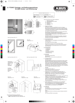
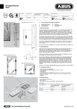
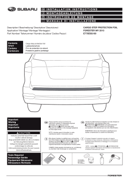
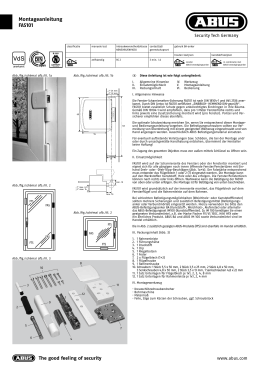
D Montage- und Bedienungsanleitung für ABUS Fenster-Universalschloss FTS 96
G ABUS Installation and operation instructions for ABUS universal window lock FTS 96
Abb. /fig.
schéma
afb. /ill. 1
D
I.
II.
III.
120
Fensterflügel
Window
Battant de fenêtre
Raam
Battente
51
Fensterrahmen
Frame
Cadre
Kozijn
Telaio
3 18
max. 29
28
51
Abb./fig.
schéma
afb./ill. 2
FTS
FAS
FAS
FTS
FTS
1
3
4
I. Allgemeine Hinweise
Das Fenster-Universalschloss FTS 96 ist nach den strengen Prüfanforderungen
der DIN 18 104-1 und VdS 2536 anerkannt. Durch DIN Certco ist FTS 96
zertifiziert „EINBRUCHHEMMEND DIN-geprüft“. FTS 96 bietet zusätzlich
Schutz gegen unberechtigtes Eindringen in ihre Räume. Gemäß DIN 18 104-1
wird empfohlen, dass pro 1 Meter Fensterhöhe rechts und links jeweils eine
Zusatzsicherung montiert wird (pro Fenster). Polizei und Versicherer empfehlen
dieses ebenfalls.
Die optimale Schutzwirkung erreichen Sie, wenn Sie entsprechend dieser
Montage- und Bedienungsanleitung vorgehen.
Die Befestigungsschrauben sollten zur Vermeidung von Überdrehung mit
einem geeigneten Werkzeug eingeschraubt und von Hand angezogen werden.
Ausschließlich ABUS-Befestigungsmaterial einsetzen.
Für eventuell auftretende Verletzungen bzw. Schäden, die bei der Montage
und/oder durch unsachgemäße Handhabung entstehen, übernimmt der
Hersteller keine Haftung!
Ein Zugang des gesamten Objektes muss von außen mittels Schlüssel zu
öffnen sein.
II. Einsatzmöglichkeit
FTS 96 wird auf der Griffseite des Fensters oder der Fenstertür montiert
und eignet sich für alle gängigen nach innen öffnende Fenster/Fenstertüren
mit Dreh- oder -Dreh-Kipp-Beschlägen (Abb. 1). Die Montage kann auf den
Werkstoffen Kunststoff, Holz oder Alu erfolgen. Die Fenster/Fenstertüren
können nach rechts oder links öffnen.
FTS 96 wird grundsätzlich auf der Innenseite montiert, der Schlosskasten auf
dem Fensterflügel und der Schließkasten auf dem Rahmen.
Bei schlechten Befestigungsmöglichkeiten (Weichholz- oder Kunststofffenster)
sollten mehrere Sicherungen und zusätzlich Befestigungsmittel (Befestigungsanker oder Verbundmörtel) eingesetzt werden. Hierzu verwenden Sie
bitte den ABUS-Befestigungsanker BA (Kunststoff-, Weichholz-, Alufenster)
oder alternativ das ABUS-Befestigungsset IM 100 (Kunststofffenster).
Zu IM 100 benötigen Sie einen geeigneten Verbundmörtel,
z.B. der Marke Fischer FIS VS 150C, Hilti HFX oder ein ähnliches Produkt.
ABUS BA und ABUS IM 100 sowie Verbundmörtel sind im Handel erhältlich.
Die in Abb. 2 zusätzlich gezeigten ABUS-Produkte (FAS) sind ebenfalls im
Handel erhältlich.
FAS
FTS
Diese Anleitung ist wie folgt untergliedert:
Allgemeine Hinweise
IV. Werkzeug
Einsatzmöglichkeit
V. Montageanleitung
Packungsinhalt
VI. Bedienung
III.
1.
2.
3.
4.
5.
6.
7.
8.
7
2
5
Packungsinhalt (Abb. 3)
1 Schlosskasten
1 Schließkasten
1 Anschraubleiste
1 Abdeckhaube Schlosskasten
1 Abdeckhaube Schließkasten
2 Unterlegscheiben keilförmig
1 Satz Unterlagen für Rahmenleiste je 1x1, 2, 4, 5 mm
Schrauben:
8 Stück 5,5 x 60 mm
1 Stück M6 x 35 mm
2 Stück 4,2 x 16 mm
3 Stück M6 x 25 mm
2 Stück 4,2 x 9,5 mm
IV. Montagewerkzeug
Kreuzschlitzschraubendreher
Schlitzschraubendreher
Bohrmaschine
Feile, Säge zum Kürzen der Schrauben, ggf. Schraubstock
1 Inbusschlüssel SW 4
Bohrtabelle
8
Abb./fig./schéma /afb./ill. 3
6
G
I.
II.
III.
These instructions are organised in the following sections:
General instructions
IV. Tools
Possible uses
V. Installation instructions
Pack contents
VI. Operation
I. General instructions
The universal window lock FTS 96 is recognised as complying with the
strict test requirements of DIN 18 104-1 and VdS 2536.
FTS 96 is certified by DIN Certco as “BURGLAR RETARDANT DIN tested”.
FTS 96 offers additional protection from unauthorised intruders in your rooms.
DIN 18 104-1 recommends that an additional security device should be
fitted on the left and right for every meter in height (per window).
The police and insurance companies also give the same recommendation.
Optimum protection can be achieved by proceeding according to these
installation and operation instructions. To prevent the risk of overtightening,
the fastening screws should by screwed in using a suitable tool and tightened
by hand. Only use ABUS fastening material.
The manufacturer does not assume any liability for possible injuries
or damages caused during installation and/or by incorrect handling!
II. Application
FTS 96 is mounted on the handle side of the window or French door
and is suitable for all common windows/French doors openingto the
inside with turn or turn-and-tilt hardware (fig. 1).
The lock can be fitted to wood, PVC or aluminium.
The windows/French doors can open to the right or left.
FTS 96 is always fitted on the inside, with the lock case on the casement
and the striking plate on the frame.
In poor fixture conditions (soft or hollow or foam base and PVC windows
with and without metal inlay and wooden windows) and/or good possibilities
for intrusion from the outside, more security devices and additional fastenings
should be used (composite mortar or fixing bolts). If the frame itself is too
weak for sensible retrofitting, it may be necessary for example to reinforce the
frame.
To do so, please use the ABUS fixing bolt BA or alternatively for PVC frames,
the ABUS fastening set IM 100. For IM 100 you need a suitable composite
mortar, e.g. Fischer FIS VS 150C or similar. ABUS BA and ABUS IM 100 are
available from retail stores together with composite mortar.
The ABUS products (FAS) shown in fig. 2 are also available from retail
stores.
III.
1.
2.
3.
4.
5.
6.
7.
8.
Pack contents (fig. 3)
1 lock case
1 striking plate
1 screw-on strip
1 cover cap for lock case
1 cover cap for locking case
2 wedge-shaped washers
1 set of spacers for the frame strip 1x 1, 2, 4, 5 mm each
Screws:
8 each 5.5 x 60 mm
2 each 4.2 x 16 mm
2 each 4.2 x 9,5 mm
1 each M6 x 35 mm
3 each M6 x 25 mm
IV. Installation tools
Phillips screwdriver
Slotted recess screwdriver
Drill
Saw, file for shortening the screws, possibly vice
1 hex key, width across flats 4
Drilling table
für
Schrauben
Ø
In Holz und Kunststoff
ohne Metalleinlage
Bohrer Ø
In Alu und Kunststoff
mit Metalleinlage
Bohrer Ø
for
screws
Ø
in wood and PVC
without metal inlay
drill bit Ø
in aluminium and PVC
with metal inlay
drill bit Ø
5,5 mm
4 mm
4,5 mm
5.5 mm
4 mm
4.5 mm
4,2 mm
3 mm
3 mm
4.2 mm
3 mm
3 mm
F Instructions de montage pour serrure de fenêtre universelle ABUS FTS 96
n Montage- en gebruiksaanwijzing voor ABUS universeel bijzetslot FTS 96
I Istruzioni di montaggio ed uso della serratura universale per finestre ABUS FTS 96
F Ce manuel comporte les chapitres suivants:
I. Conseils d’ordre général
II. Application
III. Liste de colisage
IV. Outillage
V. Instructions de montage
VI. Utilisation
I. Conseils d’ordre général
La serrure de fenêtre universelle FTS 96 satisfait aux exigences de contrôle
sévères des normes DIN 18 104-1 et VdS 2536. Le certificat DIN indique que
FTS 96 a obtenu la qualification «anti-effraction DIN». FTS 96 offre en plus
une protection contre les intrusions par effraction dans votre logement.
Selon la norme DIN 18 104-1, il est recommandé de monter une sécurité
complémentaire par mètre de hauteur de fenêtre, à gauche comme à droite
(par fenêtre). La police et les compagnies d’assurance le recommandent
également.
Pour un effet de protection optimal, suivez les instructions de ce manuel
d’installation et d’utilisation. Afin d’éviter un serrage abusif, vissez et serrez
les vis de fixation à la main et avec un outillage adéquat. Utilisez exclusivement des accessoires ABUS.
Le fabricant n’assume aucune responsabilité pour d’éventuels blessures
ou dégâts causés pendant l’installation et/ou par suite de manipulations
inappropriées!
L’ensemble doit être accessible de l’extérieur afin de l’ouvrir au moyen
d’une clé.
II. Application
FTS 96 est monté du côté de la poignée de la fenêtre ou de la porte-fenêtre
et convient pour toutes les fenêtres/portes-fenêtres courantes, ouvrant vers
l’intérieur et pourvues de quincaillerie battante ou oscillo-battante (schéma 1).
L’installation peut être effectuée sur des châssis en bois, en PVC ou en
aluminium. Les fenêtres/portes-fenêtres peuvent s’ouvrir à gauche ou à droite.
FTS 96 est monté en principe du côté intérieur, la gâche sur l’ouvrant et
la serrure sur le dormant.
En cas de possibilités de fixation défavorables (fenêtres en bois ou en PVC),
plusieurs sécurités et des fixations supplémentaires (plots d’ancrage ou
mortier) doivent être prévues.
Pour cela, utilisez l’ancre de fixation ABUS BA (pour fenêtres en PVC,
en bois tendre ou en aluminium) ou l’ensemble de fixation ABUS IM 100
(pour fenêtres en PVC). Pour IM 100, un mortier approprié est requis, par
exemple FIS VS 150C de la marque Fischer, HFX de la marque Hilti ou un
produit similaire. ABUS BA et ABUS IM 100 ainsi que le mortier de fixation
sont disponibles dans le commerce.
Les produits ABUS complémentaires illustrés en schéma 2 (FAS) sont
également disponibles dans le commerce.
III.
1.
2.
3.
4.
5.
6.
7.
8.
Liste de colisage (schéma 3)
1 boîtier
1 gâche
1 platine de fixation
1 cache pour boîtier
1 cache pour gâche
2 entretoises coniques
1 ensemble d’entretoises pour dormant chacun 1x1, 2, 4, 5 mm
Vis:
8 pièces 5,5 x 60 mm
1 pièces M6 x 35 mm
2 pièces 4,2 x 16 mm
3 pièces M6 x 25 mm
2 pièces 4,2 x 9,5 mm
IV. Outillage de montage
Tournevis cruciforme
Tournevis plat
Perceuse
Lime, scie pour raccourcir les vis, tournevis
1 clé à six-pans SW 4
n
I.
II.
III.
Deze montage- en gebruiksaanwijzing is als volgt onderverdeeld:
Algemeen
IV. Gereedschap
Toepassingsmogelijkheden
V. Montage-instructies
Verpakkingsinhoud
VI. Gebruik
I. Algemeen
Bijzetgrendel voor naar binnen draaiende draai/kiep elementen.
FTS 96 is volgens keuringseisen NEN 5096 SKG gecertificeerd.
De FTS 96 biedt daarnaast bescherming tegen onbevoegd binnendringen
van uw woning. Advies: monteer aan de sluitzijde voor maximale veiligheid
2 stuks per 1 meter raamhoogte. Op kunststof zonder metalen kern dient
u dit slot in combinatie met ABUS BA bevestigingsanker te monteren.
Optioneel verkrijgbaar, zie voor montage in de handleiding van BA.
Optimale veiligheid wordt bereikt door nauwkeurig opvolgen van deze
montage- en gebruiksaanwijzing. Om overexpansie of doldraaien van de
bevestigingsschroeven te vermijden, draait u handmatig en met passend
gereedschap de schroeven vast.
Voor eventueel verwondingen en/of schade tijdens montage en/of
door ondeskundig gebruik ontstaan, aanvaardt de fabrikant geen
aansprakelijkheid!
II. Toepassingsmogelijkheden
De FTS 96 wordt aan de sluitzijde van het raam of deur gemonteerd en
is geschikt voor alle gangbare naar binnen draaiende ramen en deuren
met draai(/kiep)-beslag (afb. 1). De montage kan op de materialen hout,
kunststof of aluminium worden uitgevoerd. De ramen/deuren kunnen naar
rechts of links opengaan.
FTS 96 wordt principe uitsluitend ann de binnenkant gemonteerd;
de slotkast op het raam of de deur en de sluitkast op het kozijn.
Bij slechte bevestigingsmogelijkheden (zacht hout of kunststof) dienen
meerdere beveiligingen en extra beveiligingsmaterialen te worden toegepast.
Hiervoor kunt u het ABUS-bevestigingsanker BA (zacht hout, kunststof,
aluminium) of de ABUS-bevestigingsset IM 100 (kunststof) gebruiken.
Voor de IM 100 heeft u een geschikt chemisch anker, bijv. Fischer FIS VS 150C,
Hilti HFX of vergelijkbaar. ABUS BA, ABUS IM 100 en chemische ankers zijn
in de handel verkrijgbaar.
De in afb. 2 weergegeven ABUS-producten (FAS) zijn ook in de handel
verkrijgbaar.
III.
1.
2.
3.
4.
5.
6.
7.
8.
Verpakkingsinhoud (afb. 3)
1 slotkast
1 sluitkast
1 montageplaat
1 afdekkap slotkast
1 afdekkap sluitkast
2 wigvormige opvulringen
1 set opvulplaatjes 1x1, 2, 4, 8 mm (elk 1 stuk)
Schroeven/bouten:
8 stuks 5,5 x 60 mm
2 stuks 4,2 x 16 mm
2 stuks 4,2 x 9,5 mm
1 stuks M6 x 35 mm
3 stuks M6 x 25 mm
IV. Montagegereedschap
Kruiskopschroevendraaier
Sleufschroevendraaier
Boormachine
Vijl, zaag voor het inkorten van de schroeven, evt. bankschroef
1 inbussleutel 4 mm
Boortabel
Tableau de perçage
I
I.
II.
III.
Queste istruzioni si suddividono nel modo seguente:
Istruzioni generali
IV. Attrezzi
Possibilità d´impiego
V. Istruzioni di montaggio
Contenuto della confezione
VI. Uso
I. Istruzioni generali
La sicura per cerniere di finestre FTS 96 è conforme ai severi requisiti
di controllo della DIN 18 104-1 e della VdS 2536.
Con la DIN Certco essa è certificata come «ANTISCASSO conf. DIN».
La FTS 96 garantisce una protezione in più a difesa della Vostra casa.
Secondo DIN 18 104-1 si consiglia di montare per ogni metro di altezza
della finestra, una sicura supplementare sul lato destro e una sul lato
sinistro (per ogni finestra). Anche la polizia e le compagnie d’assicurazione
consigliano tali misure.
Si può ottenere una protezione ottimale, procedendo secondo queste istruzioni
di montaggio ed uso. Le viti di fissaggio, per evitarne un serraggio eccessivo,
devono essere avvitate con un utensile adatto e poi serrate a mano.
Impiegare esclusivamente materiale di fissaggio ABUS.
Per eventuali ferimenti e/o danni, che si verificano durante il montaggio e/o
per maneggio indebito, il produttore non si assume alcuna responsabilità!
II. Possibilità d’impiego
La FTS 96 viene montata sul lato della cerniera della finestra o della portafinestra ed è adatta per tutte le normali finestre e porte-finestre che si
aprono verso l’interno, con ferramenti girevoli o girevoli- a bilico (ill. 1).
Si può montare la FTS 96 su legno, plastica o alluminio.
Le finestre/porte-finestre possono aprirsi verso destra o verso sinistra.
Di solito la FTS 96 viene montata all’interno, la lamiera del battente
sul battente della finestra ed il listello del telaio sul telaio.
Se le possibilità di fissaggio sono scadenti (sottofondo morbido o vuoto
o riempito con espanso e finestre in plastica con o senza inserto metallico
e finestre in legno) e le possibilità di effrazione dall’esterno sono buone,
si dovrebbero utilizzare più sicure e mezzi di fissaggio supplementari
(malta o avvitamento passante o bullone di fissaggio).
Se i telai stessi sono troppo deboli, per poterli allestire adeguatamente
in un secondo tempo, potrebbe essere consigliabile rinforzare, per esempio,
i telai stessi.
Allo scopo utilizzare per favore il bullone di fissaggio ABUS BA o come
alternativa, nel caso di telai in plastica, il kit di fissaggio ABUS IM 100.
Per il IM 100 serve una malta adatta, p.e. della marca Fischer FIS VS 150C
o un prodotto simile. ABUS BA e ABUS IM 100 come anche la malta si possono
acquistare.
I prodotti ABUS mostrati inoltre nel’ill. 2 (FAS) sono anche reperibili in
commercio.
III.
1.
2.
3.
4.
5.
6.
7.
8.
Contenuto della confezione (ill. 3)
1 scatola della serratura
1 cassa della serratura
1 listello da avvitare
1 coperchietto della scatola della serratura
1 coperchietto della cassa della serratura
2 rondelle cuneiformi
1 kit di spessori per listello del telaio 1x1, 2, 4, 8 mm ciascuno
Viti:
2 viti da 5,5 x 60 mm
1 vite M6 x 35 mm
2 viti da 4,2 x 16 mm
3 viti M6 x 25 mm
2 viti da 4,2 x 9,5 mm
IV. Attrezzi da montaggio
cacciavite a croce
cacciavite per viti a testa intagliata
tarpano
lima, sega per accorciare le viti, in caso morsa
1 chiave ad esagono incassato SW 4
Tabella di trapanazioni
pour
vis
de Ø
dans châssis bois et PVC
sans armature métallique
foret Ø
dans châssis aluminium et PVC
avec armature métallique
foret Ø
voor
schroeven
Ø
in hout en kunststof
zonder metalen kern
boor Ø
in aluminium en kunststof
met metalen kern
boor Ø
per
viti
Ø
in legno e plastica
senza inserto metallico
punta da trapano Ø
in alluminio e plastica
con inserto metallico
punta da trapano Ø
5,5 mm
4 mm
4,5 mm
5,5 mm
4 mm
4,5 mm
5,5 mm
4 mm
4,5 mm
4,2 mm
3 mm
3 mm
4,2 mm
3 mm
3 mm
4,2 mm
3 mm
3 mm
Falzhöhe
Rebate height
Recouvrement
Opdekmaat
Altezza
d’incassatura
0 – 29 mm
Schließkasten
Locking case
Gâche
Sluitkast
Scatola della
serratura
3 mm
Rahmen
Frame
Cadre
Kozijn
Telaio
Abb./fig.
schéma
afb./ill. 5
D V. Montageanleitung:
Unterlagen für Höhenausgleich
Spacers
Entretoises
Opvulplaatjes
Spessori da livellamento
Abb. /fig.
schéma
afb. /ill. 6
2 mm
1.
Tür bzw. Fenster
Door/Window
Fenêtre
Deur/Raam
Porta risp. Finestra
2.
3.
4.
Abb./fig.
schéma
afb./ill. 8
2 mm
3 mm
1.
A
C
2.
B
3.
4.
B
5.
6.
C
A
7.
Montage:
Montage des Schlosskastens:
Abdeckhaube (4) vom Schlosskasten (1) durch Druck auf Rastpunkte
von unten entfernen (s. Abb. 5). Riegel ausschließen.
Schlosskasten (1) in gewünschter Position auf Fensterflügel bzw.
Türblatt anhalten, Abstand zur Kante 2 mm (s. Abb. 6).
Bohrposition A und B (nur bei Kunststofffenstern und -türen zusätzlich C)
anzeichnen und vorbohren (s. Abb. 7 und Bohrtabelle).
Schlosskasten (1) anschrauben. Bohrungen A (je nach Falzhöhe)
Schrauben 4,2 x 16 mm oder 4,2 x 9,5 mm (Schraubendreher mit
Magnetspitze verwenden). Bohrungen B (C) Schrauben 5,5 x 60 mm.
Montage des Schließkastens:
Schlosskasten (1) und Schließkasten (2) müssen auf gleicher Ebene
liegen (s. Abb. 4). Zum Ausgleich der unterschiedlichen Falzhöhen wird
der Schließkasten (2) unterlegt. Hierzu dienen die Anschraubleiste (3)
und/oder die Unterlagen (7).
Falzhöhe: ab 14 mm [mit Anschraubleiste (3) und ggf. Unterlagen (7)].
Anschraubleiste (3) (14 mm hoch) mittig auf gleiche Höhe und im parallelen Abstand von 3 mm zum Schlosskasten (1) anhalten (s. Abb. 8).
Auf richtige Lage der Anschraubleiste (3) achten (s. Abb. 8 und 9).
Bohrpositionen C1 und C2 anzeichnen und vorbohren (s. Abb. 9 und
Bohrtabelle).
Anschraubleiste (3) bei Bedarf (Falzhöhe größer 14 mm) mit Unterlagen
(7) unterfüttern. Mit Schrauben 5,5 x 60 mm festschrauben.
Durch die schrägen Schraubenlöcher D im gleichen Winkel zur Wand hin
schräg vorbohren (s. Bohrtabelle). Wenn dieses nicht möglich ist, so kann
auch senkrecht gebohrt werden. Dann in Bohrungen D die beiden keilförmigen Unterlegscheiben (6) einlegen.
In Bohrungen D2 weitere Schrauben 5,5 x 60 mm einschrauben.
Abdeckhaube (5) vom Schließkasten (2) durch Druck auf Rastpunkte
von unten entfernen (s. Abb. 10).
Schließkasten (2) mit 3 Schrauben M6 x 25 mm auf die Anschraubleiste
(3) schrauben.
Funktion prüfen:
Riegel müssen beim Einschließen in den Schließkasten (2) frei laufen.
Abb./fig.
schéma
afb./ill. 9
Abb. /fig.
schéma
afb. /ill. 10
Abb. /fig.
schéma
afb. /ill. 11
Abb./fig.
schéma
afb./ill. 12
8. Beide Abdeckhauben aufdrücken.
3 mm
E2
D
C1
E1
Falzhöhe: 0 bis 13 mm (ggf. mit Unterlagen).
1. Abdeckhaube (5) vom Schließkasten (2) durch Druck auf Rastpunkte
von unten entfernen (s. Abb. 10).
2. Schließkasten (2) mittig auf gleicher Höhe und im parallelen Abstand
von 3 mm vom Schlosskasten (1) anhalten (s. Abb. 11).
3. Bohrposition E1 bis E3 anzeichnen (s. Abb. 12) und vorbohren
(s. Bohrtabelle).
4. Schließkasten (2) bei Bedarf mit Unterlagen (7) unterfüttern und mit
3 Schrauben 5,5 x 60 mm festschrauben.
Funktion prüfen:
Riegel müssen beim Einschließen in den Schließkasten (2) frei laufen.
D
C2
E3
5. Beide Abdeckhauben aufdrücken.
VI. Bedienung
FTS 96 lässt sich ohne Schlüssel durch Drehen des Knopfes
verschließen. Zum Öffnen wird der Schlüssel benutzt.
ABUS - Das gute Gefühl der Sicherheit
D Technische Änderungen vorbehalten. Für Irrtümer und Druckfehler keine Haftung. ABUS © 2006
G Subject to technical alterations. No liability for mistakes and printing errors. ABUS © 2006
• Before installation, please check the setting of the window
or French door.
• If necessary, readjust the fittings so that the window (French door)
opens and closes perfectly.
• Also check whether your window/French door complies with the
minimum dimensions shown in fig. 1.
• The depths of the drilled holes and screw lengths must be adjusted
to the local conditions.
• Avoid the drill or screws from coming out at the back!
Possibly work with drill stopper or shorten the existing screws.
• When drilling, do not damage any moving parts, seals or glass panes.
Wichtige Hinweise:
1. Vor der Montage prüfen Sie bitte die Einstellung des Fensters bzw.
der Fenstertür. Stellen Sie sicher, dass sich das Fenster/die Fenstertür
einwandfrei öffnen und schließen lässt.
2. Messen Sie auch nach, ob die in Abb. 1 angegebenen Mindestmaße
an Ihrem Fenster/Ihrer Fenstertür vorhanden sind.
3. Die Bohrlochtiefen bzw. die Schraubenlängen müssen auf die
örtlichen Gegebenheiten abgestimmt werden.
4. Austreten des Bohrers bzw. der Schrauben auf der Rückseite
vermeiden! Ggf. mit Bohranschlag arbeiten oder die vorhandenen
Schrauben kürzen. Beim Bohren keine beweglichen Teile, Dichtungen
oder Glasscheiben verletzen.
Schlosskasten
Lock case
Boîtier
Slotkast
Cassa della serratura
Abb. /fig.
schéma
afb. /ill. 7
G V. Installation instructions:
1.
2.
3.
4.
1.
2.
3.
4.
5.
6.
7.
Installation:
Fitting the lock case:
Remove the cover cap (4) from the lock case (1) from below by pressing
on the catch points (see fig. 5). Undo the locking bolt.
Hold the lock case (1) in the required position against the window
casement or door, at a distance of 2 mm to the edge (see fig. 6).
Mark and pre-drill hole position A and B (for PVC windows and doors
also C) (see fig. 7 and drilling table).
Screw on lock case (1). For holes A (depending on rebate height),
use screws 4.2 x 16 mm or 4.2 x 9.5 mm (screwdriver with magnetic tip).
Holes B (C) screws 5.5 x 60 mm.
Fitting the striking plate:
The lock case (1) and striking plate (2) must be on the same level
(see fig. 4). To compensate for the differing rebate heights,
the striking plate (2) is lined, using the screw-on strip (3) and/or the
spacers (7).
Rebate height: from 14 mm [with screw-on strip (3) and possibly
shims (7)].
Hold the screw-on strip (14 mm high) on the same level and at a parallel
distance of 3 mm to the lock case (1) (see fig. 8). Ensure that the screw-on
strip (3) is in the right position (see fig. 8 and 9).
Mark and pre-drill bore holes C1 and C2 (see fig. 9 and drilling table).
Line screw-on strip (3) with spacers (7) if necessary (rebate height larger
than 14 mm). Screw tight with screws 5.5 x 60 mm.
Drill in the middle through the slanting screw holes D at the same
angle to the wall (see drilling table). If this is not possible, drill vertically.
Then place the two wedge-shaped washers (6) in holes D.
Screw 2 more screws 5.5 x 60 mm into holes D.
Remove the cover cap (5) from the striking plate (2) from below by
pressing on the catch points (see fig. 10).
Screw striking plate (2) to screw-on strip with 3 screws M6 x 25 mm.
Check function:
Locking bolt must run freely into the striking plate (2) when closing.
8. Press on both cover caps.
Rebate height: 0 to 13 mm (possibly with shims).
1. Remove the cover cap (5) from the striking plate (2) from below
by pressing on the catch points (see fig. 10).
2. Hold striking plate (2) centrally on the same level and at a parallel
distance of 3 mm to the lock case (1) (see fig. 11).
3. Mark and pre-drill holes position E1 to E3 (see fig. 12)
(see drilling table).
4. Line striking plate (2) with spacers (7) if necessary and screw tight with
3 screws 5.5 x 60 mm.
Check function:
Locking bolt must run freely into the striking plate (2) when closing.
5. Press on both cover caps.
VI. Operation
FTS 96 can be locked without a key by turning the knob.
Open with the key.
www.abus.com
390104 5/06
Abb./fig./schéma /afb./ill. 4
Indications importantes:
1. Avant l’installation, contrôlez le réglage de la fenêtre ou de la
porte-fenêtre. Assurez-vous que la fenêtre/porte-fenêtre ouvre et
ferme parfaitement.
2. Vérifiez si votre fenêtre/porte-fenêtre comporte les dimensions
minimales indiquées en schéma 1.
3. Les profondeurs de perçage ou les longueurs de vis doivent être
adaptées aux conditions locales.
4. Evitez le dépassement de perçage ou de vis sur la face arrière!
Utilisez le cas échéant une butée de perçage ou raccourcissez les
vis de fixation. Lors du perçage, évitez d’endommager les éléments
mobiles, les joints ou les vitres.
1.
2.
3.
4.
1.
2.
3.
4.
5.
6.
7.
Montage du boîtier:
Déposez le cache du boîtier (1) par le bas en appuyant sur des points
d’appui (voir schéma 5). Déverrouillez les pênes.
Maintenez le boîtier (1) dans la position désirée sur le vantail ou sur
l’encadrement la fenêtre. Distance du bord 2 mm (voir schéma 6).
Tracez et préforez les fixations de vis A et B (et C, uniquement sur des
fenêtres et portes-fenêtres en PVC) (voir schéma 7 et tableau de perçage).
Fixez le boîtier (1). Fixations de vis A: (en fonction de la hauteur
de rainure) vis de 4,2 x 16 mm ou de 4,2 x 9,5 mm (utilisez un tournevis
à tête aimantée). Fixations de vis B (C ): vis de 5,5 x 60 mm.
Montage de la gâche:
Le boîtier (1) et la gâche (2) doivent se trouver à la même hauteur
(voir schéma 4). Pour égaliser les différentes hauteurs du recouvrement
la gâche (2) doit être rehaussé. C’est à cela que servent la platine
de fixation (3) et/ou les entretoises (7).
Recouvrement: supérieure à 14 mm [avec platine de fixation (3) et
éventuellement des entretoises (7)].
Maintenez la platine de fixation (3) (d’une hauteur de 14 mm) centrée,
à la même hauteur et à une même distance de 3 mm en parallèle au
boîtier (1) (voir schéma 8). Assurez-vous de la bonne position de la
platine de fixation (3) (voir schéma 8 et 9).
Tracez et préforez les fixations de vis C1 et C2 (voir schéma 9 et tableau
de perçage).
Rehaussez selon les besoins (profondeur de rainure supérieure à 14 mm)
la platine de fixation (3) au moyen des entretoises (7). Fixez-la avec des
vis de 5,5 x 60 mm.
Préforez de biais dans le même angle et au travers des fixations de vis D
dans la paroi (voir tableau de perçage). Si cela s’avère impossible,
forez dans le sens perpendiculaire. Dans ce cas, posez les entretoises
coniques (6) dans les trous de fixation D.
Installez d’autres vis de 5,5 x 60 mm dans les fixations D2.
Déposez le cache (5) de la gâche (2) par le bas en appuyant sur les points
d’appui (voir schéma 10).
Fixez la gâche (2) sur la platine de fixation (3) avec 3 vis M6 x 25 mm.
Contrôlez le bon fonctionnement: Lors de la fermeture,
les pênes doivent coulisser librement dans le boîtier de gâche (2).
8. Clipsez les deux caches.
Recouvrement: 0 –13 mm (éventuellement avec entretoises)
1. Déposez le cache (5) de la gâche (2) par le bas en appuyant sur des
points d’appui (voir schéma 9).
2. Maintenez la platine de fixation (2) centrée, à la même hauteur et à une
même distance de 3 mm en parallèle au boîtier (1) (voir schéma 11).
3. Tracez les fixations de vis E1 à E3 (voir schéma 12) et préforez
(voir tableau de perçage).
4. Ajustez la hauteur de la gâche (2) selon les besoins avec des
entretoises (7) et fixez-le avec 3 vis de 5,5 x 60 mm.
Contrôlez le bon fonctionnement: Lors de la fermeture,
les pênes doivent coulisser librement dans la gâche (2).
5. Clipsez les deux caches.
n V. Montage-instructies:
Belangrijke opmerkingen:
• Voor de montage dient u de afstelling van het raam resp. deur
te controleren. Stel evt. het beslag opnieuw in, zodat het correct
functioneert.
• Meet ook na of de in afb. 1 aangegeven minimum afmetingen
daadwerkelijk op uw raam/deur beschikbaar zijn.
• De boordieptes en schroeflengtes moeten aan het gevelelement
aangepast worden.
• Voorkom doorboren en/of -schroeven. Evt. met een booraanslag
werken, kortere schroeven kopen of inkorten. Bij het boren geen
bewegende delen, afdichtingen of glas beschadigen.
Montage van de slotkast:
1. De afdekkap (4) van de slotkast (1) door druk op de vergrendelingspunten
van onder af verwijderen (zie afb. 5). Schoten uit de slotkast draaien.
2. Slotkast (1) op de gewenste positie op het raam/de deur plaatsen.
Afstand t.o.v. de raamkant resp. deurkant 2 mm (zie afb. 6).
3. Boorpositie A en B (bij kunststof ook C) aftekenen en voorboren
(zie afb. 7 en boortabel).
4. Slotkast (1) monteren. Boorgaten A (afhankelijk van de opdekmaat)
met schroeven 4,2 x 16 mm of 4,2 x 9,5 mm (schroevendraaier met
magneetpunt gebruiken) / boorgaten B (C) met schroeven 5,5 x 60 mm.
Montage van de sluitkast:
Slotkast (1) en sluitpkast (2) moeten op hezelfde niveau liggen
(zie afb. 4). Ter compensatie van de verschillende opdekmaten wordt
de sluitkast (2) opgevuld. Hiervoor dient de montageplaat (3) en evt.
opvulplaatjes (7).
Opdekmaat > 14 mm
1. Montageplaat (3) (14 mm) in het midden op dezelfde hoogte en op
3 mm afstand evenwijdig aan de slotkast (1) tegen het kozijn plaatsen
(zie afb. 8). Op de juiste positie van de montageplaat (3) letten
(zie afb. 8 en 9).
2. Boorgaten C1 en C2 aftekenen en voorboren (zie afb. 9 en boortabel).
3. Montageplaat (3) indien nodig (opdekmaat > 14 mm) met opvulplaatjes
(7) uitvullen en m.b.v. de schroeven 5,5 x 60 mm monteren.
4. De schuine schroefgaten D in dezelfde hoek voorboren (zie boortabel).
Wanneer een schuine schroefverbinding niet mogelijk is,
kan m.b.v. de wigvormige opvulringen (6) in de schroefgaten D ook
recht worden geschroefd.
5. In de boorgaten D2 nog meer schroeven 5,5 x 60 mm monteren.
6. Afdekkap (5) van de sluitplaat (2) door druk op de vergrendelingspunten van onder af verwijderen (zie afb. 10).
7. Sluitplaat (2) m.b.v. 3 bouten M6 x 25 mm op de montageplaat
monteren (3).
Werking controleren:
De schoten moeten bij het vergendelen vrij in de sluitplaat (2) lopen.
8. Afdekkappen op de slot- en sluitkast drukken.
Opdekmaat 0 tot 13 mm
1. Afdekkap (5) van de sluitkast (2) door druk op de vergrendelingspunten
van onder af verwijderen (zie afb. 10).
2. Sluitplaat (2) in het midden op dezelfde hoogte en op 3 mm afstand
evenwijdig aan de slotkast (1) tegen het kozijn (zie afb. 11).
3. Boorpositie E1 tot E3 aftekenen (zie afb. 12) en voorboren (zie boortabel).
4. Sluitkast (2) indien nodig met opvulplaatjes (7) uitvullen en m.b.v.
3 schroeven 5,5 x 60 mm monteren.
Werking controleren:
De schoten moeten bij het vergendelen vrij in de sluitplaat (2) lopen.
5. Afdekkappen op de slot- en sluitkast drukken.
VI. Gebruik
FTS 96 kan zonder sleutel m.b.v. de draaiknop vergrendeld worden.
Voor het ontgrendelen is de sleutel nodig.
VI. Utilisation: La fermeture de FTS 96 s’effectue sans clé,
en tournant le bouton. Pour l’ouverture, la clé est requise.
I V. Istruzioni per il montaggio:
Avvertenze importanti:
• Prima del montaggio verificare per favore la regolazione della
finestra risp. della porta finestra.
• Se necessario registrare nuovamente i ferramenti affinché la
finestra (la porta-finestra) si chiuda e si apra perfettamente.
• Verificare anche che le misure minime indicate nell’ill. 1 esistano
nelle vostre finestre/ porte-finestre.
• Le profondità per trapanare i fori, risp. le lunghezze delle viti
devono essere adattate alle condizioni particolari.
• Evitare che la punta del trapano risp. la vite fuoriesca dall’altra
parte!
Se necessario lavorare con arresto del trapano o accorciare le viti.
• Quando si trapana, non danneggiare parti mobili, guarnizioni
o vetri.
Montaggio:
Montaggio della scatola della serratura:
1. Togliere il coperchietto (4) dalla scatola della serratura (1) premendo
sui punti di incastro dal basso (vedi ill. 5). Aprire il chiavistello.
2. Tenere la scatola della serratura (1) nella posizione desiderata sul
battente della finestra risp. della porta, distanza dal bordo 2 mm
(vedi ill. 6).
3. Disegnare fori di trapanazione A e B (con finestre e porte in plastica
anche C) e trapanare (vedi ill. 7 e tabella trapanazioni).
4. Avvitare la scatola della serratura (1). Fori A (secondo altezza d’incastro)
viti 4,2 x 16 mm o 4,2 x 9,5 mm (usare cacciavite con punta magnetica).
Fori B (C) viti 5,5 x 60 mm.
Montaggio della cassa della serratura:
Scatola della serratura (1) e cassa della serratura (2) devono stare sullo
stesso livello (vedi ill. 4) Per compensare le diverse altezze di incastro,
sotto la cassa della serratura (2) si mettono spessori.
Allo scopo si utilizzano il listello da avvitare (3) e/o gli spessori (7).
Altezza d’incassatura: a partire da 14 mm
[con listello da avvitare (3) e in caso spessori (7)].
1. Avvitare il listello (3) (alto 14 mm) centrato alla stessa altezza e tenere a
distanza parallela di 3 mm rispetto alla scatola della serratura (1)
(vedi ill. 8). Fare attenzione alla giusta posizione del listello da avvitare (3)
(vedi ill. 8 e 9).
2. Disegnare le posizioni da trapanare C1 e C2 (vedi ill. 9 e tabella
trapanazioni).
3. Se necessario (altezza d’incastro superiore a 14 mm) mettere sotto
il listello da avvitare degli spessori (7). Avvitare saldamente con
viti 5,5 x 60 mm.
4. Trapanare attraverso i fori obliqui per le viti D con la stessa angolatura,
obliquamente rispetto alla parete (vedi tabella trapanazioni).
Se non fosse possibile, si può trapanare anche perpendicolarmente.
Poi mettere nei fori D le due rondelle a cuneo (6).
5. Nei fori D2 avvitare altre viti 5,5 x 60 mm.
6. Rimuovere il coperchietto (5) dalla cassa della serratura (2) premendo sui
punti di incastro dal basso (vedi ill. 10).
7. Avvitare la cassa della serratura (2) con 3 viti M 6x 25 al listello (3).
Controllare il funzionamento: I chiavistelli devono poter scorrere
liberamente quando si chiudono nella cassa della serratura (2).
8. Applicare premendo i due coperchietti (4 e 5).
Altezza di incastro: da 0 a 13 mm (se necessario con spessori).
1. Rimuovere il coperchietto (5) dalla cassa della serratura (2) premendo sui
punti di incastro dal basso (vedi ill. 10).
2. Tenere la cassa della serratura (2) centrata alla stessa altezza e a distanza
parallela di 3 mm dalla scatola della serratura (1) (vedi ill. 11).
3. Disegnare posizioni di trapanazione da E1 a E3 (vedi ill. 12) e trapanare
(vedi tabella trapanazioni).
4. Se necessario mettere sotto alla cassa della serratura (2) spessori (7)
e avvitare saldamente con 3 viti 5,5 x 60 mm.
Controllare il funzionamento: I chiavistelli devono poter scorrere
liberamente quando si chiudono nella cassa della serratura (2).
5. Applicare premendo i due coperchietti (4 e 5).
VI. Uso
FTS 96 si può chiudere senza chiave, girando il pomello
(in caso impostare il codice). Per aprire, si usa la chiave.
www.abus.com
F Nous nous réservons le droit de toutes modifications techniques. Nous n’assumons aucune responsabilité pour des erreurs ou défauts d’impression éventuels. ABUS © 2006
n Technische wijzigingen voorbehouden. Geen aansprakelijkheid voor vergissingen en drukfouten. ABUS © 2006
I Ci si riservano modifiche tecniche. Per errori e refusi di stampa non ci si assume alcuna responsabilità. ABUS © 2006
390104 5/06
F V. Instructions de montage:
Scaricare