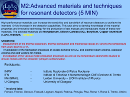
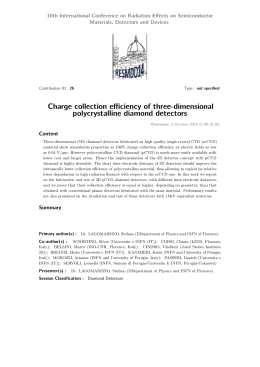
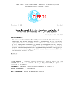
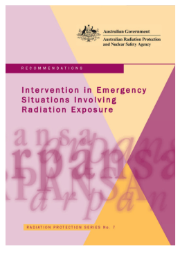
Mem. S.A.It. Suppl. Vol. 11, 178
Memorie della
Supplementi
c SAIt 2007
EXOMARS IRAS (DOSE) radiation
measurements
C. Federico1 , A.M. Di Lellis2 , S. Fonte3 , C. Pauselli1 , G. Reitz4 , and R. Beaujean5
1
2
3
4
5
Dipartimento di Scienze della Terra, Università degli Studi di Perugia, 06100 Perugia Italy
AMDL Srl, Viale Somalia 133, 00199 Roma - Italy
INAF - Istituto di Astrofisca Spaziale e Fisica Cosmologica, via del Fosso del Cavaliere
100, 00133 Roma, Italy; e-mail: [email protected]
German Aerospace Center Institut of Aerospace Medicine, 51147 Koeln - Germany
Universitaet Kiel, IEAP/Extraterrestrik, Leibnizstr. 11-19, 24118 Kiel - Germany
Abstract The characterization and the study of the radiations on their interaction with or-
ganic matter is of great interest in view of the human exploration on Mars. The Ionizing
RAdiation Sensor (IRAS) selected in the frame of the ExoMars/Pasteur ESA mission is
a lightweight particle spectrometer combining various techniques of radiation detection in
space. It characterizes the first time the radiation environment on the Mars surface, and
provide dose and dose equivalent rates as precursor information absolutely necessary to
develop ways to mitigate the radiation risks for future human exploration on Mars. The
Martian radiation levels are much higher than those found on Earth and they are relatively
low for space. Measurements on the surface will show if they are similar or not to those
seen in orbit (modified by the presence of “albedo” neutrons produced in the regolith and
by the thin Martian atmosphere).
IRAS consists of a telescope based on segmented silicon detectors of about 40 mm diameter
and 300 m thickness, a segmented organic scintillator, and of a thermoluminescence
dosimeter. The telescope will continuously monitor temporal variation of the particle count
rate, the dose rate, particle and LET (Linear Energy Transfer) spectra. Tissue equivalent
BC430 scintillator material will be used to measure the neutron dose. Neutrons are selected
by a criteria requiring no signal in the anti-coincidence. Last, the passive thermoluminescence dosimeter, based on LiF:Mg detectors, regardless the on board operation timing, will
measure the total dose accumulated during the exposure period and due to β and γ radiation,
with a responsivity very close to that of a human tissue.
Key words. Thermoluminescence – dosimeter – IRAS – TLD
1. Introduction
The Galactic Cosmic Rays (GCR atomic nuclei, stripped of their electrons) and the Solar
Send offprint requests to: S. Fonte
Particle Events (SPE protons and heavier ions)
are of particular interest for astronauts voyages. Particularly for Mars’s ambient, that is
notable unlike from Earth.
Mars lacks a global magnetic field, GCR
particles arrive isotropically and are more en-
C. Federico, A.M. Di Lellis: EXOMARS IRAS (DOSE)
ergetic than those originating from Solar activity. SPE particles can occur randomly during
the Solar cycle although they tend to occur near
the peaks of Solar activity.
Sun radiates in all wavelengths, from radio
(low energy) to X-rays and γ-rays (highest energy) through visible and infrared; the X-ray
emission is highly variable. X-rays and γ-rays
increase when Sun increases its activity (1-2
orders of magnitude).
There are two kinds of SPE: the Solar Wind
and the Solar Energetic Particle (SEP). The
first ones are charged particles continuously
expelled from the Sun: electrons, protons and
alpha particles (Helium nuclei) with low speed
and low energy. They are carried along solar
magnetic field and modulated by solar cycle
(max at solar max), with an energy of about
1 keV/nucleon.
While the second are charged particles expelled from the Sun at high speed and high
energy, related to extreme events on solar surface. They are sporadic and unpredictable, with
an anisotropic distribution (following magnetic
lines). They tend not to happen at solar min;
their energy is about of 10-100 MeV/nucleon
and it can be greater.
The GCR are charged particles from supernova explosions at very high speed accelerated
by galactic magnetic field; they are composed
of protons (85%), α (12.5%), heavier atoms
(1%) and electrons (1.5%) with an isotropic
distribution. Their intensity are modulated by
solar cycle (∼11 years); Min at solar max.
Their energy is about of 50-500MeV/nucleon
(which means 10sof GeV for heavy ions).
The interplanetary space is unshielded, full
of GCR and solar particles, while near the
Earth, most of solar particles are shielded by
the Earth’s magnetic field, adding effects to
the trapped particles (mostly protons and electrons) in Van Allen belts, from 4000 km to
10000 km in altitude. On the surface, the particles are shielded by atmosphere. On Earth, we
have an average of 2.4 mSv/year, due to space
(17%) and natural radiactivity (83%).
In the Mars Odyssey mission (that is part of
NASA’s Mars Exploration Program), the calculations of MARIE, the Martian Radiation
Environment Experiment for studying the ra-
179
diation environment, estimate about 1 Sv/year
on Mars surface.
Another radiation comes from Mart’s rock.
Martian crust has a bulk composition equivalent to large-ion lithofile (LIL) and heat producing element (K, Th, U) enriched basalt,
with a potassium content of about 0.5% and
Martian Dose Rate = 240 nGy/h (max estimation), see McLennan (2001).
All these radiations interact primary with
the spacecraft structure and after with the astronauts tissues, producing secondary radiations and particles.
The absorption of all this energy by cellular molecules causes several effects (cell death,
molecular breakage and cell genetic mutation)
leading to an increase in the cancer developing
probability.
Every tissue show a different tolerance to
dose. Usually, three organ types are considered: the skin (outside part, unshielded), the
eyes (specially sensitive organs) and the Blood
Forming Organs (BFO, bone marrow): deeper
organs, highly self-shielded.
There is in the ExoMars/Pasteur mission
an instrumentation to estimate the risk of interaction between the radiation and the human’s tissues. It combines a principal sensor: Ionizing RAdiation Sensor (IRAS) and
an optional Thermo Luminescence Detector
with the annexed reader: TLD Reader (formerly named DOSE). IRAS, whose leadership
is German, is the instrument actually selected
for Exomars/Pasteur mission.
2. Ionizing Radiation Sensor (IRAS)
The Ionizing RAdiation Sensor (IRAS) selected in the frame of the ExoMars/Pasteur
ESA mission is a lightweight particle spectrometer combining various techniques of radiation detection in space. Its design from heritage components makes it a powerful experiment to deliver at minimum risk outstanding
scientific data.
It characterizes for the first time the environment radiation on the Mars’s surface, and
provides dose and dose equivalent rates as precursor information absolutely necessary to de-
180
C. Federico, A.M. Di Lellis: EXOMARS IRAS (DOSE)
velop ways to mitigate the radiation risks for
future human exploration on Mars.
The silicon detector telescope sensor of the
instrument uses segmented silicon detectors
and it will continuously monitor temporal variation of the particle count rate, the dose rate,
particle and LET spectra. During operation two
types of measurements will be performed:
estimates the LET value of short range particles stopping inside the detector. In order to
account for the difference in stopping power
of Si and water, the LET(Si)-value is multiplied by a factor of 1.23 to get the LET(H2O)value. This mean conversion factor neglects the
dependence on the particles energy, the uncertainty is estimated to be 3%.
a) single detector mode for dose measurements in the individual detectors;
b) coincidence mode for the measurement of
particle and Linear Energy Transfer (LET)
spectra in the range 2 to 2000 MeV/cm.
Both measurements are an integration over
software defined time periods resulting in a
reasonable data reduction. LET spectra will be
deduced from the energy deposit of coincident
events in the silicon detectors. Since the incidence angle of the particles is not measured,
the energy deposit is converted into LET in silicon, as energy deposit/t, where t is the mean
path length in the detector.
The detector telescope of the IRAS will
work in one mode only. In this mode data
for count and dose rates will be integrated
over pre-selected time intervals, a typical interval may be 10 minutes. These time intervals
are software dependent and can be adjusted
within reasonable counting statistics. Data provided are time resolved count and dose rates
(separate measurement of charged and neutral components) and the measurement of the
LET spectrum. LET values in water from about
2 MeV/cm (minimum ionisation for singly
charged particles) to 2000 MeV/cm are covered.
All data will be stored temporally in an
internal histogram memory. Data need to be
downloaded and transferred to ground. The
maximum data rate is 1 Mb/day.
The coincidence requirement between the
two detector signals of the telescope selects
particles with restricted pathlength in the planar detectors (the angle of the acceptance cone
is about 120◦ ). The LET(Si) values are deduced from the measured energy, deposited in
the individual silicon detectors in coincidence
mode, using a mean pathlength of 364 µmat a
density of 2.33 g/cm3 . This procedure under-
Figure 1. LET spectra for three components: a
GCR particles, solar energetic particles during the
April 15, 2001 event (SEP) and radiation belt particles (SAA).
In Figure 1 shows the measured LET spectra converted to water for the three radiation
fields components which could be separated.
The shape and gradient of the LET spectrum
defines the mean radiation quality factor Q calculated with Q(LET)-values. It is obvious that
the GCR spectrum has the lowest gradient and
thus the highest Q-value.
The IRAS consists of three segmented planar silicon PIN-detectors (300 µm thickness,
outer diameter 42 mm) and a segmented solid
organic scintillator (BC430), with an outer diameter of 50 mm and a thickness of 15 mm.
BC430 is an orange-emitting scintillator that
has a nominal wavelength peak emission near
580 nm. BC430 is conventionally used in radi-
C. Federico, A.M. Di Lellis: EXOMARS IRAS (DOSE)
181
(26 mm diameter, 15 mm height, see Figure
3). The detector telescope sensor is built up by
the inner segments (26 mm diameter) of two
planar silicon detectors. The third Si-detector
is in optical contact with the scintillator and
provides for the light detection.
TLD Reader
(optional)
Survival
Heater
Thermistor
red region, credit Saint-Gobain Crystals
ation detector applications because of its high
light output and because of the high quantum
efficiency of PMTS in this part of the spectrum.
Two additional silicon sensors serve for
measurements of particle count rates and dose
rates in the two remaining directions. Tissue
equivalent BC430 scintillator material will be
used to measure the neutron dose. The scintillator is surrounded by an anticoincidence detector, build up from the telescope and a scintillator ring. Neutrons are selected by a criteria
requiring no signal in the anti-coincidence detectors. The energy spectrum of recoil protons
from neutron interactions will be measured in
the range 1 to 30 MeV.
Lid
Cover Foil
(light tight)
Silicon Detector
(segmented)
Container
BC 430 Detector
(segmented)
Silicon Detector
(segmented)
Power−/Data−
Connector
Circuit Board
Figure 3. The IRAS instrument plan consists of
three segmented planar silicon PIN-detectors and a
segmented solid organic scintillator
The outer segment of the scintillator and
part of the silicon detectors act as anticoincidence shield for the inner part of the scintillator
*)
Solid State Detectors
(Dose, LET)
CSA
Scintillator BC430M
(Neutron detection)
CSA
Anticoincidence
CSA
PC Boards
Trigger Logic
S/H+PHA
Data Processing+Storage
External Interface
H/K Control
Spacecraft
Figure 2. The BC430’s emission spectrum in the
Internal Power Supply Unit
Thermistor
*) Up to 16 Charge Sensitive Amplifier/Shaper Channels
I/F
5V Analog Voltage
70V Detector Voltage
Figure 4. IRAS Electrical design
Two additional PIN diodes are added in
the electronic part beneath the detector head
to provide measurements in x and y direction.
The size of the detector system is 58 mm in
diameter and 55 mm in height, the mass is
about 500 g with a power consumption of
600 mW. The operation of the system is managed by a microcontroller which controls the
operation mode by switching the power and
data lines to the individual sensors via multiplexer on the main board, data sampling, internal intermediate storage and data transfer to
the external main storage. The instrument uses
a RS 422 interface. Similar designs are used
for MATROSHKA sensors and for the detector telescope DOSTEL on EuTEF.
In Figure 4 is rappresented the IRAS electrical design, with an optional insertion of a
TLD Reader.
The IRAS instrument is capable to characterize the radiation field concerning particle
fluences, dose rates and energy transfer spectra
for ionising particles. In addition, it allows to
determine the dose contribution of secondary
neutrons from GCR-interactions with the atmosphere and the soil.
182
C. Federico, A.M. Di Lellis: EXOMARS IRAS (DOSE)
Conduction Band
b
c
EA
T
a
d
EF
R
b
Valence Band
Figure 5. Energy band model showing the electronic transitions in TL material according to a simple two-level model: (a) generation of electrons and
holes; (b) electron and hole trapping; (c) electron release due to thermal stimulation; (d) recombination.
Solid circle are electrons, open circles are holes.
Level T is an electron trap, level R is a recombination centre, E F is Fermi level. See Bos (2001)
The measurement will be carried out on
Mars, during cruise and in orbit. The IRAS
instrument just need to be powered for ten
minutes each hour, during cruise permanent
operation would be prefered. After switch/on
measurements are started automatically. Data
transfer to the DPHU of the rover/GEP shall be
done at the end of the measuring period. The
measuring intervals provide enough information to draw a complete time dependence profile of the radiation environment.
3. The TLD Reader
The TLD Reader is designed to keep track of
the radiation exposure field when the astronauts will pass through during both the surface
stay and during the transit period to and from
the red planet.
The TLD Reader instrument is a passive
dosimeter working without any powering or
support after the annealing. It will not suffer
for any gap during measurements and will collect energy even in presence of huge SPE.
The TLD Reader will only measure the integrated energy over some period of time (dif-
ferent phases of the cruise and of the surface
exploration) and will be able to measure β and
γ radiation dose. The TLD Reader has a responsivity very close to that of a living organism, Bos (2001).
The TLD Reader is based on doped thermoluminescence lithium-fluoride passive detectors (pills of LiF:Mg,Cu,P). An explanation
of the observed ThermoLuminescence (TL)
properties can be obtained from the energy
band theory of solids (with one trap-one centre model), as noted by Bos (2001).
In Figure 5, it is rappresented a pattern of
the one trap-one centre model. As result of interaction with the radiation, some electrons are
trapped in the T state inside the gap energy; it
is a non-equilibrium state.
The relaxation rate for the T state is determined by Arrhenius’s probability, see Bos
(2001). More high is the temperature, greater
is the transition probability from T state to conduction band, and greater is the recombination
in the R state.
The recombination produces a γ ray in the
visible range, so called thermoluminescence
signal. A thermoluminescence photons’ count
estimates the absorbed dose by semiconductor
dosimeter. Usually to read the TL signal, the
TL material is stimulated with a thermal pattern, for example, a linear stimulus; this stimulus produces a responce so called glow curve.
This curve is composted of peaks.
These peaks rappresent a dopant (or a defect) of the semiconductor dosimeter. There
is an evident peak, so called 4-peak, at about
240 ◦ C for the LiF:Mg,Cu,P. The integral of
glow curve gives the number of trapped electrons in the T state, then the dosimeter’s absorbed dose.
The environmental monitoring of radiation
doses using with TL detectors is extremely
valuable companion to environmental monitoring using systems equipped with active, on-line
dosimeters, see Olko et al. (2004).
TLD are used for long term (about 3-12
months) environmental dosimetry, around nuclear installations. The so called high sensitive on LiF:Mg,Cu,P is about two orders of
magnitude more sensitive than conventional
LiF(TLD-100), which enables short term (2
6
5
4
3
2
1
0
−1
−2
−3
−4
183
108
Direct View
One Reflection
on side cylinder
One Reflection
on side cone
107
Counts[a.u.]
Sensor/Focal plane distance[mm]
C. Federico, A.M. Di Lellis: EXOMARS IRAS (DOSE)
Right Emission
106
105
10
Dosimeter
Dosimeter
Dosimeter
Dosimeter
Dosimeter
Dosimeter
Dosimeter
4
Left Emission
103
0
10
20
30
40
50
60
70
Emission Angle[◦ ]
80
90
100
102 −6
10
10−5
10−4
10−3
Dose[Gy]
10−2
N◦ 1
N◦ 2
N◦ 3
N◦ 4
N◦ 5
N◦ 6
N◦ 7
10−1
Figure 6. The photon’s impact dynamics on the conical collector, from central point of dosimetral. On the
right the tests on detectable dose ranges
weeks, against 3 months exposure) radiometry
surveys of the environment. This high sensitivity also allows short-term (hourly or daily)
monitoring of local changes of radiation doses
after substantial contamination of the environment, see Olko et al. (2004).
The capacity of these detectors to integrate
the received energy from their last reset, would
be used to measure the possible collected doses
during different phases of the mission: cruise
phases, permanence on Mars.
The measure process is based on the photons counting of luminescence radiation emitted during the detectors heating cycle.
TLD can’t measure the heavy component,
but recent works of Cucinotta et al. (2002)
and those of Saganti et al. (2002) have shown
that the heavy component on the total accumulated dose results to be a negligible part in the
Martian environment.
The detector is placed in a silver oven,
and kept in place by means of a mechanical fixture (no adhesives). The mini oven is
heated by means of a thermofoilT M heater
with mica insulation, able to withstand the
240 ◦ C temperature. The heater is clamped by
means of a steel plate.
The collection of light is enhanced by a
conical collector. The collector’s geometry optimises the signal acquisition, providing an effective shielding for radiative heating towards
the photomultiplier tube.
In Figure 6, it is rappresented the impact on
the conical collector versus the photons’ angles
emission form central point. It is corresponded
to each angle a particular impact: there is a di-
rect collection of photons on the counter (direct view), or a collection after one reflection
on side cylinder, or a collection after one reflection on the side cone.
To optimise the collector’s geometry, the
optical ray impact on the conical collector only
one time.
A filter is placed in front of the tube,
limiting the useful waveband to the range of
300÷500 nm, reducing the infrared radiation
entering the tube itself.
In Figure 6, it is rappresented the response
of system detector to different doses absorbed
from a 109 Cd source.
The linear responce of the LiF:Mg,Cu,P is
from 1 µGy to 10 Gy; the down to high doses
is caused from a slow responce of electrical circuit used to read the TL signal from dosimeter
pill (a laboratory multifunction reader). While
the low doses non linear responce probable is
dued to a dosimeter’s sensibility. Nevertheless,
the responce is good and maybe when the
reader is optimizzed, these diffects will disappear.
In Table 3 is reported the weight (in grams)
of the all system (IRAS+TLD Reader). It is
important to note that the passive sensor even
thought is not able to provide an instantaneous
measurement of the dose rate, it is conversely
able to return a total dose measurement very
close to that a human tissue could accumulate
during any phase of the mission with no power
request to the system, being completely passive
operated.
The advantages of passive detectors for
environmental monitoring are that they are:
184
C. Federico, A.M. Di Lellis: EXOMARS IRAS (DOSE)
Table 1. Mass breakdown of the all radiation
detector
Item
Telescope
IRAS
Subtotal
TLD
Reader
Subtotal
Total
Sub-Item
Housing & conn.
Detector head
-Scintillator
-Silicon detectors
-Frame
Electronics
Collimator
Structure
Detector & Holder
Phototube
HV Block
Electronics
Harness & conn.
Weight [g]
120
60
40
120
160
500
12
91
15
15
35
35
30
228
728
small, cheap, don’t require in situ electronic
power supply and can be used in a large dose
range.
They provide measurements of the dose integrated during the time interval (days months)
which means that only an average dose rate
value for this period can be estimated.
References
Bos, A. J. J. 2001, Nucl. Instr. and Meth. in
Phys. Res. B, 184, 3
Chen, T.C. and Stoebe, T.G. 1998, Rad. Meas.,
29, 39
Cucinotta, F. A. and Saganti, P. B. and Wilson,
J. W. and Simonsen C. 2002, J. Radiat. Res.,
43, 35
Olko, P. and Budzanowski, M. and Bilskil, et
al. 2004, Nucl. Tech. and Rad. Prot, 19, 20
Saganti, P. B. and Cucinotta, F. A. and and
Wilson, J. W. 2002, J. Radiat. Res., 43, 119
Garlick, G. F. J. and Gibson, A. F. 1948, Proc.
Phys. Soc., 60, 574
McLennan, S.M. 2001, Geophys. Res. Lett.,
28, 4019
Scarica