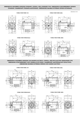
56
www.trasmissioniindustriali.com
PREMESSA - INTRODUCTION
II nuovi riduttori a vite senza fine serie CH della Chiaravalli S.p.A. nascono per venire incontro alle esigenze di parte del mercato che
richiede un prodotto di forma costruttiva e dimensionale che permetta di non modificare disegni già esistenti e garantire continuità nei
ricambi. Nell’affrontare questo nuovo prodotto Chiaravalli ha voluto comunque apportare quegli aggiornamenti tecnici che garantiscono
maggiore facilità nell’adattare i gruppi alle varie configurazioni di montaggio, con la conseguenza di poter offrire un servizio migliore
in termini di versatilità e consegna.
Dalle considerazioni sopra espresse nasce quindi un riduttore con flangia attacco motore scindibile dalla cassa la quale però incorpora
l’anello di tenuta, in questo modo la sostituzione della flangia di ingresso non comporta alcun rischio di danneggiamento dell’anello
stesso, permettendo inoltre l’eliminazione dell’O-ring. Tutti i coperchi laterali, sia pendolari che con piedi, montano O-ring al posto delle
tradizionali guarnizioni piane, in questo modo, nelle grandezze 03-04-05, la rotazione dei piedi avviene senza alcuno smontaggio degli
stessi, inoltre le versioni dotate di coperchi laterali permettono l’alloggiamento delle flange laterali da ambo le parti tramite semplici
viti di fissaggio. La vite senza fine presenta un profilo ad evolvente ZI, con questo accoppiamento vite-corona si ottiene un rendimento
maggiore ed una conseguente riduzione della temperatura. Come da tradizione Chiaravalli i riduttori, come del resto anche i motori,
sono verniciati con polveri epossidiche color alluminio RAL 9022 per proteggere le parti dall’ossidazione e per ottenere una migliore
protezione delle microsoffiature che possono essere presenti nelle pressofusioni. Le precoppie CHPC già presenti sul catalogo CHM,
possono essere montate anche su questa serie, permettendo così di ottenere rapporti di riduzione fino a 1:300, inoltre per maggiori
riduzioni è possibile la combinazione di due riduttori tramite un kit predisposto.
The new CH worm gearboxes of Chiaravalli SPA have been produced to satisfy the market that require a product in dimensions and
construction without changing the existing drawings and to guarantee non stop of their spare parts.
Chiaravalli designed this new product by improving and introducing better technical modifications to offer easier application of the groups
to the different assembling configurations so that by offering a better service in flexibility and delivery time.
Starting from these considerations , we have a gearbox with a motor mounting flange that is separable from the housing which incorporate
the oil seal; in this way we avoid any risk of damaging the oil seal in case of replacement of the input flange and the O-Ring can be
eliminated.
All the aside covers, swinging and with feet, have O-Rings instead of traditional flat gaskets. The sizes 03-04-05 allow the rotation of
the feet without disassembling them; furthermore the versions with swinging aside covers allow the lateral flanges to be fitted on both
sides with simple fixing screws.
The worm screw has a ZI involute profile: with this worm-wheel coupling we shall get a better performance with a temperature reduction.
The gearboxes and motors are painted with RAL 9022 aluminium colour epoxy powder to protect the parts from oxidation and against
micro—blowholes that can come during the pressure of die-castings.
The CHPC pre-stage gears (already present in the catalogue of CHM) can also be mounted with this range, obtaining a gear ratio up
to 1:300. For bigger reductions is possible to have two gears together using an appropriate kit.
LUBRIFICAZIONE
Tutti i gruppi vengono forniti completi di lubrificante sintetico, sono pertanto esenti da manutenzione e possono essere montati in
qualsiasi posizione, i tipi di lubrificante sono descritti nella tabella sottostante.
Lubrificante
°C ambiente
Ambiente
-25°C/+50°C
ISO
VG 320
AGIP
Telium VSF 320
SHELL
Tivela oil S 320
IP
Telium VSF
LUBRICATION
All of the groups are supplied with a synthetic lubricant maintenance free and can be mounted in any position. The types of lubricants
are described in the table here below.
Lubricant
°C ambient
Ambient
-25°C/+50°C
ISO
VG 320
AGIP
Telium VSF 320
SHELL
Tivela oil S 320
IP
Telium VSF
57
www.trasmissioniindustriali.com
QUANTITA’ OLIO LITRI - QUANTITY OF OIL IN LITRES
CH
03
04
05
06
07
08
0.035
0.055
0.090
0.38
0.52
0.73
PREDISPOSIZIONE ATTACCO MOTORE
I riduttori che vengono forniti con predisposizione attacco motore devono essere accoppiati a motori che abbiano tolleranze di albero
e flangia corrispondenti ad una qualità di classe “normale” onde evitare vibrazioni e forzature del cuscinetto in entrata, i motori forniti
da Chiaravalli garantiscono la rispondenza a queste esigenze.
Nella tabella seguente viene messa in corrispondenza la grandezza del motore B5 e B14 con le dimensioni dell’albero e della
flangia attacco motore onde agevolare la consultazione. Si ricorda che, essendo le flange attacco motore scindibili dalla cassa è sempre
possibile la combinazione di alberi e flange non corrispondenti alla tabella es.19/140, questa soluzione permette di adattarsi anche ai
motori non unificati es. brushless o corrente continua.
PAM
B5
B14
056
063
071
080
090
100
112
9/120
11/140
14/160
19/200
24/200
28/250
28/250
9/80
11/90
14/105
19/120
24/140
28/160
28/160
MOTOR MOUNTING FLANGES
Gears supplied with mounting flanges must be assembled with motors whose shaft and flange tolerances correspond to a “normal” class
of quality in order to avoid vibration and forcing of the input bearing. Motors supplied by Chiaravalli guarantee this requirement fulfilled.
For ease of consultation, the correspondence of the size of the B5 and B14 motor with the sizes of the shaft and the motor connection
flange are shown in the following table.
Remember that, as the motor connection flanges are separate from the body it is also possible to have a shaft / flange combination
that does not correspond to the table, e.g. 19/140, thereby offering adaptability for other non-unified models such as the brushless or
direct current types.
MMF
B5
B14
056
063
071
080
090
100
112
9/120
11/140
14/160
19/200
24/200
28/250
28/250
9/80
11/90
14/105
19/120
24/140
28/160
28/160
ROTAZIONE PIEDI - FEET ROTATION
I riduttori con piedi possono essere ruotati nelle posizioni N e V semplicemente svitando le viti di fissaggio, l’unico accorgimento da
adottare è quello di applicare sulle 4 viti in corrispondenza della vite senza fine, del sigillante, in quanto i fori sono passanti.
Gears with feet can be rotated into the N and V positions by simply unscrewing the fixing screws. We recommend that some sealant
is applied to the 4 screws close to the worm screw, as the holes are through holes.
58
www.trasmissioniindustriali.com
MOTORIDUTTORI E RIDUTTORI A VITE SENZA FINE
WORM GEARED MOTORS AND WORM GEAR UNITS
CH 03/04/05
CH...
CH...P
CHE...P
CHE...
CHR...
CHR...P
CHRE...P
CHRE...
www.trasmissioniindustriali.com
59
CH - CH...P 03/04/05
TIPO (1)
GRANDEZZA
VERSIONE
POS. FLANGIA (2)
i
P.A.M.
POS.MONT
TYPE (1)
SIZE
VERSION
FLANGE POS. (2)
i
M.M.F.
MOUNT. POS.
63B5
UNIVERSALE
Rapporto di riduzione
vedi pag. 62
Ratio see page 62
DESIGNAZIONE - DESIGNATION
63B14
CH
PF
1
CH..P
03
N
2
CHR
V
CHR..P
CHE
CHE..P
CHRE
CHRE..P
56B5
56B14
TIPO (1)
GRANDEZZA
VERSIONE
POS. FLANGIA (2)
i
P.A.M.
POS.MONT
TYPE (1)
SIZE
VERSION
FLANGE POS. (2)
i
M.M.F.
MOUNT. POS.
04
CH..P
PF
1
PFA
2
CHR
N
CHR..P
V
CHE
CHE..P
CHRE
CHRE..P
71B5
Rapporto di riduzione
vedi pag. 63
Ratio see page 63
CH
UNIVERSALE
71B14
63B5
63B14
TIPO (1)
GRANDEZZA
VERSIONE
POS. FLANGIA (2)
i
P.A.M.
POS.MONT
TYPE (1)
SIZE
VERSION
FLANGE POS. (2)
i
M.M.F.
MOUNT. POS.
05
CH..P
PF
1
80B5
PFA
2
80B14
CHR
N
CHR..P
V
CHE
CHE..P
CHRE
CHRE..P
Rapporto di riduzione
vedi pag. 64
Ratio see page 64
CH
71B5
71B14
63B5
63B14
ESEMPIO ORDINE - ORDER EXAMPLE
CH
CH
04P
04
FA
2
35
10
63 B14
71 B5
Nel caso venga richiesto anche il motore specificare:
If the motor is also required, please specify:
Grandezza - Size
es. 63 C4
Potenza - Power
es. Kw 0.22
Poli - Poles
es. 4
Tensione - Voltage
es. V230/400
Frequenza - Frequency es. 50 Hz
Flangia - Flange
es. B 14
N.B. Quando il riduttore è richiesto con flangia uscita F o FA deve essere ordinato versione PF o PFA.
N.B. Gear box required with output flanges F or FA must be ordered PF or PFA version.
60
1) vedi pagina 59 - see page 59
2) vedi pagina 61 - see page 61
www.trasmissioniindustriali.com
UNIVERSALE
CH 03/04/05
POSIZIONE DI MONTAGGIO - MOUNTING POSITION
B3
B6
V5
1
1
1
B7
B8
V6
1
1
1
PF1
B3
1
2
4
PF2
POSIZIONE MORSETTERIA
N.B. La posizione della morsetteria si riferisce sempre
alla pos. B3
TERMINAL BOX POSITION
N.B. The position of the terminal box always refers to
the B3 position.
3
www.trasmissioniindustriali.com
61
CH 03
PRESTAZIONI CON MOTORI A 4 POLI - 1400 GIRI ENTRATA
PERFORMANCE WITH 4-POLE MOTORS - 1400 REVS. INPUT
TIPO
i=ratio
n2 r/min
Kw=P1
Nm=T2
f.s.
Pred. attacco motore possibili
TYPE
i=ratio
n2 r/min
Kw=P1
Nm=T2
f.s.
Possible types of motor connections
CH 03
7
200
0.22
8
1.8
63/56
B5/B14
10
140
0.22
11
1.4
63/56
B5/B14
15
93
0.22
16
1.0
63/56
B5/B14
20
70
0.22
20
0.9
63/56
B5/B14
30
47
0.18
22
0.8
63/56
B5/B14
40
35
0.12
18
1.0
63/56
B5/B14
60
23
0.09
18
1.0
63/56
B5/B14
70
20
0.09
15
0.9
56
B5/B14
Peso Kg 1
Weight Kg 1
CH 03 DIMENSIONI - DIMENSIONS
81.5
105
50
46
M6
8
55
52
63
40
P
46
ø 50 h8
52
16
30
16
30
55
A
30
66
81
65
1.5
7
50
80
55
PF1
ø 80
55
7
81
50
5
68
66
50.5
80
55
52
46
30
16
55
16
97.3
N
7
66
81
46
50
52
4
52
30
30
16
16
ø 50 H8
V
50
80
62
www.trasmissioniindustriali.com
7
PRESTAZIONI CON MOTORI A 4 POLI - 1400 GIRI ENTRATA
PERFORMANCE WITH 4-POLE MOTORS - 1400 REVS. INPUT
CH 04
TIPO
i=ratio
n2 r/min
Kw=P1
Nm=T2
f.s.
Pred. attacco motore possibili
TYPE
i=ratio
n2 r/min
Kw=P1
Nm=T2
f.s.
Possible types of motor connections
7
200
0.55*
22
10
140
0.55*
30
1.0
71/63
B5/B14
14
100
0.37
29
1.0
71/63
B5/B14
20
70
0.37
38
1.0
71/63
B5/B14
28
50
0.37
40
0.9
71/63
B5/B14
35
40
0.25
41
0.9
71/63
B5/B14
46
30
0.18
37
1.0
63
B5/B14
60
23
0.18
37
0.9
63
B5/B14
70
20
0.12
33
0.9
63
B5/B14
100
14
0.12
30
0.9
63
B5/B14
CH 04
1.4
71/63
B5/B14
Peso Kg 2,1
Weight Kg 2,1
* Motori gr.71 - * Motors 71 gr.
CH 04 DIMENSIONI - DIMENSIONS
74
72
80
143,1
65
10
M6
2
81
9
98
52
PF1
44,6
24.5
9
54
65
7
81
24.5
ø 8,5
65
PFA1
54
65
71,1
44,6
60,5
52
90
64
54
9
52
98
90
87
9
81
71,1
44,6
ø 60 h8
ø 110
44,6
123,7
7
72
N
87
9
98
24.5
60 h8
72
110
65
24.5
65
35
90
64
V
54
11
44,6
P
71,1
24.5
50 h8
24.5
44,6
A
54
52,2
65
64
90
www.trasmissioniindustriali.com
ø 8,5
63
PRESTAZIONI CON MOTORI A 4 POLI - 1400 GIRI ENTRATA
PERFORMANCE WITH 4-POLE MOTORS - 1400 REVS. INPUT
CH 05
TIPO
i=ratio
n2 r/min
Kw=P1
Nm=T2
f.s.
Pred. attacco motore possibili
TYPE
i=ratio
n2 r/min
Kw=P1
Nm=T2
f.s.
Possible types of motor connections
7
10
14
18
24
28
36
45
60
70
80
100
200
140
100
78
58
50
39
31
23
20
17
14
1.1*
1.1*
0.75
0.55
0.55
0.55
0.37
0.37
0.25
0.22
0.18
0.18
40
49
57
52
67
73
61
65
60
55
54
50
CH 05
1.4
1.2
1.1
1.1
0.9
1.0
1.1
0.9
1.0
0.9
1.0
0.9
80/71
80/71
80/71
80/71
80/71
80/71
71
71
71/63
63
63
63
B5/B14
B5/B14
B5/B14
B5/B14
B5/B14
B5/B14
B5/B14
B5/B14
B5/B14
B5/B14
B5/B14
B5/B14
Peso Kg 3
Weight Kg 3
* Motori gr.80 - * Motors 80 gr.
CH 05 DIMENSIONI - DIMENSIONS
63
98,5
9
63
124
109,5
82
22
49,5
107
ø 68 h8
162,25
10
82
M6
37
94
2.5
49,5
70
PF1
22
63
10
124
82
22
63
12
109,5
85,5
70
80,25
49,5
90
9
98,5
N
ø 70 H8
82
ø 125
70
V
63
70
82
P
80,25
70
22
49,5
22
55
82
A
63
PFA1
22
70
63
64
63
124
109,5
90
9
98,5
80,25
49,5
ø 125
ø 70 H8
137,3
49.5
82
10
12
115
www.trasmissioniindustriali.com
CH 06/07/08
MOTORIDUTTORI E RIDUTTORI A VITE SENZA FINE
WORM GEARED MOTORS AND WORM GEAR UNITS
CH..
CHE..
CHR..
CHRE..
65
www.trasmissioniindustriali.com
CH 06/07/08
DESIGNAZIONE - DESIGNATION
TIPO (1)
GRANDEZZA
VERSIONE
POS. FLANGIA (2)
i
P.A.M.
POS.MONT
TYPE (1)
SIZE
VERSION
FLANGE POS. (2)
i
M.M.F.
MOUNT. POS.
CH
06
FC
1
CHR
07
F
2
CHE
08
(3)
Rapporto di riduzione
vedi pag. 68-69-70
Ratio see page
68-69-70
CHRE
100B5
100B14
90B5
90B14
80B5
80B14
71B5
71B14
ESEMPIO ORDINE - ORDER EXAMPLE
CH
06
FC
1
19
90 B5
Nel caso venga richiesto anche il motore specificare:
If the motor is also required, please specify:
Grandezza - Size
es. 90 L4
Potenza - Power
es. Kw 1.5
Poli - Poles
es. 4
Tensione - Voltage
es. V230/400
Frequenza - Frequency
es. 50 Hz
Flangia - Flange
es. B5
1) vedi pagina 65 - see page 65
2) vedi pagina 67 - see page 67
3) nessuna indicazione significa senza flangia d’uscita
lack of instructions indicates that the gear is not equipped with an output flange
66
www.trasmissioniindustriali.com
UNIVERSALE
POSIZIONE DI MONTAGGIO - MOUNTING POSITION
B3
V5
B6
1
1
1
B7
B8
V6
1
1
1
F1
B3
1
2
4
F2
POSIZIONE MORSETTERIA
N.B. La posizione della morsetteria si riferisce sempre
alla pos. B3
TERMINAL BOX POSITION
N.B. The position of the terminal box always refers to
the B3 position.
67
3
www.trasmissioniindustriali.com
PRESTAZIONI CON MOTORI A 4 POLI - 1400 GIRI ENTRATA
PERFORMANCE WITH 4-POLE MOTORS - 1400 REVS. INPUT
CH 06
TIPO
i=ratio
n2 r/min
Kw=P1
Nm=T2
f.s.
Pred. attacco motore possibili
TYPE
i=ratio
n2 r/min
Kw=P1
Nm=T2
f.s.
Possible types of motor connections
7
10
12
15
19
24
30
38
45
64
80
100
200
140
117
93
74
58
47
37
31
22
17
14
1.85
1.85
1.85
1.85
1.50
1.10
1.10
0.75
0.75
0.37
0.37
0.37
75
105
129
146
150
138
155
133
152
101
112
110
CH 06
1.5
1.3
1.1
1.0
1.0
1.1
1.0
1.1
0.9
1.2
1.0
1.0
90/80
90/80
90/80
90/80
90/80
90/80
90/80
90/80
80/71
80/71
71
71
B5/B14
B5/B14
B5/B14
B5/B14
B5/B14
B5/B14
B5/B14
B5/B14
B5/B14
B5/B14
B5/B14
B5/B14
Peso Kg 5,2
Weight Kg 5,2
CH 06 DIMENSIONI - DIMENSIONS
72.5
101
120
102
37.5
25
28,3
63
ø 75 H8
102
ø 75 H8
182.5
72.5
22.5°
8
120
8
Ø 90
M8x14
51
ø9
102
145
72.5
52
76
94
3
53
3
53
101
76
CH06FC 1
ø115 H8
ø180
CH06FC 2
ø150
45°
5
4-ø11
11
78
72.5
86
101
76
CH06F1
ø115 H8
ø180
CH06F2
ø150
68
45°
5
11
4-ø11
78
116
www.trasmissioniindustriali.com
PRESTAZIONI CON MOTORI A 4 POLI - 1400 GIRI ENTRATA
PERFORMANCE WITH 4-POLE MOTORS - 1400 REVS. INPUT
CH 07
TIPO
i=ratio
n2 r/min
Kw=P1
Nm=T2
f.s.
Pred. attacco motore possibili
TYPE
i=ratio
n2 r/min
Kw=P1
Nm=T2
f.s.
Possible types of motor connections
7
200
4
170
1.1
100/90
B5/B14
10
15
140
93
3
3
175
250
1.3
1.0
100/90
100/90
B5/B14
B5/B14
20
70
2.20
240
1.0
100/90
B5/B14
25
30
56
47
1.85
1.50
250
230
1.0
1.2
90/80
90/80
B5/B14
B5/B14
40
35
1.1
215
1.2
90/80
B5/B14
50
28
1.1
220
0.9
90/80
B5/B14
60
23
0.75
200
1.0
90/80
B5/B14
80
100
17
14
0.55
0.37
180
140
1.0
1.1
80/71
80/71
*71 solo - only B5
CH 07
B5/B14 *
B5/B14 *
Peso Kg 9,2
Weight Kg 9,2
CH 07 DIMENSIONI - DIMENSIONS
87
124
127
109.5
46.5
30
33,3
75
ø 90 H8
126
8
ø 90 H8
220.5
87
22.5°
Ø 110
M8x14
46.5
9
127
3
174
87
44
82
104
ø 10.5
126
58.5 58.5
3
124
82
CH07FC 1
ø130 H8
ø200
CH07FC 2
ø165
45°
5
12
4-ø12
90
87
85
124
82
CH07F1
ø130 H8
ø200
CH07F2
ø165
45°
5
12
4-ø12
90
111
www.trasmissioniindustriali.com
69
PRESTAZIONI CON MOTORI A 4 POLI - 1400 GIRI ENTRATA
PERFORMANCE WITH 4-POLE MOTORS - 1400 REVS. INPUT
CH 08
TIPO
i=ratio
n2 r/min
Kw=P1
Nm=T2
f.s.
Pred. attacco motore possibili
TYPE
i=ratio
n2 r/min
Kw=P1
Nm=T2
f.s.
Possible types of motor connections
7
10
15
20
23
30
40
46
56
64
80
100
200
140
93
70
61
47
35
30
25
22
17
14
4
4
4
3.00
2.20
2.20
1.85
1.5
1.1
1.1
0.75
0.55
170
240
350
340
280
340
340
340
290
290
260
220
CH 08
1.5
1.2
0.9
0.9
1.1
1.1
0.9
1.0
1.0
0.9
1.0
1.0
112/100/90
112/100/90
112/100/90
100/90
100/90
100/90
90/80
90/80
90/80
90/80
90/80
80
B5/B14
B5/B14
B5/B14
B5/B14
B5/B14
B5/B14
B5/B14
B5/B14
B5/B14
B5/B14
B5/B14
B5/B14
Peso Kg 12,2
Weight Kg 12,2
CH 08 DIMENSIONI - DIMENSIONS
100
137
140
144
45.5
3
200
100
38,3
140
57
101
125
ø 11.5
144
35
86.9
ø 110 H8
144
ø 110 H8
245.5
100
22.5°
10
11
Ø 130
M10x18
72
64.4 64.4
3
135
101
CH08FC 1
ø152 H8
ø210
CH08FC 2
ø176
45°
6
15
4-ø12.5
110.5
100
135
101
CH08F1
ø152 H8
ø210
CH08F2
ø176
70
45°
6
15
4-ø12.5
151
www.trasmissioniindustriali.com
CHR/CHRE DIMENSIONI - DIMENSIONS
CHR 06-07-08
CHR 03-04-05
A
A
B
B
f
d
d
f
I
I
H
H
CHRE 03-04-05
CHRE 06-07-08
A
A
B
C
A
B
C
A
f
d
d
f
I
I
H
H
DIMENSIONI ALBERO LENTO - OUTPUT SHAFT DIMENSIONS
D
t
b
R
TIPO TYPE
A
B
C
D(H7)
d(h6)
f
H
I
R
b
t
CHR 03
20
50
/
14
9
/
55
30
55
5
16.3
CHR 04
30
54
/
18
11
/
72
44.6
64
6
20.8
CHR 05
40
65
/
25
16
M6
82
49.5
82
8
28.3
CHR 06
40
110.5
/
25
18
M6
72.5
62.17
120
8
28.3
CHR 07
40
128
/
30
19
M6
87
75
127
8
33.3
CHR 08
50
144
/
35
25
M8
100
86.9
140
10
38.8
CHRE 03
20
50
50
14
9
/
55
30
55
5
16.3
CHRE 04
30
54
56
18
11
/
72
44.6
64
6
20.8
CHRE 05
40
65
65
25
16
M6
82
49.5
82
8
28.3
CHRE 06
40
110.5
74
25
18
M6
72.5
62.17
120
8
28.3
CHRE 07
40
128
88.5
30
19
M6
87
75
127
8
33.3
CHRE 08
50
144
101.5
35
25
M8
100
86.9
140
10
38.3
71
www.trasmissioniindustriali.com
CHPC/CH
RIDUTTORE A VITE SENZA FINE CON PRECOPPIA
WORM GEAR WITH PRE-STAGE MODULE
72
www.trasmissioniindustriali.com
RIDUTTORE A VITE SENZA FINE CON PRECOPPIA
WORM GEAR WITH PRE-STAGE MODULE
CHPC 63
CHPC 71
CHPC 80
Z
Z1
11/140
14/160
19/200
11/105
14/120
19/160
Z
Z
Z1
CHPC
ATTENZIONE: Il riduttore collegato alla precoppia
deve avere dimensioni in entrata Z1
WARNING: The gearbox connected with the pre-stage
must have input dimension Z1
DESIGNAZIONE - DESIGNATION CHPC / CH - CH..P
TIPO TYPE
GRANDEZZA SIZE
CHPC
CHPC / CHE - CH..P
i=
P.A.M. M.M.F.
63
3
63B5
71
3
71B5
80
3
80B5
ESEMPIO ORDINE - ORDER EXAMPLE
CHPC
71
CH 05
i= 108(3x36)
P.A.M. M.M.F. 71
Nel caso venga richiesto anche il motore specificare:
If the motor is also required, please specify:
Grandezza - Size
es. 71 B4
Potenza - Power
es. Kw 0.37
Poli - Poles
es. 4
Tensione - Voltage
es. V230/400
Frequenza - Frequency
es. 50 Hz
73
www.trasmissioniindustriali.com
PRESTAZIONI CON MOTORI A 4 POLI - 1400 GIRI ENTRATA
PERFORMANCE WITH 4-POLE MOTORS - 1400 REVS. INPUT
CHPC/CH
TIPO
i=ratio
n2 r/min
Kw=P1
Nm=T2
TIPO
i=ratio
n2 r/min
Kw=P1
Nm=T2
TYPE
105
138
180
210
300
13.3
10.1
7.8
6.7
4.7
0.12
0.12
0.12
0.12
0.12
42
42
46
40
36
TYPE
108
135
180
210
240
300
12.9
10.4
7.8
6.7
5.8
4.7
0.18
0.18
0.12
0.12
0.12
0.12
72
85
65
67
58
56
i=ratio
n2 r/min
Kw=P1
Nm=T2
84
108
135
16.7
12.9
10.4
0.25
0.25
0.25
80
90
90
TIPO
i=ratio
n2 r/min
Kw=P1
Nm=T2
TYPE
TIPO
i=ratio
n2 r/min
Kw=P1
Nm=T2
114
135
192
240
300
12.3
10.4
7.3
5.8
4.7
0.37
0.37
0.25
0.25
0.25
170
176
149
130
120
TYPE
120
150
180
240
300
11.7
9.3
7.8
5.8
4.7
0.55
0.37
0.37
0.37
0.25
280
215
235
210
275
i=ratio
n2 r/min
Kw=P1
Nm=T2
90
120
150
15.6
11.7
9.3
0.75
0.75
0.55
310
300
260
i=ratio
n2 r/min
Kw=P1
Nm=T2
168
192
240
300
8.3
7.3
5.8
4.7
0.55
0.37
0.37
0.37
350
280
290
275
TIPO
i=ratio
n2 r/min
Kw=P1
Nm=T2
TYPE
120
138
168
192
240
11.7
10.1
8.3
7.3
5.8
0.75
0.75
0.55
0.55
0.55
390
360
350
330
305
CHPC63
CH 04
TIPO
CHPC71
CH 05
CHPC71
CH 07
TIPO
CHPC71
CH 08
CHPC63
CH 05
CHPC71
CH 06
TIPO
CHPC80
CH 07
CHPC80
CH 08
CHPC/CH DIMENSIONI - DIMENSIONS
CHPC.. /CH 04-05
CHPC.. /CH 06-07-08
R1
I2
I2
R1
Per le altre dimensioni consultare il catalogo alle pagine 63 - 64 - 68 - 69 - 70
For other dimensions see pages 63 - 64 - 68 - 69 and 70 of the catalogue.
CHPC - CH
63
63
71
71
71
80
71
80
+
+
+
+
+
+
+
+
04
05
05
06
07
07
08
08
R1
I2
115
120
129
160
183
203
194
214
40
40
50
50
50
63
50
63
La scelta delle potenze installate è legata all’unificazione dei motori, pertanto talvolta è esuberante rispetto al riduttore, nella selezione verificare sempre la coppia massima
indicata, per ogni dubbio contattare il nostro ufficio tecnico.
The choice of power installed is tied to the unification of the motors, therefore it is sometimes in exuberance compared to the gear; always verify the maximum torque indicated
when making the selection and if in doubt please contact our technical office.
74
www.trasmissioniindustriali.com
CH - CH
RIDUTTORE A VITE SENZA FINE COMBINATO
DOUBLE WORM GEAR
75
www.trasmissioniindustriali.com
RIDUTTORE A VITE SENZA FINE COMBINATO
DOUBLE WORM GEARS
CH - CH
DESIGNAZIONE - DESIGNATION
CH(R)/CH - CH(R)/CH..P
GRANDEZZA
VERSIONE
POS. FLANGIA (1)
i
ESEC.
P.A.M.
TYPE
SIZE
VERSION
FLANGE POS. (1)
i
EXEC.
MMF
CH/CH
03/04
F
1
OAD
63B5
CH/CH..P
03/05
FA
2
OAS
63B14
CHR/CH
(2)
CHR/CH..P
Vedi pag. 78
Ratio see page 78
TIPO
OBD
56B5
OBS
56B14
VAD
VAS
VBD
VBS
GRANDEZZA
VERSIONE
POS. FLANGIA (1)
i
ESEC.
P.A.M.
TYPE
SIZE
VERSION
FLANGE POS. (1)
i
EXEC.
MMF
CH/CH
03/06
FC
1
CH/CH..P
04/07
F
2
CHR/CH
04/08
(3)
CHR/CH..P
Vedi pag. 78
Ratio see page 78
TIPO
OAD
71B5
OAS
71B14
OBD
63B5
OBS
63B14
VAD
56B5
VAS
56B14
VBD
VBS
DIMENSIONI RIDUTTORI COMBINATI CH/CH
DIMENSIONS OF CH/CH COMBINED GEARS
CH 04/CH 07-08
CH 03/CH 06
CH 03/CH 04-05
Per le esecuzioni vedi tabella con disegni pag.71, se non specificato vengono forniti OBS
For the executions see the table with drawings on page 71, if not specified OBS would be supplied.
ESEMPIO ORDINE - ORDER EXAMPLE
CH/CH
03/05P
FA
Nel caso venga richiesto anche il motore specificare:
If the motor is also required, please specify:
Grandezza - Size
es. 56 C4
Potenza - Power
es. Kw 0.09
Poli - Poles
es. 4
Tensione - Voltage
es. V230/400
Frequenza - Frequency es. 50 Hz
Flangia - Flange
es. B14
2
315
OBS
56B14
1) vedi pagine 61 e 67 - see page 61 and 67
2) nessuna indicazione significa senza flangia di uscita. In questo caso il gruppo può
essere con fissaggio a piedi CH/CH o pendolare CH/CH..P
lack of instructions indicates that the gear is not equipped with an output
flange. In this case the group can be fixed on feet CH/CH or be swinging CH/CH..P
3) nessuna indicazione significa senza flangia di uscita.
lack of instructions indicates that the gear is not equipped with an output flange.
76
www.trasmissioniindustriali.com
ESECUZIONE - EXECUTION
OAD
3
3
3
3
OAS
OBS
OBD
1
1
VAS
VAD
VBS
1
1
VBD
L’esecuzione determina la posizione di montaggio del 1° riduttore rispetto al 2° riduttore. Se non diversamente specificato in fase d’ordine il gruppo
viene fornito in esecuzione OBS. La posizione di piazzamento va riferita al 2° riduttore.
The execution determines the mounting position of the first gear in relation to the second gear. If not otherwise specified at the time
of order, the group will be supplied in the OBS execution. The placing position refers to the second gear.
www.trasmissioniindustriali.com
77
CH - CH
PRESTAZIONI CON MOTORI A 4 POLI - 1400 GIRI ENTRATA
PERFORMANCE WITH 4-POLE MOTORS - 1400 REVS. INPUT
TIPO
i=ratio
n2 r/min
Kw=P1
Nm=T2
TIPO
i=ratio
n2 r/min
TYPE
245
350
420
560
700
840
1120
1680
2100
2760
5.7
4.0
3.3
2.5
2.0
1.7
1.3
0.8
0.7
0.5
0.09
0.09*
0.09*
0.09*
0.09*
0.09*
0.09*
0.09*
0.09*
0.09*
58
58
58
58
58
58
58
58
58
50
TYPE
240
315
420
540
720
900
1120
1440
2160
2700
5.8
4.4
3.3
2.6
1.9
1.6
1.3
0.9
0.6
0.5
0.12
0.12
0.09
0.09
0.09*
0.09*
0.09*
0.09*
0.09*
0.09*
77
90
90
90
90
90
90
90
90
90
TIPO
i=ratio
n2 r/min
Kw=P1
Nm=T2
TIPO
i=ratio
n2 r/min
Kw=P1
Nm=T2
TYPE
240
315
450
570
720
900
1200
1520
2280
2700
5.8
4.4
3.1
2.5
1.9
1.6
1.2
0.9
0.6
0.5
0.22
0.22
0.18
0.12
0.12
0.12
0.12
0.09*
0.09*
0.09*
160
180
200
180
200
200
200
200
200
200
TYPE
250
300
400
525
700
920
1200
1500
2100
2800
5.6
4.7
3.5
2.7
2.0
1.5
1.2
0.93
0.67
0.5
0.37
0.37
0.25
0.25
0.18
0.18
0.12
0.12*
0.12*
0.12*
360
360
315
360
360
360
360
360
360
360
TIPO
i=ratio
n2 r/min
Kw=P1
Nm=T2
TYPE
230
300
400
525
700
920
1380
1840
2116
2760
5.6
4.7
3.5
2.7
2.0
1.5
1.2
0.93
0.67
0.5
0.55
0.55
0.55
0.37
0.37
0.25
0.18
0.18
0.12
0.12
460
490
490
490
490
490
490
490
490
490
CH
03/04
CH
03/06
CH
04/08
CH
03/05
CH
04/07
Kw=P1
Nm=T2
* Le potenze contrassegnate sono superiori a quelle ammissibili dal
riduttore, pertanto la scelta applicativa dovrà essere fatta in funzione
della coppia e non della potenza.
* The powers marked with an asterisk are higher than those that
the gear allows, therefore the applicative choice must be made in
accordance with the torque and not with the power.
DIMENSIONI RIDUTTORI COMBINATI CH/CH
DIMENSIONS OF CH/CH COMBINED GEARS
CH 03/CH 04-05
Y
Y
CH
CH
CH
CH
CH
03/04
03/05
03/06
04/07
04/08
CH 04/CH 07-08
CH 03/CH 06
Y
120.5
125.5
165
192
204.5
Per le altre dimensioni consultare il catalogo alle pagine 63 - 64 - 68 - 69 e 70.
For other dimensions see pages 63 - 64 - 68 - 69 and 70 of the catalogue.
I rapporti di riduzione indicati sono quelli maggiormente richiesti, è possibile
ottenere molteplici combinazioni utilizzando i vari rapporti dei due singoli riduttori.
The gear ratios are those most frequently requested. It is possible to obtain
multiple combinations using the various ratios of the two single gears.
78
www.trasmissioniindustriali.com
BRACCIO DI REAZIONE - TORQUE ARM
TIPO TYPE
I
A
B
ØP
ØC
Ød
H
øE
S
CH 03
100
40
157.5
50
65
7
14
8
4
CH 04
100
40
157.5
50
65
7
14
8
4
CH 05
100
55
172.5
68
94
7
14
8
4
CH 06
150
52.5
232.5
75
90
9
20
10
6
CH 07
200
62.5
300
90
110
9
25
20
6
CH 08
200
75
312.5
110
130
11
25
20
6
ød
22°30’
øC øP
ød
øC øP
I
A
I
A
B
B
øE
03-04-05
øE
H
S
06-07-08
S
H
Il punto di ancoraggio del braccio di reazione è
dotato di boccola antivibrante.
* Privo di boccola antivibrante
* Without anti vibrationbush
The anchoring point of the torque arm is equipped
with a vibration resistant bushing.
KIT ALBERO LENTO SEMPLICE - SINGLE OUTPUT SHAFT KIT
TIPO TYPE
A
Ød
B
b
t1
T
L
d2
ød1
CH 03
30
14
35
5
16
61
96
M5x13
14
CH 04
40
18
45
6
20.5
70
115
M6x16
18
CH 05
60
25
65
8
28
89
154
M8x20
25
CH 06
60
25
65
8
28
127
192
M8x20
25
CH 07
60
30
65
8
33
134
199
M10x22
30
CH 08
60
35
65
10
38
149
214
M10x25
35
t1
d h6
b
UNI 6604
DIN 6885
d h6
d2
A
B
T
L
DIN 332
KIT ALBERO LENTO DOPPIO - DOUBLE OUTPUT SHAFT KIT
TIPO TYPE
A
Ød
B
R
b
t1
L
d2
ød1
CH 03
30
14
32.5
55
5
16
120
M5x13
14
CH 04
40
18
42.7
64
6
20.5
149.4
M6x16
18
CH 05
60
25
63.2
82
8
28
208.4
M8x20
25
CH 06
60
25
63.2
120
8
28
246.4
M8x20
25
CH 07
60
30
64
127
8
33
255
M10x22
30
CH 08
60
35
64
140
10
38
268
M10x25
35
t
d h6
1
b
UNI 6604
DIN 6885
d h6
d h6
d
2
DIN 332
A
B
R
L
A
B
79
www.trasmissioniindustriali.com
COPRIMOZZO CORONA - COVER
CH 03-04-05
CH 06-07-08
C3
C3
TIPO TYPE
C3
03
37
04
42
05
55
06
70
07
85,5
08
93,5
KIT BOCCOLE DI RIDUZIONE - REDUCTION BUSHINGS KIT
SEMPLICE - SINGLE
TIPO
TYPE
ø i/ø e
ø i/ø e
DOPPIO - DOUBLE
L
L
linguette
tongues
Peso cad kit kg
Weight for kit kg
CHT BRM-S 9/11
20
4/3 x 4 x 11 RB*
0.006
CHT BRM-S 11/14
30
5/4 x 6 x 10 RB*
0.015
CHT BRM-S 14/19
40
6 x 5 x 30 *
0.045
CHT BRM-S 19/24
50
6 x 5.5 x 20 *
8 x 5.5 x 40 *
0.07
CHT BRM-S 24/28
60
8 x 9 x 40 *
0.08
CHT BRM-S 28/38
80
10 x 7 x 60 *
0.33
CHT BRM-S 38/42 110
12/10 x 10 x 48 RB*
0.22
TIPO
TYPE
CHT
CHT
CHT
CHT
ø i/ø e
ø i/ø e
BRM-D
BRM-D
BRM-D
BRM-D
11/19
14/24
19/28
24/38
L
L
linguette
Peso cad kit kg
tongues Weight for kit kg
40
50
60
80
6
8
8
10
x
x
x
x
6
7
7
8
x
x
x
x
* a disegno
* to drawing
L
L
Linguetta sec UNI 6604 - DIN 6885
Bonificate
Tongue acc. to UNI 6604 - DIN 6885
Quenched
øi
øi
øe
80
www.trasmissioniindustriali.com
øe
30
40
50
60
*
A
A
A
0.06
0.12
0.16
0.44
ESPLOSO E LISTA PARTI RICAMBIO
EXPLODED DRAWING AND SPARE PARTS LIST
CH 03/04/05
10
12
6
2
11
14
13
15
9
19
23
20
33
7
1
8
15
4
40
32
34
3
5
39
31
36
40
18
37
39
37
35
36
21
37
30
24
25
31
26
28
40
32
27
20
29
39
38
17
19
16
23
1
2
3
4
5
6
7
8
9
10
11
12
13
14
15
16
17
18
19
20
21
22
23
24
25
26
27
28
29
30
31
32
33
34
35
36
37
38
39
40
•
•
•
•
•
•
•
•
•
•
•
•
•
•
•
•
•
•
•
•
•
•
•
•
•
•
•
•
•
•
•
•
•
•
•
•
•
•
•
•
Anello di tenuta
Vite
Dado
Rondella
Vite
Flangia attacco motore
Cuscinetto
Vite p.a.m.
Vite p.a.m. + sporgenza
Anello di tenuta
Cuscinetto
Chiavette
Vite sporgente
Vite bisporgente
Chiavetta
Tappo olio
Guarnizione
Cassa
Anello di tenuta
Coperchio con piedi
Coperchio pendolare
Flangia uscita
Vite
Cuscinetto
Seeger
Distanziale
Seeger
Cappellotto
Anello di tenuta
Corona
Cuscinetto
O-ring
Braccio di reazione
Vite
Albero lento semplice
Chiavetta
Chiavetta
Albero lento doppio
Distanziale
Seeger
1
2
3
4
5
6
7
8
9
10
11
12
13
14
15
16
17
18
19
20
21
22
23
24
25
26
27
28
29
30
31
32
33
34
35
36
37
38
39
40
•
•
•
•
•
•
•
•
•
•
•
•
•
•
•
•
•
•
•
•
•
•
•
•
•
•
•
•
•
•
•
•
•
•
•
•
•
•
•
•
Oil seal
Screw
21
Nut
Washer
Screw
22
Flangia attacco motore
Bearing
Hole input worm
Hole input and shaft output worm
Oil seal
Bearing
Key
Shaft input worm
Double extended input shaft worm
Key
Oil plug
Gasket
Casing
Oil seal
Foot cover
Side cover
Output flange
Screw
Bearing
Seeger
Spacer
Seeger
Cap
Oil seal
Worm wheel
Bearing
O-ring
Braccio di reazione
Screw
Single output shaft
Key
Key
Double output shaft
Spacer
Seeger
23
81
www.trasmissioniindustriali.com
CH 06/07/08
1
2
3
4
5
6
8
9
10
11
12
13
14
15
16
17
18
19
20
21
22
23
24
25
26
27
28
29
30
31
32
33
34
35
36
37
Anello di tenuta
Vite torx
Dado
Rondella
Vite testa esagonale
Flangia attacco motore
Rasamento
Cuscinetto
Vite p.a.m.
Vite p.a.m. + sporgenza
Anello di tenuta
Coperchio entrata
Cuscinetto
Chiavetta
Vite sporgente
Vite bisporgente
Chiavetta
Tappo olio
Cassa
Anello di tenuta
Flangia uscita
Vite testa esagonale incassata
Cuscinetto
Seeger
Anello di tenuta
Cappellotto
Cuscinetto
Corona
O-ring
Coperchio uscita
Seeger
Distanziale
Chiavetta
Chiavetta
Albero lento doppio
Albero lento semplice
ESPLOSO E LISTA PARTI RICAMBIO
EXPLODED DRAWING AND SPARE PARTS LIST
1
2
3
4
5
6
8
9
10
11
12
13
14
15
16
17
18
19
20
21
22
23
24
25
26
27
28
29
30
31
32
33
34
35
36
37
Oil seal
Torx screw
Nut
Washer
Hexagonal-head screw
Motor connection flange
Adjust spacer
Bearing
Hole input worm
Hole input and shaft output worm
Oil seal
Input cover
Bearing
Key
Shaft input worm
Double extended input shaft worm
Key
Oil plug
Casing
Oil seal
Output flange
Embedded hexagonal-head screw
Bearing
Seeger
Oil seal
Cap
Bearing
Worm wheel
O-ring
Output cover
Seeger
Spacer
Key
Key
Double output shaft
Single output shaft
82
www.trasmissioniindustriali.com
CH
CARICHI RADIALI SULL’ALBERO LENTO
RADIAL LOADS ON THE OUTPUT SHAFT
I carichi indicati valgono in qualunque direzione di applicazione.
I carichi assiali massimi ammissibili sono pari a 1/5 del valore del carico radiale indicato in tabella quando sono applicati in
combinazione con il carico radiale stesso, in caso diverso vi preghiamo di contattare il ns. ufficio tecnico.
Se vengono utilizzati alberi lenti doppi, la somma dei carichi radiali applicabili alle mezzerie delle due estremità d’albero, non
devono superare il valore indicato nella tabella sottoindicata.
I carichi radiali riferiti ai giri di uscita (n2)=10 sono i massimi sopportabili dal riduttore.
The loads indicated are valid for all application directions.
The maximum allowable axial loads are equal to 1/5 of the radial load value shown in the table when applied with the same radial
load; if this is not the case, please contact our technical office. If double output shafts are used, the sum of radial loads applicable
to the centre lines of the two ends of the shaft must not exceed the value shown in the table below.
The radial loads related to the output speed (n2)=10 are the maximum loads supported by the gear.
a
b
x
FRX
FR
FA
Costante del riduttore
Costante del riduttore
Distanza del carico dalla battuta dell’albero in mm.
Carico radiale nella posizione x (in N)
Carico radiale (N)
Carico assiale (N)
FR
FA =
a
b
x
FRX
FR
FA
Gear constant
Gear constant
Load distance from shaft shoulder in mm.
Radial load in position x (in N)
Radial load (N)
Axial load (N)
==
1
FR
5
FRX = FR
X
a
b+x
FRX
GRANDEZZE - SIZES
Giri di uscita
Output speed
400
250
150
100
60
40
25
10
03
04
05
06
07
08
490
580
690
790
940
1070
1260
1700
720
860
1010
1160
1380
1570
1850
2500
1000
1190
1400
1600
1910
2160
2550
3450
1450
1720
2020
2330
2770
3130
3700
5000
1800
2140
2510
2880
3440
3890
4590
6200
2020
2420
2840
3260
3880
4380
5180
7000
VALORI DELLE COSTANTI - CONSTANTS’ VALUES
a
b
60
45
71
51
99
69
130
102
136
108
146
118
83
www.trasmissioniindustriali.com
CH
CARICHI RADIALI SULLA MEZZERIA DELL’ALBERO VELOCE
RADIAL LOADS ON THE CENTRE LINE OF THE INPUT SHAFT
FR
==
GRANDEZZE - SIZES
FR max
03
04
05
06
07
08
100
150
220
700
975
1150
Note: i valori delle tabelle sono espressi in N
Notes: value of tables are in N
84
www.trasmissioniindustriali.com
CH
ISTRUZIONI USO E MANUTENZIONE RIDUTTORI A VITE SENZA
FINE E PRECOPPIE
USE AND MAINTENANCE INSTRUCTIONS
INSTALLAZIONE
· I dati riportati sulla targhetta identificativa devono corrispondere
al riduttore ordinato.
· Tutti i riduttori vengono forniti completi di olio sintetico
permanente in quantità idonea a qualsiasi posizione di
montaggio.
· Il fissaggio del riduttore deve avvenire su superfici piane e
sufficientemente rigide in modo da evitare qualsiasi vibrazione.
· Il riduttore e l’asse della macchina da movimentare devono
essere in perfetto allineamento.
· In caso si prevedano urti, sovraccarichi o blocchi della macchina
il cliente dovrà provvedere all’istallazione di limitatori, giunti,
salvamotori etc.
· Gli accoppiamenti con pignoni, giunti, pulegge ed altri organi
devono essere fatti previa pulizia delle parti ed evitando urti
nel montaggio poiché questo potrebbe danneggiare i cuscinetti
ed altre parti interne.
· Nel caso il motore sia di fornitura del cliente questi dovrà
accertarsi che le tolleranze di flangia ed albero corrispondono
ad una classe “normale”, i nostri motori rispondono a questa
esigenza.
· Verificare che le viti di fissaggio del riduttore e dei relativi
accessori siano correttamente serrate.
· Adottare gli opportuni accorgimenti per proteggere i gruppi
da eventuali agenti atmosferici aggressivi.
· Dove previsto proteggere le parti rotanti da possibili contatti
con gli operatori.
· Nel caso i riduttori vengano verniciati proteggere gli anelli di
tenuta ed i piani lavorati.
· Tutti i riduttori sono verniciati colore grigio RAL 9022.
FUNZIONAMENTO E RODAGGIO
· Per ottenere le migliori prestazioni è necessario provvedere
ad un adeguato rodaggio dei riduttori incrementando la potenza
gradualmente nelle prime ore di funzionamento, in questa fase
un aumento delle temperature è da considerarsi nella norma
· In caso di funzionamento difettoso, rumorosità, perdite olio
etc. arrestare immediatamente il riduttore e, dove possibile,
rimuovere la causa, in alternativa inviare il pezzo alla nostra
sede per i controlli.
MANUTENZIONE
· I riduttori a vite senza fine dalla grandezza 03 alla grandezza
08 e le precoppie sono lubrificate con olio sintetico permanente,
pertanto non richiedono alcuna manutenzione.
CONSERVAZIONE A MAGAZZINO
· Nel caso di lunga conservazione a magazzino, superiore a tre
mesi, si consiglia di proteggere alberi e piani lavoratori con
antiossidanti e di ingrassare gli anelli di tenuta.
MOVIMENTAZIONE
· Nella movimentazione dei gruppi dovrà essere posta molta
attenzione a non danneggiare gli anelli di tenuta ed i piani
lavorati.
SMAL TIMENTO IMBALLI
· Gli imballi in cui vengono consegnati i nostri riduttori andranno
avviati, dove possibile, al riciclo degli stessi tramite le ditte
preposte.
INSTALLATION
· The data shown on the identification name plate must correspond
to the gear ordered.
· All the gears are supplied complete with permanent synthetic
oil in a quantity that is sufficient for any assembly position.
· The gear must be fixed on a flat surface that is sufficiently
rigid in order to avoid any vibration.
· The gear and the axis of the machine to be driven must be
perfectly aligned.
· In the event that knocks, overloading or blockage of the
machine are foreseen, the client must install a limiting device,
joints, overload cut-out etc.
· Coupling with pinions, joints, pulleys and other parts must be
done after the parts have been cleaned and knocks should be
avoided whilst assembling as they could damage the bearings
and other internal parts.
· In the event that the motor is supplied by the client, he must
check that the flange and shaft tolerances correspond to a
“normal” class; our motors satisfy this requirement.
· Check that the fixing screws for the gear and the related
accessories are correctly tightened.
· Take suitable measures to protect the groups from any
aggressive atmospheric agents.
· Where foreseen, protect rotating parts from any possible
contact with the operators.
· If the gears are painted, protect the oil seals and the machined
surfaces.
· All of the gears are painted RAL 9022 grey.
OPERATION AND RUNNING-IN
· To obtain the best performance the gears must first be runin by gradually increasing the power in the first few hours of
operation, in this phase an increase in temperature is considered
normal.
· In the event of defective operation, noise, oil leakage, etc.
stop the gear immediately and, when possible, remove the
cause. Alternatively, send the piece to our factory to be
controlled.
MAINTENANCE
· The worm gears from size 03 to size 08 and the pre-stage
modules are lubricated with permanent synthetic oil and
therefore do not require any maintenance.
WAREHOUSE STORAGE
· If the warehouse storage will be for a long time, more
than 3 months, the shafts and machined surfaces should
be protected using antioxidants and the oil seals should be
greased.
HANDLING
· Care must be taken not to damage the oil seals and the
machined surfaces when handling the groups.
DISPOSAL OF PACKAGING
· The packaging in which our gears are delivered should be
sent to specialised companies for recycling if possible.
85
www.trasmissioniindustriali.com
Scarica