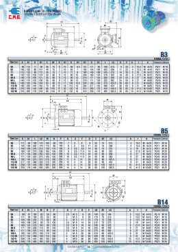
Motori elettrici
Electric motors
ALLUMINIO 56-160
ALUMINIUM 56-160
3
Motori elettrici – Electric motors
L’Azienda
The company
Elpromtech è un'azienda leader nel settore dei motori
elettrici asincroni.
Fondata a Parma, dal 1963 progetta, sviluppa e realizza
prodotti di elevata qualità che combinano prestazioni
tecniche notevoli, materiali selezionati e design innovativo
in grado di soddisfare i clienti più esigenti a livello
internazionale.
Elpromtech is a leader company in the field of asynchronues
electric motor market.
Since 1963, year of its foundation in Parma, Elpromtech has
designed, developed and produced high quality motors for a
wide variety of industrial applications. Our modern product
design and careful material selection satisfy all customer needs
worldwide.
I motori Elpromtech sono stati concepiti per fare fronte
alle più svariate esigenze dell’industria e della
progettazione di macchine ed impianti.
Si possono avere oltre alle caratteristiche costruttive ed
elettriche standard, motori con caratteristiche speciali
realizzati su specifiche sia meccaniche che elettriche e
meccanico fornito dal cliente.
The Elpromtech motors range is thought to face the wide range
of needs of industry and in the projects of machines and plants.
It is possible to have standard mechanical and electrical
characteristics, or special motors with features realized under
specific request and mechanical and electrical “design” given
by the customer.
L’obiettivo dell’azienda è
quello
di soddisfare
completamente le richieste ed aspettative dei clienti
fornendo prodotti di elevate qualità. Con questa politica
Elpromtech ha ottenuto nell’anno 2000 la certificazione
ISO 9001 per la progettazione, produzione e vendita di
motori asincroni monofase e trifase a bassa tensione.
The Company mission is to completely satisfy the requirements
and the expectations of our customers providing cutting-edge
high quality products.
With this policy Elpromtech got in year 2000 the ISO 9001
certification for design, manufacture and sale of single-phase
and three-phase low voltage asynchronous motors.
Nell’anno 2002 Elpromtech ha ottenuto
la rinomata certificazione che attesta
che I suoi prodotti rispettano i severi
parametri
stabiliti
dale
Autorità
Canadesi ed Americane riguardanti
sicurezza e qualità.
In the year 2002, Elpromtech obtained
the renowned certification attesting
that its own products respect the
severe parameters stated by the
American and Canadian authorities
regarding security and quality.
Con questa certificazione Elpromtech è approdata sul
mercato degli USA diventando fornitore preferenziale di
uno dei più grandi e meglio organizzati Gruppi Americani.
With such a certification Elpromtech arrived in the USA market
became a selected supplier of one of the largest and better
organized American Group.
A partire dall’anno 2003 Elpromtech è presente in
Germania ed Austria con una sua agenzia specializzata.
In questo modo, Elpromtech isi espande in uno dei
mercati più competitive ed esigenti dell’Europa, trovando
clienti che necessitano di prodotti speciali e di alta qualità.
Since year 2003 Elpromtech is actively present in Germany and
Austria through a specialized agency.
Elpromtech is in this way expanding in one of the most
competitive and exigent market in Europe especially finding
where the customer asks for special and high quality products.
Nell’anno 2009 Elpromtech ottiene la
certificazione ATEX per la produzione
di motori idonei all’utilizzo in atmosfere
esplosive.
In the year 2009 Elpromtech ottiene la
certificazione ATEX per la produzione di motori
idonei all’utilizzo in atmosfere esplosive.
Questo consente di andare ad arricchire ulteriormente la
sua gamma di prodotti e garantire un ulteriore
ampliamento della sua presenza sul mercato europeo in
altri importanti stati quali, Inghilterra, Spagna, Olanda,
Belgio e paesi Scandinavi.
This certification allows to further widen the products range
and to expand the presence in the Europea market in other
important countries like, England, Spain, Holland, Belgium and
Scandinavian countries.
Nell’anno 2010 Elpromtech inizia la produzione dei motori
ad alta efficienza IE2 in conformità alle disposizioni della
Direttiva Europea 2005/32/CE.
In the year 2010 Elpromtech start the production of high
efficiency motors IE2 in compliance with the European Directive
2005/32/EC.
Dal 2011 Elpromtech fa parte del gruppo Orange One
From year 2011 Elpromtech is part of Orange One group
2014 certificato IECEx per motori antideflagranti
2014 IECEx certificate of flameproof motors
Motori elettrici – Electric motors
INDICE / CONTENTS
1. GAMMA DI PRODOTTI / RANGE OF PRODUCTS............................................................................ 6
2. MOTORI STANDARD / STANDARD MOTORS................................................................................... 7
2.1
Tolleranze e norme di riferimento/ Tolerances and standards of reference......................................... 7
2.2 Principali caratteristiche / Main features ................................................................................................... 8
2.3 Opzioni principali / Main options ................................................................................................................ 9
2.4 Identificazione del motore / Motor identification ..................................................................................... 10
2.5 Collegamenti elettrici / Electrical connections ........................................................................................ 11
2.6
Caratteristiche meccaniche / Mechanical characteristics .................................................................... 12
2.7
Sollecitazioni radiali ed assiali sull’albero / Radial and axial forces on the shaft end ....................... 13
2.8
Parti di ricambio, revisioni e riparazioni / Spare parts, overhauls and repairs ................................... 14
2.9 Motori resinati / Encapsulated motors..................................................................................................... 14
2.10 Dati elettrici / Electrical data .................................................................................................................... 15
2.11 Dimensioni di ingombro / Overall dimensions ....................................................................................... 19
3. MOTO-INVERTER ................................................................................................................................. 20
3.1 Caratteristiche generali / General features............................................................................................. 20
3.2 Dimensioni di ingombro / Overall dimensions ........................................................................................ 22
4. MOTORI POWER PACK / POWER PACK MOTORS ...................................................................... 23
5. MOTORI IMMERSI IN OLIO / UNDER OIL MOTORS ....................................................................... 24
5.1 Dati elettrici / Electrical data .................................................................................................................... 24
5.2 Dimensioni di ingombro / Overall dimensions ........................................................................................ 25
5.3 Motori con marcatura CSA / CSA approved motors .............................................................................. 25
ELPPROM_GEN_ it_ en_2015/0
Motori elettrici – Electric motors
1. Gamma di prodotti / Range of products
CSA Motori standard
CSA Standard motors
Motori asincroni trifasi e monofasi con rotore a
gabbia di scoiattolo costruiti in conformità a EN
50347 e IEC 60072-1 realizzati in carcassa e scudi
di alluminio sabbiati pressofusi con corpo alettato
per un ottimale raffreddamento.
Three-phase and single-phase asynchronous
motors manufactured in compliance with EN 50347
and IEC 60072-1 realized with body and shields in
press died sand blasted aluminium, with a finned
body for a proper cooling surface.
I motori saranno marcati
con classe di
rendimento IE2 quando realizzati secondo gli
standard Europei.
these motors will bear the
marking with
efficiency class IE2 when manufactured in
compliance with the European standards.
I motori saranno marcati
quando realizzati
secondo gli standard Nord Americani.
These motors will bear the
manufactured in compliance
America standards.
Motori incapsulati
Encapsulated motors
Particolare tipologia di motore, le cui parti elettriche
interne sono completamente impermeabilizzate
grazie a una speciale resina epossidica.
Applicabile a tutti i modelli.
Particular motor type, all the inner electrical parts
are completely sealed thanks to a special epoxy
resin. Applicable on all models.
Motoinverter
Motoinverter
motori con azionamento a velocità variabile
integrato. L'azionamento a velocità variabile viene
alloggiato nella scatola morsettiera studiata
appositamente per ridurre al minimo gli ingombri.
Risulta di facile installazione persino in luoghi con
spazio estremamente ridotto.
motor with a frequency inverter integrated into the
terminal box.
This box remains of extremely reduced dimensions
comparing to the traditional motor terminal boxes
and it allows an easy installation even in very
reduced space.
Power pack
Power pack
I motori elettrici sono largamente utilizzati nelle
applicazioni idrauliche, nella maggior parte dei casi
con particolari giunti e flange di adattamento tra
motore e centralina. La serie Powerpack presenta
flange e alberi speciali che permettono un
accoppiamento diretto tra motore e pompa.
La flangia quadrata speciale si adatta alle più
comuni centraline sul mercato.
The electric motors are largely used in the
hydraulic applications, with special couplings and
adaptors between the motor and the pump.
Our Powerpack series has special flanges and
shafts that allow a direct coupling between motor
and pump.
The special square flange is suitable for the main
pump brands on the market.
Motori immersi in olio
Under oil motors
Motore studiato per funzionare immerso in olio,
direttamente accoppiato ad una pompa ad
ingranaggi.
Caratteristiche principali sono la grande affidabilità,
la compattezza e l’utilizzo di materiali particolari
resistenti all’olio. Il rotore è disegnato in modo tale
da evitare la formazione di turbolenze nel
serbatoio.
Motor for direct coupling to the gear pump oil
submersed into the tank.
The under oil motor is very reliable and compact,
designed with special oil resistant materials.
The rotor is designed with smooth surfaces to
avoid oil turbulence inside the tank.
I motori saranno marcati
quando realizzati
secondo gli standard Nord Americani.
These motors will bear the
manufactured in compliance
America standards.
marking when
with the North
marking when
with the North
Motori elettrici – Electric motors
2. Motori standard / Standard motors
2.1
Tolleranze e norme di riferimento/ Tolerances and standards of reference
Simbolo
Symbol
A
AB
AC
B
C - CA
Descrizione
Distanza tra fori fissaggio piedi (vista frontale)
Distanza tra i piedi (vista frontale)
Diametro del motore (senza scatola morsettiera)
Distanza tra fori fissaggio piedi (vista laterale)
Distanza tra battuta albero e primo foro dei piedi di
fissaggio
Distance between centre-lines of fixing holes (end view)
Overall dimensions across the feet (end view)
Diameter of the motor (without terminal box)
Distance between centre-lines of fixing holes (side view)
Distance from the shaft end shoulder to the centre-line of
nearest mounting holes in the feet
D - DA
Diametro estremità albero
Diameter of the shaft extension
E - EA
Lunghezza estremità albero a partire dalla battuta
Length of the shaft extension from the shoulder
F - FA
Larghezza sede chiavetta su estremità albero
Distanza tra la parte superiore della chiavetta e la
superficie opposta dell'estremità albero
Width of the keyway of the shaft extension
Distance from the top of the key to the opposite surface
of the shaft extension
Distance between the centre-line of the shaft to the
bottom of the feet
Distance from the top of the terminal box and to the
bottom of the feet
Diameter of the holes or width of the slots in the feet of
the motor
GA - GC
H
Distanza tra centro albero e base dei piedi motore
Tolleranza
Tolerance
Description
Diametro battuta flangia
Diameter of the spigot
P
Diametro esterno flangia
R
Distanza tra battuta albero e battuta flangia
Diametro dei fori di fissaggio flangia di supporto o
diametro nominale del filetto
Distanza tra battuta albero e battuta flangia, con
cuscinetto bloccato
Massa del motore
Tensione nominale
Efficienza
Outside diameter of the flange
Distance from the shaft shoulder to the mounting surface
of the flange
Diameter of the fixing holes in the mounting flange or
nominal diameter of thread
Distance from the shaft shoulder to the mounting surface
of the flange with locked bearing
Mass of the motor
Nominal voltage
Efficiency
Fattore di potenza
Power factor
Perdite totali (rpm) (a pieno carico e temperature
ambiente nominale)
Slip (rpm) (full load and nominal ambient temperature)
Corrente di avviamento a rotore bloccato
Coppia di avviamento a rotore bloccato
Coppia massima
Coppia Minima
Momento di Inerzia
Livello sonore (pressione sonora)
Locked rotor current
Locked rotor torque
Breakdown torque
Minimum torque
Moment of Inerti
Sound intesiti level (sound pressure)
S
VN
η
cos ϕ
PN
IA
MA
Mmax
Mmin
J
LpfA
Ø < 55 mm
Ø > 60 mm
- 0,3 mm
+ 0,5 mm
+ 0,2 mm
N
L
j6
k6
m6
H ≤ 250
H ≥ 280
M
K
± 3 mm
Ø 11 – 28
Ø 32 – 48
Ø ≥ 55
h9
Distanza tra parte superiore della scatola morsettiera e
base dei piedi motore
Diametro dei fori o larghezza delle scanalature nei
piedi del motore
Lunghezza totale motore con una sola estensione
albero
Distanza tra i centri dei fori fissaggio flangia
HD
± 1 mm
+2%
+2%
± 1 mm
+2%
+3%
Overall length of the motor with a single shaft extension
+1%
Pitch circle diameter of the fixing holes
Titolo
Title
Macchine elettriche rotanti
Rotating electrical machines
Parte 1: Caratteristiche nominali e di funzionamento
Part 1: Rating and performance
Parte 2: Metodi per la determinazione, mediante prove, delle
Part 2-1:Standard methods for determining losses and
perdite e del rendimento delle macchine elettriche rotanti
efficiency from tests (excluding machines for traction
(escluse le macchine per veicoli di trazione)
vehicles)
Parte 5: Gradi di protezione degli involucri delle macchine
Part 5: Degrees of protection provided by the integral design
rotanti (progetto integrale) (Codice IP) - Classificazione
of rotating electrical machines (IP code). Classification
Parte 6: Metodi di raffreddamento (Codice IC)
Part 6: Methods of cooling (IC Code)
Parte 7: Classificazione delle forme costruttive e dei tipi di
Part 7: Classification of types of construction, mounting
installazione nonché posizione delle morsettiere (Codice IM)
arrangements and terminal box position (IM Code)
Parte 9: Limiti di rumore
Part 9: Noise limits
Parte 12: Caratteristiche di avviamento dei motori asincroni
Part 12: Starting performance of single-speed three-phase
trifase a gabbia, ad una sola velocità
cage induction motors
Parte 14: Vibrazioni meccaniche di macchine con altezza
Part 14: Mechanical vibration of certain machines with shaft
d'asse uguale o superiore a 56 mm - Misura, valutazione e
heights 56 mm and higher - Measurement, evaluation and
limiti della intensità di vibrazione
limits of vibration severity
Motori asincroni trifase di uso generale con dimensioni e
General purpose three-phase induction motors having
potenze normalizzate
standard dimensions and outputs. Frame numbers 56 to 315
Grandezze da 56 a 315 e numeri di flangia da 65 a 740
and flange numbers 65 to 740
Gradi di protezione degli involucri (Codice IP)
Degrees of protection provided by enclosures (IP Code)
CSA Standard C22.2 No.100-95 : Motors and Generators
UL Standard 1004 : Electric motors
CSA Standard C22.2 No.14-95 : Industrial Control Equipment
UL Standard 508-01 : Industrial Control Equipment
- 0,5 mm
- 1 mm
± 0,8 mm
Ø < 230 j6
Ø ≥ 250 h6
± 1 mm
± 3 mm
+3%
± 0,5 mm
– 5 a + 10 %
±5%
-15% of (1-η)
-1/6 of (1-cos ϕ)
min 0.02, max 0.07
±20% se PN ≥ 1 kW
±30% se PN < 1 kW
+20%
-15% +25%
-10% con Mmax /MN ≥ 1.6
-15%
±10%
3 dBA
EN 60034-1
IEC 60034-1
EN 60034-2
IEC 60034-2
EN 60034-5
IEC 60034-5
EN 60034 -6
IEC 60034 -6
EN 60034-7
IEC 60034-7
EN 60034-9
IEC 60034-9
EN 60034-12
IEC 60034-12
EN 60034-14
IEC 60034-14
EN 50347
IEC 60072-1
EN 60259
-
IEC 60529
-
Motori elettrici – Electric motors
2.2 Principali caratteristiche / Main features
Motori realizzati secondo gli standard Nord Americani e riportare la
Marcatura cCSAus. Master Contract 256222
Motors cCSAus manufactured in compliance with the North
America standards. Master Contract 256222
CSA standard C22.2 n.100-95: motors and general
CSA standard C22.2 n.14-95 : Industrial control equipment
UL standard 1004 : Electric motors
UL standard 508-01: Industrial control equipment
The motors range is thought to face the wide range of needs of
I motori sono stati concepiti per fare fronte alle più svariate esigenze
industry and in the projects of machines and plants.
dell’industria e della progettazione di macchine ed impianti.
Si possono avere oltre alle caratteristiche costruttive ed elettriche
It is possible to have standard mechanical and electrical
standard, motori speciali realizzati su specifica richiesta e “design”
characteristics, or special motors with special features realized under
elettrico e meccanico fornito dal cliente.
Una seria procedura nella progettazione e costruzione, oltre ad un specific request and mechanical and electrical “design” given by the
rigoroso collaudo finale, assicurano un’alta qualità del motore in customer.
A serious procedure in projecting and construction, a serious final
conformità agli standard Europei (marchio CE) e nord Americani
check out assures a high quality of the motors in conformity to
(Marchio cCSAus).
European standards (CE marking) and North America standards
Un certificato di collaudo può essere richiesto dal cliente facendo (cCSAus marking).
A test certificate could be requested from the customer referring to
riferimento al numero di matricola impresso sulla targa.
Tutti i motori sono realizzati in carcassa e scudi di alluminio sabbiati the serial number printed on the motor nameplate.
All the motors are realized with body and shields in press died sand
pressofusi con corpo alettato per l’opportuno raffreddamento.
Tutti i motori sono asincroni con rotore a gabbia di scoiattolo, statore blasted aluminium, with a finned body for a proper cooling surface.
All the motors are asynchronous with squirrel cage rotor, wound
avvolto, chiusi ed esternamente ventilati secondo EN 60034-6 (IC
stator, closed and externally ventilated in comply with EN 60034-6 (IC
411).
411).
The supply voltages allowed can exceed the nominal value of ±5%.
La tensione di alimentazione ammessa può variare rispetto ai
All the electrical and mechanical features and the testing methods
valori nominali del ±5%.
Tutte le caratteristiche elettriche e meccaniche ed i metodi di prova comply with the standard EN 60034-1.
sono conformi alla norma EN 60034-1.
The power ratings and the dimensions of the motors comply with
Le potenze e dimensioni dei motori sono conformi a EN 50347 ed
IEC 60072-1, le forme costruttive B3, B5, B14 sono conformi a EN EN 50347 and IEC 60072-1, the mounting arrangements B3, B5, B14
comply with EN 60034-7.
60034-7.
All the geometrical dimensions are unified following the tables UNEL
Tutte le dimensioni geometriche sono unificate secondo le tabelle
13113-71; 13117-71; 13118- 7; IEC 60072-1.
UNEL 13113-71; 13117-71; 13118- 7; IEC 60072-1.
Il grado di protezione IP dei motori è conforme a EN 60034-5 e EN
The IP degrees of protection of the motors comply with EN 60034-5
60259.
and EN 60259.
Classe di isolamento. Tutti i motori hanno una classe di isolamento
Insulation class. All the motors have an insulation class F in
F in conformità con EN 60034-1. Classe di isolamento H su richiesta.
compliance with EN 60034-1. Insulation class H on request.
Cuscinetti. Sono cuscinetti radiali a sfere ad una corona di alta
The bearings are high-quality single raw deep grooves ball bearings,
preloaded by a wave spring.
qualità, precaricati con anello ondulato.
Servizio. Normalmente I motori hanno servizio S1, altrimenti si
Duty. The motors are normally built for S1 duty; otherwise
possono realizzare motori a servizi intermittenti dopo opportuna intermittent duties can be done on request after performing the heating
verifica termica.
tests.
Motori monofase
Single-phase motors
Condensatore posizionato sul motore o all’interno di apposita scatola
Capacitor placed on the motor or in a special terminal box.
morsettiera.
Avvolgimenti
Windings
Realizzati con filo di rame doppio smalto (classe di isolamento H).
Made using enamelled copper wires are insulated by two layers
(insulation class H). They are painted with another layer of varnish and
Successiva verniciatura per impregnazione ed essiccazione in forno.
E’ inoltre possibile tropicalizzare gli avvolgimenti usando un after this placed in an oven so to dry it.
impregnante particolare avente ottime caratteristiche igroscopiche così
It is also possible to tropicalize the windings using special additional
da permettere l’utilizzo in luoghi con elevata umidità >60% (Vedi varnish with high hygroscopic characteristics so to be used in places
with an humidity >60% (see options)
opzioni).
Rotori
Rotors
A gabbia di scoiattolo con barre e corone in alluminio pressofuso (o
Die-cast aluminium squirrel cage or aluminium alloy (Al-Si Silumin).
leghe di alluminio come Al-Si Silumin).
The shafts of the motors and the keys-shaft comply IEC 60072-1.
Gli alberi motore e le relative chiavette sono conformi a IEC 60072- Special shaft are made on request (see options).
Alberi speciali possono essere realizzati su richiesta (vedi opzioni).
Corpo motore (conforme a EN 50347)
Frame (in compliance with EN 50347)
In alluminio presso fuso ad elevate resistenza meccanica, ottima
Die-cast aluminium with high mechanical strength, with a good
conducibilità termica e peso contenuto.
thermal conductivity and light weight.
I piedi possono essere montati nella posizione preferita (in basso
The feet can be mounted on the motor frame in 3 different positions,
oppure ai lati).
in the bottom or on right and left side.
Scatola morsettiera
Terminal box
La scatola della morsettiera è posta normalmente al di sopra The terminal box is normally positioned on the top of the body
della carcassa ma può essere posta lateralmente su richiesta. but vìcan be mounted on the sides on request. Degree of
Grado di protezione fino ad IP65.
protection till IP65.
Flange e scudi (conformi a EN 50347)
Flanges and shields (in compliance with EN 503471)
Alluminio pressofuso, dimensioni secondo la norma EN 50347, o con
Die-cast aluminium, with dimensions as per standard IEC 60072-1, or
forme speciali su richiesta.
with special shapes on request:
Ventilazione (conforme a EN 60034-6)
Ventilation (in compliance with EN 60034-6)
Motori autoventilati IC 411. Ventola in materiale plastico, su richiesta
Self-ventilated motors IC 411. Plastic fan and on request in
in alluminio.
aluminium.
Copriventola
Fan cover
Lamiera stampata e zincata con fori adatti per impedire l’ingresso pressed steel sheet, provided with a grate to avoid the entry of
di corpi estranei e la ventola in plastica adatta per un improper objects, and the plastic fan is good for a bi-directional
raffreddamento con rotazione bidirezionale.
cooling.
Rumorosità (conforme a EN 60034-9)
Noise (in compliance with EN 60034-9)
Motori elettrici – Electric motors
2.3 Opzioni principali / Main options
Albero bloccato assialmente
Motori aventi cuscinetto anteriore bloccato tramite un anello metallico
elastico. Questa soluzione è necessaria nel caso sollecitazioni assiali
alternate (ad es. ingranaggio conico con carico o movimento alternato,
frequenti avviamenti sotto carico o grande inerzia) che possono creare
movimenti assiali dell’albero e compressione dei cuscinetti.
Esecuzione per basse temperature (-30°C) (IEC 56 ... IEC 160)
I motori in esecuzione standard possono funzionare a temperatura
ambiente fino a -15°C. Per temperatura ambiente fin o a -30°C il
motore deve essere realizzato con: cuscinetti speciali, ventola di lega
leggera, pressacavi e tappi metallici. In questi casi, se ci sono pericoli
di formazione di condensa, è consigliabile richiedere anche
l'esecuzione "Impregnazione supplementare.
Fori scarico condensa
Motori realizzati con opportuni fori per lo scarico della condensa che
si forma in particolari condizioni climatiche. Nella designazione motore
indicare la reale forma costruttiva di impiego, ossia la posizione del
motore durante il suo impiego, che determina la posizione dei fori. I
motori vengono consegnati con i fori chiusi da tappi.
Scaldiglie anticondensa (IEC80 ... IEC160)
Per motori installati in luoghi freddi e umidi con notevoli escursioni
termiche, la formazione di condensa può essere pericolosa per la
resistenza di isolamento degli avvolgimenti. Su richiesta, si possono
applicare opportune scaldiglie anticondensa, direttamente sulle testate
di avvolgimento. I terminali sono collegati ad una morsettiera all'interno
della scatola di collegamento del motore.
Le scaldiglie sono disponibili in versione a 110V e 220V.
Impregnazione supplementare avvolgimenti
Motori realizzati con una protezione degli avvolgimenti superiore al
normale contro agenti elettrici (picchi di tensione da rapide
commutazioni o da inverter con elevati gradienti di tensione), ambienti
aggressivi (ambienti umidi e corrosivi, muffe) o meccanici (vibrazioni
meccaniche o elettromagnetiche indotte: es. da inverter).
Tensione e frequenze speciali
I motori trifase standard vengono realizzati per le seguenti tensioni e
frequenze nominali:
230/400V ,50 Hz - fino 4 kW, 400/690V 50Hz oltre 4kW.
I motori funzionano alla tensione nominale con una tolleranza del
±5%.
Su richiesta è possibile realizzare motori e tensioni e frequenze
speciali.
Alberi speciali
Su richiesta, è possibile fornire i motori con alberi speciali su disegno
del cliente.
E’ inoltre possibile fornire il motore con materiale speciale diverso da
quello standard ( C40 ), per esempio in acciaio inossidabile o altri
materiali.
Flange speciali
Grazie alla modularità del motore è possibile avere, su richiesta,
flange speciali.
Tettuccio parapioggia
Per applicazioni all’esterno, montaggio verticale, albero rivolto verso
il basso ( V5, V1, V18 ) si suggerisce di utilizzare copriventola muniti i
tettuccio parapioggia. E’ disponibile per tutte le grandezze motore.
Sonde termiche a termistori (PTC)
Motori realizzati con tre termistori in serie, inseriti negli avvolgimenti,
da collegare a opportuna apparecchiatura di sgancio. Terminali
collegati a una morsettiera volante in scatola morsettiera. Si ha una
repentina variazione di resistenza quando la temperatura degli
avvolgimenti raggiunge la temperatura di intervento. Su richiesta sono
fornibili termistori con diverse temperature di intervento.
Sonde termiche bimetalliche
Motori realizzati con due o tre sonde in serie con contatto
normalmente chiuso e inserite negli avvolgimenti.
Corrente nominale 1,6 A, tensione nominale 250 V c.a.
Si ha l'apertura del contatto quando la temperatura degli avvolgimenti
raggiunge la temperatura di intervento.
Su richiesta sono fornibili bimetalliche con diverse temperature di
intervento.
Il contatto NC (normalmente chiuso) del termoprotettore deve essere
collegato in modo da intervenire direttamente sul circuito di
alimentazione della bobina del contattore del motore, provocandone
l'apertura.
Axially locked shaft
Motors with a locked bearing on the font shield using an elastic metal
ring. This solution is necessary in case of alternative axial stress (ie.
Bevel gear pinion with alternative load or motion, frequent start-up
under load or with high inertia) so to create axial movement of the
shaft and bumps on the bearings.
Special design for low temperatures (-30 °C) (IEC 56 ... IEC 160)
The motors in standard design can work in enviroment temperature
down to –15°C. For temperatures down to –30°C it is advisable to use
special bearings, alluminium alloy fan, metallic cable gland and plugs.
In these cases if there is a danger of condensate, it is advisable to use
the special execution “Additional winding impregnation” and eventually
the execution “Condensate drain holes” and “Anti-condensation
heaters”.
Condensate drain holes
Motors designed with drain holes to take off the motor the water
raised from particular environment conditions. In this execution the
motors are supplied with holes closed by plugs. Always advise to
Technical Department the real mounting position of the motor before
positioning the holes on the motor frame.
Anti-condensation Heaters (IEC80 ... IEC160)
For motors installed in cold and wet places, with significant
temperature ranges, moisture condensation can be dangerous for the
resistance of the winding insulation. Upon request, we can apply
appropriate heaters directly on the heads of winding.
The terminals are connected to a terminal board inside the
connection box of the motor.
The heaters are available at 110V and 220 V.
Additional winding impregnation
Motors designed with an additional protection of the windings against
electrical stresses (high voltage peaks from inverter drive application),
aggressive environment (humidity and mildew) or mechanical agents
(high mechanical or electrical vibration). It consists of a second
impregnation cycle after stator winding assembling.
Special voltages and frequencies
The standard three phase motors are produced at the following
nominal voltages and frequencies:
230/400V 50 Hz fino a 4kW, 400/690V 50Hz oltre 4kW.
The motors can run at a different voltage with a tolerance of +/- 5%
On customer request, we can produce motors with special voltage
and frequency.
Special shafts
On customer request, it is possible to supply motors with special
shaft as customer drawing.
It is possible to supply motors with shaft material different from the
standard ( C40 ), using Stainless Steel or others, with standard
dimensions or special as customer drawing.
Special flanges
Due to the modular flange assembling is possible to have, on request
special flanges.
Rain fan cover
For outdoor applications, vertical mounting, DE shaft down ( V5, V1,
V18 ) it is suggested to assemble a special cowl with a rain cover. It is
available for all the frame sizes.
Thermistors (PTC)
Motors designed with three thermistors in series, inserted into the
windings, for connection to a suitable contact breaker device. Cables
connected to a flying terminal block. A sharp variation in resistance
occurs when the temperature of the windings reaches the setted
temperature. Different setting temperatures are available.
Bi-metal thermal switch
Motor designed with two or three bi-metal switches in series with NC
(Normally Closed) contact and inserted
into the windings.
Nominal current 1,6 A, nominal Voltage 250 V AC.
The NC contact opens when the temperature reaches the setted value.
Different setting temperatures are
available.
The NC contact must be connected to the main motor circuit breaker.
Motori elettrici – Electric motors
Motore monofase ad avvolgimento bilanciato - BIFASE
Balanced windings single phase motors
Motore monofase in esecuzione ad avvolgimento bilanciato per
Single phase motors with balanced windings suitable for single
agevolare il collegamento di inversione del senso di marcia.
connection for reversing. Power usually equal to that of the single
Potenze normalmente uguali al motore in esecuzione monofase; phase motor design. Ask to Technical Department for details.
contattare l'Ufficio Tecnico per maggiori dettagli.
Condensatore ausiliario con disgiuntore elettronico
Per ottenere elevate coppie di spunto (Ms/Mn 1,25-1,6), è disponibile
un condensatore ausiliario che dopo l'avviamento del motore si
disinserisce automaticamente per mezzo di un disgiuntore elettronico
incorporato nel motore. Il disgiuntore elettronico prevede l'utilizzo di
TRIAC ed è quindi di elevata affidabilità anche nel caso di carichi
inerziali elevati.
Auxiliary capacitor start with electronic switch
Execution to obtain high starting torques (Ms/Mn 1,25-1,6) using an
auxiliary starting capacitor that is switched off after the starting by
means of an electronic switch included into the motor.
The electronic device uses a TRIAC switch, highly reliable also in
cases of high inertia loads.
Verniciatura (protezione contro la corrosione)
Painting (against corrosion)
I motori Elpromtech vengono prodotti con componenti in alluminio
The Elpromtech motors have diecasted aluminium components and
pressofuso e sabbiati. Se non espressamente indicato non è prevista sandblasted. If it is not requested the motors are supplied unpainted.
nessuna verniciatura.
On specific request and for batches of not less than 30 pcs. , it is
In caso di necessità e per lotti non inferiori a 30 pezzi, è possibile possible to have painted motors with epoxy paint, with the customer
verniciare il motore con vernice epossidica del colore scelto dal cliente. requested colour.
Su richiesta è possibile utilizzare altri tipi di vernice con
Other paints with anti salt characteristics are available on request.
caratteristiche anti-sale.
Motore servoventilato
Forced ventilation
Il ventilatore ausiliario è posto all’interno di un copriventola speciale The auxiliary fan is placet in sode a special fan cowl longer than the
con lunghezza superiore allo standard. Può avere alimentazione standard one. It can be single-phase or three-phase and have a
trifase o monofase e scatola morsettiera indipendente.
separate terminal box.
Motore senza ventola (per ventilatore esterno al motore)
Motore senza ventola, con scudo lato opposto comando
completamente chiuso con caratteristiche elettriche e potenza
immutate rispetto a quelle del motore normale. Esecuzione per
ventilatori o per applicazioni in cui il raffreddamento è assicurato
dall'ambiente esterno e dal flusso d'aria del ventilatore esterno.
Esecuzione idonea anche quando il servizio è saltuario e di durata
così breve da non richiedere raffreddamento.
Motor without ventilation (external air stream)
Motors without fan with non-drive-end shield completely closed having
the same electrical characteristics of the standard motors. Designed
for fan application where the air stream guarantee the proper motor
cooling. Design suitable also where the duty cycle is intermittent
periodic and of short duration that do not require ventilation.
Motore senza ventola (convezione naturale)
Motore senza ventola, con raffreddamento esterno per convezione
naturale e scudo lato opposto comando completamente chiuso.
Avvolgimento elettrico e caratteristiche elettriche sono diversi dal
motore normale e la potenza subisce un declassamento:
orientativamente moltiplicare per 0,2 il valore della potenza per il
motore normale a 2 poli, per 0,3 per il 4 poli, per 0,5 per il 6 e 8 poli
(interpellarci per la verifica di ogni specifico caso).
Motor without ventilation (natural convection)
Motors without ventilation with natural convection cooling and nondrive-end shield completely closed.
Electrical characteristics different from standard ventilated motors. The
power must be derated:multply the power value by 0,2 for 2 poles, by
0,3 the 4 poli, by 0,5 6 and 8 poles (ask to check every specific case).
Motore certificato a norme CSA e UL (IEC56 ... IEC160)
Motore certificato sia a norme canadesi (CSA C22.2 No. 100-95) che
statunitensi (UL 1004) anche nell'esecuzione con 9 o 12 morsetti.
Esecuzione normalmente utilizzata per il mercato Nordamericano.
Il marchio cCSAus ha la stessa valenza dei marchi UL e CSA. Infatti
le norme ed i test di riferimento sono gli stessi previsti per entrambi i
marchi ed il marchio è riconosciuto dall' OSHA (Occupational Safety
and Health Administration) per tutto il Nord America ed il Canada
Motors certified CSA and UL (IEC56 ... IEC160)
Certified motor for both Canadian standards (CSA C22.2 No. 100-95)
and American (UL 1004) also with 9 or 12 pins.
The cCSAus mark has the same validity of UL or CSA. The standard
and the tests are the same for both marks and is recognized by the
OSHA (Occupational Safety and Health Administration) for all the
North America and Canada.
2.4 Identificazione del motore / Motor identification
U
Tipo / Type
Grandezza motore / Motor size
Lunghezza statore / Stator lenght
N° poli / Poles n°
Forma costruttiva / Mounting arrangements
Tensione / Voltage
Frequenza / Frequency
Protezione IP / IP protection
Verniciatura / Painting
Protettori termici / Thermal protectors
O
0
6
3
A
4
F
2
3
0
5
A
Z
P
Motori elettrici – Electric motors
2.5 Collegamenti elettrici / Electrical connections
Motore con piedi riportati, è possibile montarli in 3 differenti
posizioni in modo da avere la scatola morsettiera sia in alto che sul
lato destro e sinistro del motore (vedi figura 1)
Allo stesso modo la scatola morsettiera può essere montata sul
motore in modo da avere l’uscita cavi dove è necessario. Pertanto
gli ingressi cavi possono essere i 4 diverse posizioni (vedi figura 2).
Motor with removable feet, it is possible to fix them in 3 different
positions so to have the possibility to have the terminal box on the
top or on the right and left sides of the motor (see picture 1)
At the same time the terminal box can be mounted on the motor
so to have the cable entries where it is necessary. So the cable
entries can be in the four different positions (see picture 2).
Posizioni / Positions
Pressacavi
Cable glands
1st
2nd
M20
M16
M20
M16
M20
M16
M20
M20
M20
M20
M20
M20
M20
M20
M32
M32
M32
M32
Grandezza motore
Motor size
56
63
71
80
90
100
112
132
160
2
1
Collegamenti elettrici / wiring connections
TRIFASE 1 VELOCITA’ 2-4-6-8 POLI (6 fili)
SINGLE SPEED 3-ph 2-4-6-8 POLES (6 wires)
W2 U2 V2
W2 U2 V2
U1
U1
L1
V1 W1
L2 L3
Tensione inferiore
Lower volatge
TRIFASE 1 VELOCITA’ 2-4-6-8 POLI (9 fili)
SINGLE SPEED 3-ph 2-4-6-8 POLES (9 wires)
T4
T7
V1 W1
L2 L3
L1
Tensione superiore
Higher volatge
TRIFASE DOPPIA VELOCITA’ 1 AVVOLGIMENTO
DOUBLE SPEED 3-ph SINGLE WINDING
T5 T6
T8 T9
T4 T5 T6
T7 T8 T9
T1 T2 T3
T1 T2 T3
L1
L2 L3
Tensione inferiore
Lower volatge
Tensione superiore
Higher volatge
TRIFASE DOPPIA VELOCITA’ AVVOLGIMENTI SEPARATI
DOUBLE SPEED 3-ph SEPARATE WINDINGS
W2
U2 V2
W2 U2 V2
W2
U2 V2
W2 U2 V2
U1
V1 W1
U1 V1
U1
V1 W1
U1 V1
L1
L2 L3
L3
W1
L1 L2
Bassa velocità
Low speed
L1
Alta velocità
High speed
L2 L3
W2
U2 V2
W2
U1
V1 W1
U1 V1
N
L1
L3
W1
L1 L2
Bassa velocità
Low speed
MONOFASE 4 FILI
SINGLE PHASE 4 WIRES
L1
L2 L3
L1
Alta velocità
High speed
MONOFASE 3 FILI
SINGLE PHASE 3 WIRES
U2 V2
W1
N
Rotazione oraria
Rotazione antioraria
Clockwise rotation
Counter clockwise rotation
(Vista lato albero – shaft side view)
W2
U2 V2
W2
U1
V1 W1
U1 V1
L1
N
U2 V2
N
W1
L1
Rotazione oraria
Rotazione antioraria
Clockwise rotation
Counter clockwise rotation
(Vista lato albero – shaft side view)
Motori elettrici – Electric motors
2.6
Caratteristiche meccaniche / Mechanical characteristics
Forme costruttive / Mounting arrangements
IM 1001 (IM B3)
IM 1051 (IM B6)
Montaggio con piedi / Foot mounted
IM 1061 (IM B7)
IM 1071 (IM B8)
M 1011 (IM V5)
IM 1031 (IM V6)
IM 3001 (IM B5)
IM 3011 (IM V1)
Flangiati / Flange mounted
IM 3031 (IM V3)
IM 3601 (IM B14)
IM 3611 (IM V18)
IM 3631 (IM V19)
IM 2001 (IM B35)
IM 2011 (IM V15)
Flangiati con piedi / Foot-flange mounted
IM 2031 (IM V36)
IM 2101 (IM B34)
IM 2111 (IM V58)
IM 2131 (IM V69)
Principali componenti
Componente
Component
Materiale
Carcassa / Frame
Scudi / End- shields
Flangia B5 / Flange B5
Flangia B14 / Flange B14
Scatola morsettiera / Terminal box
Albero / Shaft
Rotore / Rotor
Statore / Stator
Avvolgimento / Winding
V-Ring
Cuscinetti / Bearings
Ventola / Fan
Alluminio – Aluminium [Piedi smontabili / removable feet (71-160)]
Alluminio - Aluminium
Alluminio - Aluminium
Alluminio - Aluminium
Alluminio - Aluminium
Acciao C40 - Steel C40
Lamiera magnetica alluminio pressofuso / Magnetic lamination die-cast aluminium
Lamiera magnetica - Magnetic lamination
Fili di rame smaltato (doppio strato) - enamelled copper wires (two layers)
Gomma NBR – NBR rubber
Cuscinetti a sfere - Deep groove ball bearings (Vedi sotto / see below)
Plastica – Plastic (Su richiesta/on request: Aluminium)
Cuscinetti e tenute / Bearings and seals
Grandezza motore
Motor size
56
63
71
80
90
100
112
132
160
Cuscinetti / Bearings
Anteriore/ Drive end
Posteriore / Non-drive end
6201-ZZ
6201-ZZ
6202-ZZ
6202-ZZ
6202-ZZ
6202-ZZ
6204-ZZ
6204-ZZ
6205-ZZ
6205-ZZ
6206-ZZ
6206-ZZ
6306-ZZ
6306-ZZ
6308-ZZ
6308-ZZ
6309-ZZ
6309-ZZ
Tenute/ Seals
Anteriore/ Drive end
Posteriore / Non-drive end
v-Ring Ø12
v-Ring Ø12
v-Ring Ø14
v-Ring Ø14
v-Ring Ø14
v-Ring Ø14
v-Ring Ø20
v-Ring Ø20
v-Ring Ø25
v-Ring Ø25
v-Ring Ø30
v-Ring Ø30
v-Ring Ø30
v-Ring Ø30
v-Ring Ø40
v-Ring Ø40
v-Ring Ø45
v-Ring Ø30
I motori Ex Elpromtech sino alla grandezza 160 sono equipaggiati
con cuscinetti permanentemente lubrificati del tipo 2Z, lubrificati con
un grasso speciale G-15 ed hanno una temperatura di servizio
massima di 150°C.
The motors up to frame size 112 are normally fitted with
permanently greased bearings of type 2Z, lubricated with a special
grease G-15 and have a service max temperature of 150°C.
La durata di vita dei cuscinetti per motori in alluminio è
approssimativamente (in funzione delle applicazioni e carichi):
• motori 2 poli, 10 000 - 20 000 ore di servizio
• motori 4, 6, 8 poli, 20 000 - 40 000 ore di servizio
The bearing life time for aluminium motors is approximately
(depending on application and load conditions):
• 2 and 2/4 pole motors, 10 000 - 20 000 duty hours
• 4 to 8 pole motors, 20 000 - 40 000 duty hours
Sia sullo scudo anteriore che posteriore sono montate delle tenute
V-ring per avere un grado di protezione IP66.
Both on drive end and non-drive end are mounted V-ring seals to
have the IP66 protection.
Motori elettrici – Electric motors
2.7 Sollecitazioni radiali ed assiali sull’albero / Radial and axial forces on the shaft end
2.7.1 Carichi radiali ammissibili / Permissible radial load
Here we show the permissible radial load (FR) that can be applied to three
different positions (X0, L/2 and L where L is the length of the shaft axis) on
the shaft-end, supposing motors running at 50Hz and bearings life time at
least 20,000 hours for 2 poles motors and 40,000 hours for 4-6-8 poles. For
service on 60Hz reduce values by 10%. Take the higher speed as reference
for double pole motors.
Qui sotto indichiamo I carichi radiali ammissibili (FR)in tre diverse posizioni
dell’albero (X0, L/2 ed L dove L è la lunghezza nominale della parte
terminale dell’albero), supponendo il motore funzionante a 50Hz ed un
durata di vita dei cuscinetti si almeno 20,000 ore per motori 2 poli e 40,000
ore per motori 4-6-8 poli. Per funzionamento a 60Hz tali valori andranno
ridotti del 10%. Per i motori doppia polarità prendere come riferimento la
velocità più alta.
FR in un punto dell’albero con generica posizione X / FR in a point of the shaft with generic position X: F R=FX0 –(FX0-FL)X/L
Carichi radiali ammissibili / Permissible radial load
Motore
Motor
56
63
71
80
90S
90L
100
112
132
160
Albero
Shaft
L (mm)
20
23
30
40
50
50
60
60
80
110
3000 rpm
X0
350
390
490
650
720
720
1020
1410
1520
2750
L/2
1500 rpm
L
325
365
450
590
645
650
920
1280
1370
2455
300
340
410
530
570
580
820
1150
1220
2160
X0
350
390
490
650
720
720
1020
1410
1520
2750
L/2
325
365
450
590
645
650
920
1280
1370
2455
1000 rpm
L
X0
300
340
410
530
570
580
820
1150
1220
2160
450
560
750
820
830
1160
1610
1540
2750
L/2
750 rpm
L
420
515
680
735
750
1045
1455
1465
2600
X0
390
470
610
650
670
930
1300
1390
2450
610
820
910
920
1290
1780
1910
3430
L/2
565
745
815
830
1165
1610
1720
3055
L
FR
520
670
720
740
1040
1440
1530
2680
X
L
L/2
X0
Applicazioni con puleggia e cinghia il carico max radiale FR è dato da:
For Belt drive applications the maximum radial load FR is given by:
F R = massimo carico radiale [N] = (P + F) dove:
• P = peso della puleggia [N]
• F = tensione della cinghia [N] = (2 · K · M)/D dove:
• K = fattore di tensione della cinghia
(K= 3 per cinghia piatta senza tendicinghia, K = 2,2 per V–belt, K = 2
per cinghia piatta con tendicinghia)
• D = diametro puleggia [m]
• M = coppia [Nm] = 9550 · P/n dove:
• P = potenza all’albero [kW]
• n = velocità in [1/min]
F R = maximum radial load [N] = (P + F) where:
• P = pulley weight [N]
• F = belt tension [N] = (2 · K · M)/D where:
• K = belt tension factor
(K = 3 for normal flat belt without idler pulley; K = 2,2 for V–belt; K = 2
for normal flat belt with idler pulley)
• D = pulley diameter [m]
• M = torque [Nm] = 9550 · P/n where:
• P = output [kW]
• n = speed in [1/min]
2.7.2 Carichi assiali ammissibili / Permissible axial load
La tabella sotto sono riporta i carichi assiali massimi (FA) ammissibili nel caso
in cui il massimo carico radiale (FR) sia applicato in L.
In the table below we show the additional axial load (FA) allowable if the
maximum radial load (FR) is applied on L.
FR
Minore è il carico radiale applicato, maggiore è il carico
assiale applicabile.
Il calcolo del carico assiale sono stati effettuati in tre
differenti forme costruttive:
orizzontale (B3), verticale con albero rivolto verso il basso
(V5) e verticale con l’albero rivolto verso l’alto (V6),
supponendo il caso di spinta S e tiraggio T.
The lower is radial load, the bigger is allowable axial load.
Axial load calculations have been carried out in three
different foot mounting operating conditions:
horizontal (B3), vertical shaft-down (V5) and vertical shaftup (V6), supposing the case of thrust T or pull P force.
FA
L
Carico radiale max applicato in L / Maximum radial load in L
T
220
240
300
400
430
440
620
860
920
1680
4 poli
P
T
100 220
110 240
140 300
190 400
200 430
200 440
290 610
400 850
430 920
800 1670
6 poli
8 poli
2 poli
P
T
P
T
P
T
100
230
110 280 120 290 120 250
130 350 160 380 170 320
180 460 210 510 240 430
210 500 230 550 260 460
200 510 240 560 260 480
290 710 330 780 370 680
400 980 460 1080 500 950
430 1050 500 1170 550 1080
800 1920 920 2120 1010 1940
4 poli
6 poli
Spinta/Thrust
2 poli
Tiro/Pull
Tiro/Pull
Motore
Motor
56
63
71
80
90S
90L
100
112
132
160
IM 1031 (IM V6)
Tiro/Pull
M 1011 (IM V5)
Spinta/Thrust
IM 1001 (IM B3)
8 poli
P
T
P
T
P
T
90 230 90
100 250 100 290 110 290
120 320 110 370 140 400
160 440 140 500 170 550
170 470 170 540 190 590
160 490 150 560 190 610
230 690 210 790 250 860
320 960 290 1090 350 1190
270 1130 220 1260 290 1380
540 1970 500 2220 620 2420
2 poli
P
T
220
110 230
150 280
200 370
220 400
210 400
290 560
390 780
340 760
710 1420
P
100
120
160
220
230
240
350
480
590
1060
4 poli
T
220
130
280
360
390
390
530
740
710
1370
P
100
120
150
220
250
250
370
510
640
1100
6 poli
T
270
330
420
460
460
630
870
840
1620
P
130
180
250
270
290
410
570
710
1220
8 poli
T
280
360
470
510
510
700
970
960
1730
P
130
190
280
300
310
450
610
760
1370
Motori elettrici – Electric motors
2.8
Parti di ricambio, revisioni e riparazioni / Spare parts, overhauls and repairs
Revisioni e riparazioni devono essere effettuate solo da personale
Overhauls and repairs must be only realised by qualified people in
qualificato. Le revisioni e riparazioni devono essere effettuate in
accordance with the national standards and laws (last edition).
accordo con le leggi e normative nazionali (ultima revisione).
In case these rules are not respected, ELPROMTECH liability is
Nel caso in cui tali regole non siano rispettate la responsabilità di released.
ELPROMTECH viene a cessare.
Tutte le parti del motore devono essere sostituite con parti di
All motors components must be replaced by original spare parts. In
ricambio originali. In questi casi siete pregati di contattare
these cases please contact ELPROMTECH directly and give the
direttamente ELPROMTECH e indicare il numero di matricola del
serial number of the motor so to ask the authorization to repair the
motore in modo da richiedere anche l’autorizzazione alla
motor too.
riparazione stessa.
In case you have to contact Elpromtech technical and quality
Nel qual caso siete pregati di contattare l’ufficio tecnico e l’ufficio
department.
qualità di Elpromtech.
1
2
3
4
5
6
7
Scudo anteriore – Flange / Drive end shield – Flanges
Carcassa completa di avvolgimento / Frame complete with winding
Scudo posteriore / Rear shield
Scatola morsetti / Terminal box
Coperchio scatola morsetti / Terminal box cover
Piedi (smontabili dal 71 al 160) / Feet (removable from 71 to 160)
Albero complete di rotore / Shaft complete of rotor
5
8
9
10
11
12
13
14
Cuscinetti / Bearings
Chiavetta albero / Shaft key
Molla di compressione / Wave spring
Ventola / Fan
Copriventola / Fan cover
Pressacavo / Cable gland
Morsettiera / Terminal board
14
13
4
9
1
2
6
8
7
8
10
3
11
12
2.9 Motori resinati / Encapsulated motors
I prodotti Elpromtech si ampliano con la serie di motori incapsulati
resistenti all’acqua.
Uno speciale processo, che utilizza una resina epossidica bicomponente, rende le parti interne completamente resistenti all’acqua.
Il motore è resistente agli ambienti più ostili, in termini di presenza di
acqua ed umidità.
Questa soluzione migliora inoltre la trasmissione del calore
dell’avvolgimento e l’isolamento dello stesso.
E’ applicabile a tutto il range di motori riportati in questo capitolo.
Elpromtech products widens with the encapsulated waterproof motor
range.
A special process, using an epoxy bi-compound, makes the internal
electrical parts completely waterproof.
The motor is resistant to the most hostile environments in terms of
presence of water and humidity.
This is a solution improves also the heating transmission and electrical
insulation of the winding.
The solution is applicable to all the catalogue range.
Specifiche della resina epossidica:
Max temperature ammissibile155°C , Rigidità dielett rica 21 KV/mm
Epoxy casting bi-compound specifications:
Max admissible temperature155°C , Dielectric streng th 21 KV/mm
Campi di applicazione - esempi:
• Industria alimentare
• Impianti lavaggio automobili
• Industria del pesce
• Tutte le applicazioni con grande presenza di acqua
Field of application - examples:
• Food industry
• Car wash plants
• Fishing and fish converting industries
All application with high degree of rain and high water influence
Motori elettrici – Electric motors
2.10 Dati elettrici / Electrical data
MOTORI TRIFASE 1 VELOCITA’
THREE PHASE MOTORS 1 SPEED
Tipo
Type
56A2
56B2
63A2
63B2
71A2
71B2
80A2
80B2
90S2
90L2
IE2
100L2
112M2
132S2
132M2
160S2
IE3
160M2
160L2
[kW]
rpm
η
cosφ
φ
0,09
0,12
0,18
0,25
0,37
0,55
0,75
1,1
1,5
2,2
3
4
5,5
7,5
11
15
18,5
2750
2680
2825
2750
2850
2840
2800
2800
2840
2840
2860
2860
2900
2900
2945
2945
2940
64%
50%
56%
60%
71%
70%
77,4%
79,6%
81,3%
83,2%
84,6%
85,8%
87,0%
88,1%
89,4%
90,3%
90,9%
0,67
0,76
0,76
0,83
0,78
0,78
0,73
0,81
0,86
0,85
0,86
0,86
0,88
0,87
0,90
0,90
0,92
MOTORI TRIFASE 1 VELOCITA’
THREE PHASE MOTORS 1 SPEED
Tipo
Type
56A4
56B4
63A4
63B4
71A4
71B4
80A4
80B4
90S4
90L4
100K4
IE2
100L4
112M4
132S4
132M4
160M4
IE3
160L4
[kW]
rpm
η
cosφ
φ
0,06
0,09
0,12
0,18
0,25
0,37
0,55
0,75
1,1
1,5
2,2
3
4
5,5
7,5
11
15
1400
1370
1350
1350
1400
1410
1430
1400
1420
1420
1430
1430
1430
1450
1450
1460
1460
35%
50%
56%
56%
55%
66%
68%
79,6%
81,4%
82,8%
84,3%
85,5%
86,6%
87,7%
88,7%
89,9%
90,6%
0,6
0,6
0,75
0,67
0,81
0,68
0,71
0,75
0,78
0,76
0,78
0,79
0,78
0,79
0,79
0,85
0,86
MOTORI TRIFASE 1 VELOCITA’
THREE PHASE MOTORS 1 SPEED
3000
400V 50Hz
IN
[A]
0,32
0,5
0,62
0,74
1
1,45
1,9
2,4
3
4,5
5,9
7,5
10,4
14
19,4
26,3
31,5
MN
[Nm]
0,31
0,43
0,61
0,87
1,24
1,85
2,6
3,8
5
7,4
10
13,4
18,1
24,6
36
49
60
MA/MN
Mmax/MN
3,83
2,9
3,9
3,3
4,5
4,9
5
5,5
6
6,5
7
6,9
7
6,8
7
7
7
3
2
2,6
1,8
2,4
3,3
2
2,2
2,2
2,4
2,5
2,4
2,4
2,4
2,4
2,4
2,4
3,2
2,8
3,6
2,5
2,7
3,4
2,5
2,7
2,8
3,1
3,2
2,9
3
2,8
3,1
3,1
3,2
IA/IN
MA/MN
Mmax/MN
2,5
2,8
2,5
2,5
3,8
3,9
4,3
4,5
4,5
5
5
5
5,5
6
6,1
6,9
7
2,3
2,3
1,8
2,1
2,4
2,5
2,7
2
2
2,1
2,1
2,2
2,4
2,5
2,5
2,7
2,9
2,5
2,5
2
2,2
2,8
2,9
3,2
2,4
2,4
2,6
2,6
3,6
2,8
2,9
2,9
3,2
3,3
Jrotor
[kgm2]
0,00010
0,00012
0,00017
0,00022
0,00035
0,00045
0,00087
0,00100
0,00180
0,00230
0,00450
0,00680
0,01500
0,01800
0,04400
0,05100
0,06500
[kg]
2,2
2,5
4
4
6
6,5
9
11
13
15
20
28
46
49
100
105
115
1500
400V 50Hz
IN
[A]
0,41
0,43
0,44
0,66
0,84
1,2
1,75
1,8
2,5
3,4
4,8
6,4
8,5
11,4
15,4
20,5
27,5
IA/IN
MN
[Nm]
0,41
0,63
0,88
1,3
1,7
2,52
3,75
5,2
7,4
10
14,7
20,1
26,7
36,3
49,3
72
98
Jrotor
[kgm2]
0,00015
0,00015
0,00021
0,00029
0,00073
0,00080
0,00092
0,00128
0,00203
0,00265
0,00450
0,00599
0,01112
0,02311
0,02953
0,06167
0,08276
[kg]
2,2
2,4
4
4
5,5
6
7
11
12
14
19
23
30
39
55
85
110
1000
400V 50Hz
Tipo
Type
[kW]
rpm
η
cosφ
φ
IN
[A]
MN
[Nm]
IA/IN
MA/MN
Mmax/MN
Jrotor
[kgm2]
[kg]
71A6
71B6
80A6
80B6
90S6
90L6
100L6
112M6
IE2
132S6
132M6
132L6
160M6
IE3
160L6
0,18
0,25
0,37
0,55
0,75
1,1
1,5
2,2
3
4
5,5
7,5
11
900
910
940
930
920
920
920
930
940
940
940
960
960
62%
63%
58%
65%
75,9%
78,1%
79,8%
81,8%
83,3%
84,6%
86%
87,2%
88,7%
0,7
0,6
0,66
0,65
0,71
0,71
0,73
0,73
0,73
0,75
0,75
0,72
0,78
0,61
1
1,4
2
2
2,9
3,7
5,3
7,1
9
12,3
17,1
23
1,95
2,7
3,76
5,72
7,8
11,4
15,5
22,5
30,5
40,5
55,8
74
109
3
2,9
4
2,7
3,5
3,5
4
5
5,4
5,3
4,7
5,5
6,9
2
3,1
2,7
2,3
1,7
1,7
1,7
1,9
2
2,1
1,9
2,2
2,9
2,3
3,3
3,2
2,4
2
2
2,1
2,5
2,6
2,7
2,6
2,5
3,2
0,00060
0,00080
0,00220
0,00282
0,00340
0,00460
0,00900
0,01300
0,02500
0,03200
0,03800
0,03630
0,07200
7
7,5
9
11
13
16
22
38
43
50
55
85
105
IA/IN
MA/MN
Mmax/MN
2,8
2,9
3
3
3,4
3,7
3,7
3,4
4
4,1
4
4,2
2,7
2,8
1,6
2,4
2,3
2,2
1,3
1,6
1,6
2
2
1,9
3
3,2
2
2,7
2,5
2,6
2,2
2,5
2
2,3
2,4
2,4
MOTORI TRIFASE 1 VELOCITA’
THREE PHASE MOTORS 1 SPEED
Tipo
Type
80A8
80B8
90S8
90L8
100K8
100L8
112M8
132S8
132L8
160S8
160M8
160L8
[kW]
rpm
η
cosφ
φ
0,18
0,25
0,37
0,55
0,75
1,1
1,5
2,2
3
4
5,5
7,5
690
700
680
690
700
700
710
710
700
710
715
720
49%
55%
60%
65%
65%
63%
77%
75%
78%
82%
85%
86%
0,6
0,55
0,67
0,65
0,65
0,69
0,72
0,67
0,79
0,78
0,76
0,97
400V 50Hz
IN
[A]
0,95
1,2
1,3
1,9
2,6
3,6
3,9
6,4
7
9
12,7
15,9
MN
[Nm]
2,5
3,6
5,2
7,7
10
15,2
20,2
30
41
53,1
73
98,2
750
Jrotor
[kgm2]
0,00141
0,00251
0,00376
0,00551
0,00775
0,01033
0,01870
0,03223
0,04000
0,08000
0,09200
0,11200
[kg]
10
11
13
15
20
22
37
45
53
65
72
89
Motori elettrici – Electric motors
MOTORI TRIFASE 2 VELOCITA’ – COPPIA COSTANTE
THREE MOTORS 2 SPEEDS -CONSTANT TORQUE
400 V 50HZ
1500/3000
400V 50Hz
Tipo
Type
71A3
71B3
80A3
80B3
90S3
90L3
100M3
100L3
112M3
132S3
132M3
132L3
160S3
160M3
160L3
[kW]
0,22
0,33
0,4
0,5
0,45
0,6
0,6
0,8
0,8
1,1
1,1
1,6
1,5
2,2
2,2
3
3,3
4
4,5
5,5
6,5
8,1
8
9,5
9,3
11
12
14
12,5
18,5
Poli
Poles
4
2
4
2
4
2
4
2
4
2
4
2
4
2
4
2
4
2
4
2
4
2
4
2
4
2
4
2
4
2
rpm
η
cosφ
φ
1380
2760
1380
2800
1430
2880
1450
2890
1440
2890
1420
2880
1430
2850
1440
2870
1450
2900
1430
2900
145
2890
1450
2930
1460
2930
1460
2930
1460
2930
57
53
68
60
68
67
67
72
69
73
69
70
75
77
77
77
78
77
84
85
84
85
87
87
87
85
82
88
84
87
0,66
0,71
0,62
0,70
0,625
0,76
0,71
0,81
0,72
0,82
0,76
0,81
0,79
0,85
0,85
0,84
0,87
0,88
0,85
0,87
0,85
0,87
0,91
0,84
0,89
0,86
0,89
0,85
0,91
0,84
MOTORI TRIFASE 2 VELOCITA’ – COPPIA COSTANTE
THREE MOTORS 2 SPEEDS -CONSTANT TORQUE
400 V 50HZ
IN
[A]
0,8
1
1,2
1,25
1,5
1,9
2,2
2,6
2,6
3,4
3,2
4,8
4
5,7
5,7
8,1
7
9,1
10
11,5
13,2
16
18
22
20
25
26
32
27
35
MN
[Nm]
1,1
1,4
1,6
2,1
1,9
2,6
2,6
3,9
4,4
6,4
5,6
8,5
10,5
16,8
13,8
23,0
1,1
1,4
6,3
6
6,2
6
5,8
5,5
5,6
5,3
6,2
6
6,3
6
IA/IN
MA/MN
3,2
3,8
3,2
4,2
3,9
4,1
4
4,3
4,5
5
4,3
4,9
6
6
6,2
6
6,2
6
2,6
2,4
2,6
2,5
2,6
2,5
2,4
2,3
2,4
2,3
2,3
2,1
1,9
1,8
1,9
1,8
2
2
2
2
2,3
2
2,4
2,3
2,4
2,3
2,5
2,3
2,5
2,3
2,9
2,8
2,9
2,7
2,9
2,7
2,8
2,6
2,8
2,6
2,8
2,4
IA/IN
MA/MN
2,4
3,4
2,4
3,5
2,4
3,5
2,6
3,6
3,2
4
3,2
4
5
5,2
5,2
5,5
5,2
5,5
2,5
2,3
2,5
2,3
2,4
2,2
2,4
2,2
1,4
1,1
1,4
1,1
1,6
1,5
1,6
1,5
1,7
2
1,7
2
2,5
2,2
2,4
2,3
2,5
2,3
2,8
2,4
2,8
2,4
2,8
2,5
2,8
2,5
Jrotor
[kgm2]
[kg]
0,00050
7
0,00080
7,5
0,00140
9
0,00170
11
0,00330
13
0,00400
15
0,00750
20
0,00860
25
0,01300
30
0,01600
53
0,02300
55
0,03300
58
0,06200
85
0,06500
91
0,07400
105
Jrotor
[kgm2]
[kg]
0,00180
7
0,00200
7,5
0,00230
10
0,00300
11
0,00350
13
0,00430
15
0,00770
20
0,00860
22
0,01200
37
0,03000
45
0,04000
50
0,05500
54
0,11200
85
750/1500
400V 50Hz
Tipo
Type
71A5
71B5
80A5
80B5
90S5
90L5
100M5
100L5
112M5
132S5
132M5
132L5
160M5
[kW]
0,11
0,18
0,15
0,3
0,22
0,45
0,37
0,55
0,37
0,75
0,6
1,1
0,7
1,1
1,1
1,8
1,4
2,6
2,4
4,5
2,6
4,1
3
5,5
4,1
6,4
Poli
Poles
8
4
8
4
8
4
8
4
8
4
8
4
8
4
8
4
8
4
8
4
8
4
8
4
8
4
rpm
η
cosφ
φ
670
1370
670
1370
700
1420
700
1410
680
1400
700
1420
700
1430
710
1430
710
1430
720
1440
720
1430
720
1440
720
1440
40
68
42
70
50
71
54
75
62
71
67
77
70
79
72
80
78
81
85
82
85
84
87
86
83
86
0,72
0,62
0,71
0,75
0,67
0,75
0,69
0,74
0,70
0,75
0,70
0,75
0,68
0,77
0,74
0,81
0,65
0,85
0,82
0,76
0,82
0,74
0,84
0,76
0,84
0,87
IN
[A]
0,8
0,9
1,1
1,2
1,3
1,4
2
2,4
3
4,9
3,2
4
5
5,2
5,2
5,5
5,3
5,7
4,8
8
8
10,5
8,7
12
12,7
13,8
MN
[Nm]
1,3
1,4
1,5
1,5
2,2
2,3
3,1
2,9
4,5
4,4
4,5
4,4
6,9
6,8
9,1
8,9
11,5
12,0
5,2
5,2
5,3
5,4
5,3
5,4
5,2
5,3
Motori elettrici – Electric motors
MOTORI TRIFASE 2 VELOCITA’ – COPPIA QUADRATICA
THREE MOTORS 2 SPEEDS - QUADRATIC TORQUE
400 V 50HZ
1500/3000
400V 50Hz
Tipo
Type
71A3
71B3
80A3
80B3
90S3
90L3
100M3
100L3
112M3
132S3
132M3
132L3
160M3
160L3
[kW]
0,09
0,37
0,14
0,50
0,18
0,75
0,25
1,10
0,37
1,50
0,55
2,20
0,62
2,60
0,75
3,30
1,10
4,40
2,00
6,50
2,50
8,50
2,80
9,20
3,00
12,00
4,40
16,00
Poli
Poles
4
2
4
2
4
2
4
2
4
2
4
2
4
2
4
2
4
2
4
2
4
2
4
2
4
2
4
2
rpm
η
cosφ
φ
1410
2790
1410
2800
1415
2800
1415
2810
1420
2820
1400
2860
1420
2820
1415
2800
1440
2890
1450
2900
1450
2910
1450
2900
1450
2930
14760
2930
33
59
65
60
66
63
70
66
64
66
67
70
73
77
73
78
76
76
75
84
90
92
86
89
69
76
79
86
0,70
0,80
0,70
0,70
0,79
0,76
0,81
0,81
0,81
0,82
0,87
0,89
0,89
0,92
0,90
0,92
0,90
0,95
0,81
0,92
0,80
0,83
0,83
0,85
0,82
0,90
0,80
0,94
MOTORI TRIFASE 2 VELOCITA’ – COPPIA QUADRATICA
THREE MOTORS 2 SPEEDS - QUADRATIC TORQUE
400 V 50HZ
IN
[A]
0,40
1,10
0,45
1,90
0,50
2,26
0,64
3,00
1,00
4,00
1,30
5,00
1,42
5,30
1,60
6,64
2,30
8,50
5,9
6,1
6,4
6,7
6,5
6,8
4,3
6,1
6,9
7,3
MN
[Nm]
0,6
1,3
1,0
1,7
1,2
2,6
1,7
3,7
2,5
5,1
3,7
7,5
4,2
8,8
5,1
11,3
7,4
14,6
13,1
21,4
16,4
28,1
18,5
30,5
19,6
39,0
28,5
52,0
IA/IN
MA/MN
2,8
3,5
2,9
3,6
3,5
4
3,7
4,1
3,9
4,5
4,4
4,4
5,3
5,6
5
5,6
5
5,4
5,9
6,1
6,4
6,7
6,5
6,8
4,3
6,1
6,9
7,3
1,8
1,8
1,9
1,8
2,2
1,8
2,2
1,8
2,2
2,0
2,1
1,9
2,0
2,1
2,0
2,1
1,9
2,0
2,1
2,2
2,3
2,3
2,3
2,4
2,2
3,5
2,0
2,1
IA/IN
MA/MN
2,3
3,0
1,4
2,5
2,0
4,4
2,4
4,1
2,9
4,0
1,3
4,2
3,0
5,0
3,0
6,0
3,0
6,0
3,5
5,8
3,9
6,2
4,3
6,7
3,9
6,8
4,0
6,8
2,8
2,2
1,2
1,2
2,3
2,2
1,5
1,7
2,8
2,3
3,0
2,3
2,0
3,0
2,4
2,5
2,4
2,6
1,9
2,2
1,8
2,1
1,9
2,1
2,9
2,2
2,1
2,2
Jrotor
[kgm2]
[kg]
0,00050
7
0,00080
7,5
0,00140
10
0,00170
11
0,00330
13,5
0,00400
16,5
0,00500
20
0,00750
22
0,00860
37
0,01600
53
0,02300
55
0,03300
58
0,06200
85
0,07400
105
Jrotor
[kgm2]
[kg]
0,00180
7
0,00200
7,5
0,00230
10
0,00300
11
0,00430
13,5
0,00480
16,5
0,00770
20
0,00860
22
0,01200
37
0,03000
45
0,04000
50
0,05500
54
0,11200
85
0,13200
92
750/1500
400V 50Hz
Tipo
Type
71A5
71B5
80A5
80B5
90S5
90L5
100M5
100L5
112M5
132S5
132M5
132L5
160M5
160L5
[kW]
0,05
0,25
0,07
0,37
0,10
0,55
0,15
0,75
0,25
0,90
0,30
1,20
0,45
1,90
0,55
2,20
0,75
3,00
1,10
4,40
1,50
5,90
1,85
7,50
2,50
8,80
3,20
12,0
Poli
Poles
8
4
8
4
8
4
8
4
8
4
8
4
8
4
8
4
8
4
8
4
8
4
8
4
8
4
8
4
rpm
η
cosφ
φ
700
1400
680
1380
700
1405
690
1410
710
1415
710
1420
710
1390
720
1440
720
1450
710
1450
705
1445
705
1450
710
1450
715
1460
28
70
33
59
38
75
48
70
54
77
57
80
61
80
68
84
70
83
72
85
87
79
87
80
83
82
88
83,5
0,68
0,75
0,70
0,80
0,66
0,74
0,66
0,76
0,70
0,75
0,70
0,79
0,68
0,80
0,70
0,85
0,68
0,85
0,73
0,82
0,64
0,84
0,70
0,84
0,75
0,84
0,74
0,85
IN
[A]
0,36
0,69
0,45
1,10
0,58
1,43
0,70
1,90
0,96
2,75
1,10
3,40
1,60
4,10
1,68
4,86
2,27
6,60
3,10
9,20
4,33
11,90
4,90
14,90
6,00
18,40
7,48
23,30
MN
[Nm]
0,7
1,7
1,1
2,6
1,4
3,7
2,1
5,1
3,4
6,1
4,0
8,1
6,1
13,1
7,3
14,6
9,9
19,8
15,0
29,0
20,0
39,0
25,0
50,0
32,8
58,3
42,2
78,6
Motori elettrici – Electric motors
MOTORE MONOFASE 1 VELOCITA’ CONDENSATORE DI MARCIA
SINGLE MOTORS 1 SPEED RUNNING CAPACITOR
230 V 50HZ
3000
230V 50Hz
Tipo
Type
63A2
0,18
2780
76%
0,86
IN
[A]
1,2
2,9
0,6
1,4
4
Jrotor
[kgm2]
0,00030
63B2
0,25
2780
60%
0,9
2
0,86
2,9
0,65
1,5
6
0,00035
6
71A2
0,37
2790
50%
0,9
3,6
1,27
3,1
0,7
1,4
10
0,00046
7,5
[kW]
rpm
η
cosφ
φ
MN
[Nm]
0,62
IA/IN
MA/MN
Mmax/MN
C[µ
µF]
[kg]
5,5
71B2
0,55
2800
58%
0,9
4,6
1,88
3,1
0,63
1,4
16
0,00056
8
80A2
0,75
2830
59%
0,92
6
2,53
3,2
0,7
1,4
25
0,00097
9,5
80B2
90S2
1,1
1,5
2800
2850
64%
71%
0,94
0,9
8
10,2
3,75
5,03
3,3
3,3
0,7
0,6
1,6
1,8
30
40
0,01000
0,00150
11
13
90L2
1,5
2850
69%
0,9
10,5
5,03
3,4
0,55
1,5
40
0,00190
15
100M2
2,2
2850
71%
0,9
15
7,38
3,5
0,55
1,7
60
0,00370
25
100L2
3
2850
66%
0,9
22
10,06
3,6
0,6
1,8
80
0,00530
27
112M2
4
2890
69%
0,97
26
13,22
3,6
0,65
1,8
100
0,00700
40
MA/MN
Mmax/MN
C[µ
µF]
MOTORE MONOFASE 1 VELOCITA’ CONDENSATORE DI MARCIA
SINGLE MOTORS 1 SPEED RUNNING CAPACITOR
230 V 50HZ
1500
230V 50Hz
Tipo
Type
63A4
0,12
1360
58%
0,93
IN
[A]
1,3
2,8
0,63
1,4
4
Jrotor
[kgm2]
0,00040
63B4
0,18
1360
59%
0,95
1,4
1,26
2,8
0,62
1,5
6,3
0,00045
5,5
71A4
71B4
0,25
0,37
1400
1400
59%
59%
0,94
0,93
2,5
3,6
1,71
2,53
3
3,2
0,55
0,56
1,4
1,4
10
10
0,00080
0,00090
8
8,5
[kW]
rpm
η
cosφ
φ
MN
[Nm]
0,84
IA/IN
[kg]
5
80A4
0,55
1410
60%
0,94
4,8
3,73
3,2
0,45
1,4
16
0,00096
10
80B4
90S4
0,75
1,1
1410
1400
63%
65%
0,96
0,95
5,4
8
5,08
7,51
3,3
3,4
0,5
0,45
1,6
1,5
20
30
0,00120
0,00260
12
15
18
90L4
1,5
1410
67%
0,93
10,5
10,16
3,5
0,44
1,8
40
0,00320
100M4
2,2
1415
70%
0,96
15,6
14,85
3,8
0,55
1,6
45
0,00590
25
112M4
3
1430
75%
0,98
20
20,04
3,9
0,45
1,8
70
0,01200
37
IA/IN
MA/MN
Mmax/MN
C[µ
µF]
2,5
2,7
2,8
2,9
2,9
3,1
3,1
0,6
0,6
0,6
0,7
0,7
0,7
0,7
1,4
1,4
1,4
1,8
1,7
1,9
1,9
8
12,5
16
20
25
32
45
Jrotor
[kgm2]
0,00080
0,00090
0,00096
0,00120
0,00260
0,00320
0,00590
MOTORE MONOFASE 1 VELOCITA’ CONDENSATORE DI MARCIA
SINGLE MOTORS 1 SPEED RUNNING CAPACITOR
230V 50Hz
1000
230V 50Hz
Tipo
Type
71A6
71B6
80A6
80B6
90S6
90L6
100M6
[kW]
rpm
η
cosφ
φ
0,12
0,18
0,25
0,37
0,55
0,75
1,10
910
930
920
920
910
920
920
61%
61%
62%
65%
65%
68%
69%
0,83
0,91
0,92
0,85
0,85
0,90
0,90
IN
[A]
1,30
1,60
2,40
2,90
4,20
5,90
8,10
MN
[Nm]
1,2
1,8
2,2
3,2
5,9
8,1
11,5
[kg]
8
8,5
10
12
15
18
25
Motori elettrici – Electric motors
2.11
Dimensioni di ingombro / Overall dimensions
B3
Size
56
63
71
80
90S
90L
100
112
132S
132L
160S
160L
B
71
80
90
100
100
125
140
140
140
178
210
254
A
90
100
112
125
140
140
160
190
216
216
254
254
HA
9
10
11
11
13
13
14
14
17,5
17,5
23
23
BB
90
105
108
125
130
155
175
175
180
218
264
308
AB
108
120
136
154
174
174
192
224
260
260
318
318
AC
109
121
136
154
174
174
192
216
256
256
309
309
AD
107
113
122
143
148
148
159
171
195
195
244
244
AE
97
97
97
111
111
111
111
111
124
124
186
186
C
36
40
45
50
56
56
63
70
89
89
108
108
H
56
63
71
80
90
90
100
112
132
132
160
160
L
190
211
248
273
302
327
364
387
458
495
597
641
LR
200
221
258
285
314
339
376
400
471
508
615
659
K1
6
7
7
9,5
9,5
9,5
11,2
11,2
12,5
12,5
14,5
14,5
LR
L
K2
11
12
12
17,5
17,5
17,5
21,2
21,2
30
30
30
30
MC
M16
M16
M20
M20
M20
M20
M20
M32
M32
M32
M32
M32
D
9
11
14
19
24
24
28
28
38
38
42
42
E
20
23
30
40
50
50
60
60
80
80
110
110
GA
10,2
12,5
16
21,5
27
27
31
31
41
41
45
45
F
3
4
5
6
8
8
8
8
10
10
12
12
DB
M3X10
M4X10
M5X25
M6X16
M8X19
M8X19
M10X22
M10X22
M12X28
M12X28
M16X36
M16X36
AE
MC
GA
F
AD
CAP
ØD
DB
H
ØAC
K1
K2
B
BB
HA
C
E
A
AB
B5
90
100
112
132
160
T
3
3
3
3,5
3,5
3,5
3,5
3,5
3,5
4
3,5
4
4
4
5
S
7
9
9
9
9
12
9
12
12
14
9
14
14
14
18
LR
L
F
GA
M
100
115
115
130
130
165
130
165
165
215
130
215
215
265
300
DB
AE
T
LA
MC
CAP
ØD
AD
80
LA
9
11
11
10,5
10,5
11,5
10,5
11,5
11,5
15,5
10,5
15,5
15,5
20,7
22
ØP
71
ØN
80
95
95
110
110
130
110
130
130
180
110
180
180
230
250
S
E
ØN
56
63
ØP
120
140
140*
160
160*
200
160*
200
200*
250
160*
250
250*
300
350
ØAC
M
B14
90
100
112
132
160
T
2,5
2,5
2,5
2,5
3
2,5
2,5
3
3
2,5
3
3
3,5
3
3
3,5
3
3,5
4
3
3,5
4
4
S
M5
M5
M5
M6
M6
M5
M6
M6
M8
M6
M6
M8
M8
M6
M8
M8
M6
M8
M10
M8
M8
M10
M12
LR
L
AE
F
MC
LA
T
DB
CAP
S
ØD
E
M
AD
M
65
65
75
85
100
75
85
100
115
85
100
115
130
100
115
130
100
130
165
115
130
165
215
AC
80
LA
8
9
9
15
15
12
12
13
20
12
12
20
20
15
15
20
16
16
20
16
16
19
24
GA
71
ØN
50
50
60
70
80
60
70
80
95
70
80
95
110
80
95
110
80
110
130
95
110
130
180
ØN
63
ØP
80
80*
90
105*
120*
90*
105
120*
140*
105*
120
140*
160*
120*
140
160*
120*
160
200*
140*
160
200
250
ØP
56
Motori elettrici – Electric motors
3.
Moto-inverter
I motori di questa serie sono motori con azionamento a velocità
variabile integrato.
L'azionamento a velocità variabile viene alloggiato nella scatola
morsettiera studiata appositamente per ridurre al minimo gli
ingombri.
L'azionamento a velocità variabile applicato al motore è un inverter
ad anello aperto programmabile per via digitale. La tecnologia
utilizzata per la progettazione della scheda elettronica sfrutta l'ultima
generazione in termini di layout elettronico e di scelta dei
componenti, come transistor IGBT e tecnologie SMD.
Il sistema è conforme alle direttive europee sulla compatibilità
elettromagnetica e bassa tensione.
Questa gamma di motori offre ampi vantaggi rispetto ad una
normale applicazione di inverter separato:
Motors with a frequency inverter integrated into the terminal box.
This box remains of extremely reduced dimensions comparing to
the traditional motor terminal boxes and it allows an easy
installation even in very reduced space.
The variable speed drive (VSD) included in the motor is a open
loop converter digitally programmed. The technologies used to
design the product and the components are based on the last
generation components like microcontrollers and IGBT for an
efficient motor drive.
The system complies with EMC European directives and low
voltage directive.
This range of motors offers huge advantages compared to a
normal application with a separate inverter:
• ingombri contenuti, specialmente se il cliente richiede la
• Space saving and reduced dimensions of the electrical box and
personalizzazione software adatta all'applicazione.
• Assenza di cavi schermati per evitare disturbi sul motore e danni
sull'avvolgimento causati dall'inverter.
• Facile installazione: una volta che l’inverter è programmato,
l’instalalzione è semplice e sicura garantendo un elevato grado di
protezione (IP55).
• Design adattato all’applicazione: settaggio della frequenza per un’
ampia scala di utilizzo senza dover programmare ogni pezzo in fase
di instalalzione.
• Non è richiesta l’installazione di un filtro separato in quanto il
motore può essere provvisto di filtro integrato.
cost reductions.
• Absence of shielded cables from inverter to the motor.
• Easy installation: when the inverter has been programmed and
settled, the installation is easy, safe and with a high protection
grade (IP55).
• Design oriented to the application. Setting of the frequency
inverter is useful in large scale usage with no need of
programming each piece after the installation.
• The installation of a separate filter on the electrical board is not
required because the motor can be implemented with an
integrated filter.
Campo di applicazione
Settore eolico, ventilazione-condizionamento, nastri trasportatori,
seghe, macchine automatiche, attrezzature per autofficine.
Field of application
Windmill, ventilation and conditioning, conveyors, saws, automatic
machines, automotive and garage equipment industry.
La Serie dei motoinverter con alimentazione monofase si estende alle
grandezze IEC 71 e 80, per motori di diversa polarità fino ad un
valore di corrente assorbita in servizio continuo di 3,5A RMS. Tutti i
motori sono costruiti con le stesse tecnologie dei motori standard, con
caratteristiche elettromagnetiche ad elevato rendimento.
The motoinverter single phase range includes IEC frame sizes 71
and 80 , with different polarity and speed up to a current value of
3,5A RMS. All the motors are designed with the same
technologies and materials as the Standard range, with a
particular attention to electromagnetical characteristics and high
efficiency levels.
3.1 Caratteristiche generali / General features
Technical Data
Version
220V
110V
Alimentazione / Supply
Tensione
Voltage
(VAC)
1 x 220V…240V ±15%
1 x 110V…120V ±15%
Frequenza
Frequency
(Hz)
48 … 62 Hz
Uscita Output
3-Ph – 0…100%
3-Ph – 0…200%
Tensione
Voltage
net voltage
net voltage
Corrente nominale
Nominal Current
3,5 A RMS
3,5 A RMS
Sovraccarico
Overload
200% for 60 sec.
200% for 60 sec.
IOUT > 6,5 A RMS for
IOUT > 6,5 A RMS for
Ciclo (Servizio intermiitente)
Cycle (Intermittent duty)
t < 60 sec every 240 sec
t < 60 sec every 240 sec
Frequenza uscita
Output frequency
0…200Hz
0…200Hz
Comando ingresso - Drive Inputs
No. ingressi
No. input
3 ingressi optoisolati / 3 optically isolated inputs
Polarità
Polarity
High-active
Uscita +24V
Output +24V
24 VDC max. / 10mA
Isolamento
Insulation level
Base
DC Boost
DC Boost
Software programmabile / Programmable Software
Protezioni - Protections
Soglia di sovratensione (DC-Bus)
Overvoltage threshold (DC-Bus)
400 VDC
400 VDC
Soglia di sottotensione (DC-Bus)
Undervoltage threshold (DC-Bus)
185 VDC
185 VDC
Corrente di picco
Peak Current
14 ARMS
14 ARMS
Protezione sovraccarico
Overload protection
Elettronico - Electronic
Protezione cortocircuito
Short circuit protection
Elettronico - Electronic
Grado di protezione
Protection degree
IP55
Temperatura d’esercizio
Working temperature
0 °C … +40 °C
Temperatura di stoccaggio
Stock Temperature
–20 °C … +65 °C
Temperatura massima dissipatore Max Cooler Temperature
75 °C
Umidità
Umidity
0% … 95% (non condensante / non condensino)
Altitudine
Altitude
1000 m (senza declassamento /no derating)
Vibrazione massima
Max . Vibration
5.9 m/s2 [0.6 g]
Raffreddamento Motore/Inverter
Type of cooling Motor/ Inverter
Autovetilato-Fan cooled/ Convezione naturale - Natural convection
Motori elettrici – Electric motors
Il motoinverter viene fornito con la versione software preinstallata,
adatta per la specifica applicazione richiesta dal cliente.
Parametri impostabili con il software: frequenza minima, frequenza
massima, frequenze di utilizzo con i relativi sensi di rotazione,
rampe di accelerazione,caratteristica U/f.
La Figura 1 indica l’andamento della caratteristica U/f dell’ inverter.
The motoinverter has a pre-installed software version, suitable for
the specifica application needed by the customer.
Programmable software parameters:
minimum frequency,
maximum frequency, working frequency and verse of rotation,
accelerating and decelerating ramps, U/f characteristic.
Figure 1 shows the inverter U/f programmable characteristic.
V
Boost
fBoost
I valori Boost, fBoost, fKnee dipendono dalla versione software installato.
La sezione dell'azionamento dispone di tre ingressi di controllo isolati
dalla rete con isolamento base.
Gli ingressi hanno caratteristica high-active.
La funzione è definita dal software installato sull’ inverter. La figura
sotto mostra la morsettiera di controllo sulla scheda dell’ inverter.
in
1
2
3
4
Nome / Name
IN1
IN2
IN3
+24V
f knee
f
Boost, fBoost, fKnee values depend on the software version installed.
The drive section of the motoinverter has three control inputs base
insulated.
The characteristics of the input is High active.
The function is programmed into the software installed into the drive.
The picture below shows the control terminals on the drive board.
1° frequenza fissa oppure IN_bit 0, LSB
2a frequenza fissa oppure IN_bit 1
3a frequenza fissa oppure IN_bit 2, MSB
Alimentazione ingr. di controllo 24V/10mA
Funzione / Function
1° fi xed frequency or IN_bit 0, LSB
2a fixed frequency or IN_bit 1
3a fixed frequency or IN_bit 2, MSB
Control input 24V/10mA
IN1
IN2
IN3
+24V
ESEMPIO 1: Controllo di macchina operatrice con
comando a distanza, velocità rampe e rotazioni
presettate:Software per inverter versione
alimentazione 220V, uscita 220V Impostazione di
una delle 3 frequenze fisse con relativo senso di
rotazione tramite gli ingressi di controllo:
Frequenza minima fmin = 60Hz
caratteristica V/f:Boost 15%
frequenza fBoost = 60Hz
frequenza f knee = 100Hz
Rampa di accelerazione: 166 Hz/s
Rampa di decelerazione: 260 Hz/s. (controllata
dalla tensione del DC-Bus)
EXAMPLE 1: Operating machine with remote
control, speed, verse of rotation and rampsi
presetted:Software for version drive supply 220V,
output 220V. Setting of fixed frequencies and
verse of rotation via the input control pins:
Min. Frequency fmin = 60Hz
V/f: Characteristic : Boost 15%
frequency fBoost = 60Hz
frequency fknee = 100Hz
Acceleration Ramp: 166 Hz/s
Deceleration Ramp: 260 Hz/s. (controlled by the
DC-Bus)
ESEMPIO 2: Controllo di macchina operatrice con
comando a distanza, velocità rampe e rotazioni
presettate:Software per inverter versione
alimentazione 220V, uscita 220V Impostazione di
una delle 3 frequenze fisse con relativo senso di
rotazione tramite gli ingressi di controllo. Funzione
di freno motore a motore fermo.
Frequenza minima fmin = 60Hz
caratteristica V/f:Boost 15%
frequenza fBoost = 60Hz
frequenza f knee = 100Hz
Rampa di accelerazione: 166 Hz/s
Rampa di decelerazione: 260 Hz/s. (controllata
dalla tensione del DC-Bus)
Funzione DC-Brake a Frequenza 0Hz
EXAMPLE 2: Operating machine with remote
control, speed, verse of rotation and rampsi
presetted:Software for version drive supply 220V,
output 220V. Setting of fixed frequencies and
verse of rotation via the input control pins. Motor
braking funcion when stopped.
Min. Frequency fmin = 60Hz
V/f: Characteristic : Boost 15%
frequency fBoost = 60Hz
frequency fknee = 100Hz
Acceleration Ramp: 166 Hz/s
Deceleration Ramp: 260 Hz/s. (controlled by the
DC-Bus)
DC-Brake Function activated at Frequency 0Hz
L'Azionamento a bordo del motore può essere fornito anche in
versione con comandi sul frontale laterale, con potenziometro e
selettore per l'inversione di rotazione.
IN1
Frequenza
Frequency
74Hz
Rotazione
Rotation
CCW
IN2
168Hz
CCW
IN3
74Hz
CW
IN1
Frequenza
Frequency
74Hz
Rotazione
Rotation
CCW
IN2
168Hz
CW
IN3
74Hz
CW
INPUT
INPUT
The drive section of the motoinverter can be supplied complete of
side panel potentiometer for manual speed control and verse of
rotation switch for manual choice.
Motori elettrici – Electric motors
3.2 Dimensioni di ingombro / Overall dimensions
Motoinverter
230vac
AE1
P2
AE
AE1
AE
P1
HD
P1
HD
P2
115Vac
B3
IEC
71
80
HD
212
230
AE1
AE
105
105
P1
PG16
PG16
P2
PG9
PG9
AE
P1
IEC
71
80
P2
HD
219
237
AE1
200
200
AE
128
128
P1
M25
M25
P2
PG9
PG9
AE
AE1
P1
AD
AD
P2
AE1
150
150
B5
IEC
71
80
AD
141
150
AE1
AE
105
105
P1
PG16
PG16
P2
PG9
PG9
IEC
71
80
AD
141
157
AE
P1
AE1
200
200
AE
128
128
P1
M25
M25
P2
PG9
PG9
AE
AE1
P2
P1
AD
AD
P1
AE1
150
150
B14
IEC
71
80
AD
141
150
AE1
150
150
AE
105
105
P1
PG16
PG16
P2
PG9
PG9
IEC
71
80
AD
141
157
AE1
200
200
AE
128
128
P1
M25
M25
P2
PG9
PG9
Per le altre dimensionI fare riferimento alla tabella motori standard / For the other dimensions please refer to standard motors table
Motori elettrici – Electric motors
4.
Motori power pack / Power pack motors
I motori elettrici sono largamente utilizzati nelle applicazioni
idrauliche, nella maggior parte dei casi con particolari giunti e flange
di adattamento tra motore e centralina.
La nostra serie Powerpack presenta flange e alberi speciali che
permettono un accoppiamento diretto tra motore e pompa.
La flangia quadrata speciale si adatta alle più comuni centraline sul
mercato. Il range di motori va dal mec 71 al mec 100, fino a potenze
per funzionamento intermittente di 4 kW.
The electric motors are largely used in the hydraulic applications,
with special couplings and adaptors between the motor and the
pump.
Our Powerpack series has special flanges and shafts that allow a
direct coupling between motor and pump.
The special square flange is suitable for the main pump brands on
the market. The motor range is between 71 and 100 frame size,
until output power of 4 kW for an intermittent duty.
Campo di applicazione
Per tutte le applicazioni idrauliche con accoppiamento a centraline
idrauliche.
In particolare impianti di sollevamento o movimentazione in genere.
Field of application
For all the hydraulic applications with direct coupling to a gear
pump.
In particular for lifting devices or special drives.
Power pack
B
B
M
C
S2
P2
E2
D
A1
S1
P1
A2
E1
NON VENTILATO
NOT VENTILATED
D
C
L
IEC
71
80
90S
90L
100
L
183
198
213
237
279
B
8
8
8
8
8
C
133
133
133
133
133
B
D
117
117
117
117
117
M
10,5
10,5
10,5
10,5
10,5
(*) ALBERO MASCHIO
MALE SHAFT
A1
E1
S1
P1
9,5
8
17
7,5
9,5
8
17
7,5
9,5
8
25
7,5
9,5
8
25
7,5
9,5
8
25
7,5
(*) ALBERO FEMMINA
FEMALE SHAFT
A2
E2
S2
P2
24,5
4,5
17
8
24,5
4,5
17
8
24,5
4,5
25
8
24,5
4,5
25
8
24,5
4,5
25
8
B
M
C
S2
P2
E2
D
A1
S1
P1
A2
E1
VENTILATO
VENTILATED
L
IEC
71
80
90S
90L
100
L
216,5
235,5
253,5
277
321
B
8
8
8
8
8
C
133
133
133
133
133
D
117
117
117
117
117
M
10,5
10,5
10,5
10,5
10,5
(*) ALBERO MASCHIO
MALE SHAFT
A1
E1
S1
P1
9,5
8
17
7,5
9,5
8
17
7,5
9,5
8
25
7,5
9,5
8
25
7,5
9,5
8
25
7,5
D
C
(*) ALBERO FEMMINA
FEMALE SHAFT
A2
E2
S2
P2
24,5
4,5
17
8
24,5
4,5
17
8
24,5
4,5
25
8
24,5
4,5
25
8
24,5
4,5
25
8
(*) Alberi speciali possono essere fatti su richiesta / Special shaft can be made on request
Per le altre dimensionI fare riferimento alla tabella motori standard / For the other dimensions please refer to standard motors table
Motori elettrici – Electric motors
5. Motori immersi in olio / Under oil motors
Particolare tipologia di motore studiato per funzionare immerso in olio,
direttamente accoppiato ad una pompa ad ingranaggi.
Caratteristiche principali sono la grande affidabilità, la compattezza e
l’utilizzo di materiali particolari resistenti all’olio.
Il rotore è disegnato in modo tale da evitare la formazione di
turbolenze nel serbatoio.
Engineered compact solution of the induction motor direct coupled to
the gear pump oil submersed into the tank. The UNDER OIL RANGE
GU is very reliable and compact, designed with special oil resistent
materials.
The rotor is designed with smooth surfaces to avoid oil turbulence
inside the tank.
Campo di applicazione
Per tutte le applicazioni idrauliche con accoppiamento a pompe ad
ingranaggi del Gruppo 1. Altre applicazioni speciali su richiesta.
Field of application
For all the hydraulic applications to couple to a Group 1 gear pump.
Other applications on request.
Caratteristiche
Classe di isolamento F,
Protezione IP00,
Tolleranza tensione ± 5%
Massima temperatura dell’olio 60°C.
Characteristics
Insulation class F,
Protection IP00,
Voltage tolerances ± 5%
Maximum oil temperature 60°C
5.1 Dati elettrici / Electrical data
MOTORI ASINCRONI TRIFASE
THREE-PHASE ASYNCRONOUS MOTORS
400V 50Hz
Motore / Motor
[kW]
Poli / Poles
rpm
IN [A]
MA/MN
Servizio / Duty
GU802.55
0,55
2
2850
1,4
3,3
S3 30%
GU802.75
0,75
2
2850
2
3,2
S3 30%
GU8021.1
1,1
2
2880
3,1
3,5
S3 30%
GU8021.5
1,5
2
2810
3,6
2,7
S3 30%
GU8022.2
2,2
2
2750
4,5
3,7
S3 30%
GU8022.6
2,6
2
2820
8,7
3,7
S3 30%
GU8023.0
3
2
2800
8,7
2,4
S3 30%
GU804.55
0,55
4
1410
2,3
2
S3 30%
GU804.75
0,75
4
1400
2,3
2,4
S3 30%
GU8041.1
1,1
4
1410
3,6
2
S3 30%
GU8041.5
1,5
4
1390
4,6
2,1
S3 30%
GU8042.2
2,2
4
1380
7,3
2
S3 30%
GU8042.6
2,6
4
1400
8,6
2
S3 30%
GU8043.0
3
4
1380
9,8
2
S3 30%
MOTORI ASINCRONI MONOFASE
SINGLE-PHASE ASYNCRONOUS MOTORS
230 50Hz
[kW]
Poli / Poles
rpm
IN [A]
MA/MN
Servizio / Duty
C [m
m F]
NU802.55
0,55
2
2800
4
0,6
S3 30%
16
NU802.75
0,75
2
2780
6
0,7
S3 30%
20
NU8021.1
1,1
2
2870
8.2
0,6
S3 30%
30
NU8021.5
1,5
2
2730
11,5
0,75
S3 30%
40
NU8022.2
2,2
2
2860
16
0,6
S3 30%
50
NU804.55
0,55
4
1400
4,8
0,6
S3 30%
16
NU804.75
0,75
4
1400
6
0,7
S3 30%
20
NU8041.1
1,1
4
1400
9
0,55
S3 30%
40
NU8041.5
1,5
4
1380
11,5
0,55
S3 30%
50
NU8042.2
2,2
4
1400
15
0,65
S3 30%
60
Motori elettrici – Electric motors
5.2 Dimensioni di ingombro / Overall dimensions
Bagno olio / under oil
L
GU802.55
165
GU802.75
175
GU8021.1
185
GU8021.5
195
GU8022.2
215
GU8022.6
215
GU8023.0
220
GU804.55
160
GU804.75
165
GU8041.1
175
GU8041.5
195
GU8042.2
220
GU8042.6
220
GU8043.0
225
NU802.55
178
NU802.75
188
NU8021.1
198
NU8021.5
108
NU8022.2
238
NU804.55
188
NU804.75
198
NU8041.1
213
NU8041.5
228
NU8042.2
238
(*) Alberi speciali possono essere fatti su richiesta / Special shaft can be made on request
5.3
Motori con marcatura CSA / CSA approved motors
I motori possono essere realizzati secondo gli standard Nord
Americani e riportare la Marcatura cCSAus.
These motors will bear the cCSAus marking when manufactured in
compliance with the North America standards.
Master Contract 256222
costruiti in conformità alle seguenti norme:
Master Contract 256222
manufactured in compliance with the following standards:
CSA standard C22.2 n.100-95:
motors and general
CSA standard C22.2 n.14-95 :
Industrial control equipment
UL standard 1004 :
Electric motors
UL standard 508-01:
Industrial control equipment
Motori elettrici – Electric motors
www.orange1.eu
ELPROMtech Srl
Via Mantova, 93
43122 - Parma
Italy
[email protected]
Tel. +39 0521 272383
Fax +39 0521 272686
Scarica