EUROPE
MEGABARRE
COP MISTRAL OK.indd 1
06/02/12 10.06
Megabarre *ZWTUJsi riserva il diritto di apportare senza preavviso, modifiche o migliorie al
proprio prodotto in virtù del costante processo di sviluppo e/o adeguamento normativo.
Megabarre *ZWTUJreserves the right to supply products that may differ in details from those
shown in this publication, due to its policy of continuous development.
25A - 40A
Indice - Index
HOT GALVANIZED STEEL
STANDARD PLUG-IN OUTLETS
ACCIAIO ZINCATO A CALDO
PRESE STANDARD
Elementi rettilinei
Alimentazioni
Testata di chiusura
Giunto flessibile
Otturatore
4
6
6
8
8
PLASTICIZED HOT GALVANIZED STEEL
STANDARD PLUG-IN OUTLETS
ACCIAIO ZINCATO A CALDO PLASTIFICATO
PRESE STANDARD
Elementi rettilinei
Alimentazioni
Testata di chiusura
Giunto flessibile
Otturatore
10
12
12
14
14
Straight lengths
End feed units
End covers
Flexible joint
Plug-outlet cover
STANDARD PLUG-IN OUTLET
PRESE STANDARD
Spine a selezione di fase
Spine precablate
16
18
Phase selection plugs
Pre-wired plug
HOT GALVANIZED STEEL
INTERLOCKED PLUG-IN OUTLETS
ACCIAIO ZINCATO A CALDO
PRESE INTERBLOCCATE
Elementi rettilinei
Alimentazioni
Testata di chiusura
Giunto flessibile
Otturatore
20
22
22
24
24
Straight lengths
End feed units
End covers
Flexible joint
Plug-outlet cover
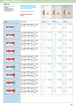
INTERLOCKED PLUG-IN OUTLETS
PRESE INTERBLOCCATE
Spine a selezione di fase
Spine precablate
26
28
Phase selection plugs
Pre-wired plug
DISPOSITIVI DI FISSAGGIO
30
FIXING UNITS
DIMENSIONI
32
DIMENSIONS
CARATTERISTICHE TECNICHE
38
TECHNICAL DATA
INDICAZIONI DI MONTAGGIO
40
ASSEMBLY INSTRUCTIONS
-
MISTRAL INTERNO.indd 1
Straight lengths
End feed units
End covers
Flexible joint
Plug-outlet cover
1 -
06/02/12 10.00
MISTRAL
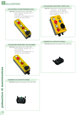
Il condotto della serie MISTRAL, destinato alla
distribuzione di energia per illuminazione e/o
piccola potenza trova applicazione negli insediamenti industriali, commerciali e nel terziario.
Offerto con correnti nominali da 25A, e 40A
(il circuito L4/L5 nella configurazione 6P e
6P+6P è limitato a 25A), i conduttori attivi sono
in rame coestrusi in una guaina in materiale
termoplastico halogen free autoestinguente.
L’involucro (con funzione di conduttore di
protezione) è offerto sia in acciaio zincato a
caldo che in acciaio zincato a caldo plastificato (colore bianco RAL 9016) particolarmente
adatto all’installazione in ambienti aggressivi
(a richiesta sono disponibili colori diversi dallo
standard).
Le configurazioni circuitali sono 2P, 4P, 6P in
un unico involucro e 2P+2P, 4P+2P, 4P+4P e
6P+6P in un doppio involucro che separa meccanicamente i due circuiti su tutta la lunghezza.
Il condotto è proposto in due versioni:
-Prese standard
-Prese interbloccate
Il condotto “Prese standard” è fornito con
le prese di derivazione di colore arancione
(ad eccezione del condotto 4+2), predisposte
lungo l’elemento in quantità variabile di 2, 3
o 6 prese su un lato dell’elemento singolo e
2+2, 3+3, 6+6 prese su entrambi i lati dell’elemento doppio (a richiesta sono disponibili
configurazioni speciali con quantità e interasse
diverso dallo standard). Le spine di derivazione installabili su questa versione sono del tipo
a selezione di fase (con o senza fusibile), o
precablate (con cavo senza fusibile), con l’identificazione cromatica per il riconoscimento
del circuito cablato. Le spine non hanno alcun
vincolo meccanico di montaggio sull’elemento, ad eccezione del condotto 4+2, dove sul
lato a due conduttori può essere creato un interblocco utilizzando le spine LOCK/A (es. utilizzo come circuito d’emergenza).
Il condotto “Prese interbloccate” è fornito
con le prese di derivazione di colore bianco
e/o rosso, predisposte lungo l’elemento in
quantità variabile di 2, 3 o 6 prese su un lato
dell’elemento singolo e 2+2, 3+3, 6+6 prese su
entrambi i lati dell’elemento doppio (a richiesta
sono disponibili configurazioni speciali con
-
MISTRAL INTERNO.indd 2
quantità e interasse diverso dallo standard).
Le spine di derivazione installabili su questa
versione sono del tipo a selezione di fase (con
o senza fusibile), o precablate (con cavo senza
fusibile), con l’identificazione cromatica per il
riconoscimento del circuito cablato. Le spine
hanno un vincolo meccanico di montaggio
sull’elemento; le spine LCK/A (colore rosso)
possono essere installate solo su prese di
colore rosso mentre le spine LCK/B (colore
bianco) possono essere installate solo su
prese di colore bianco. Su questa versione di
condotto possono essere installate anche tutte
le spine della versione “prese standard”.
Il condotto è offerto con grado di protezione IP55 che viene garantito senza l’ausilio di
alcun accessorio; in congiunzione tramite un
giunto ad innesto con manicotto premontato e
nella presa di derivazione grazie ad un particolare in termoplastico con guarnizione costampata che viene rimossa tramite un apposita
linguetta in caso di utilizzo della stessa.
Completano la gamma alimentazioni, chiusure,
e relativi sistemi di fissaggio dei condotti e dei
corpi illuminanti.
2 -
06/02/12 10.00
The MISTRAL bus-bar
trunking system, used to distribute lighting and low power,
is mainly installed in industrial, commercial and
service buildings.
The MISTRAL range rates 25A, and 40A of
nominal ratings (the L4/L5 circuit with 6 or 6+6
conductors rates 25A only).
The active conductors are made of electrolytic
copper; all along their length they are fully insulated by an halogen-free sheet made of selfextinguishing thermoplastic material.
The casing (used as PE conductor as well) is
available either made of hot galvanized steel
or hot galvanized and plasticized steel (white
colour, RAL 9016), being the latter particularly
suitable where resistance to chemical agents
is required (different colours are available on
demand).
The available configurations are 2, 4 and 6 conductors within a single casing, and 2+2, 4+2,
4+4 and 6+6 conductors within a double casing, mechanically separating the two circuits
along the whole length.
The MISTRAL bus-bar trunking system is available in two versions:
- with “standard plug-in outlets”;
- with “inter-locked plug-in outlets”.
The version with “standard plug-in outlets” is
equipped with orange colour plug-in outlets
(except for the 4+2 conductors one), preinstalled along the unit length in the number of
2, 3 or 6 on a single side for the single-casing
element, and 2+2, 3+3, 6+6 on both sides for
the double casing element. Different number of
plug-in outlets, or different distances between
the outlets are available on demand.
The plugs for this version are either phaseselecting plugs (with or without fuse) or prewired plugs (with cable, without fuse). The
plugs have different colours to identify the
pre-wired circuit.
The plugs do not have any mechanical device
to restrain their insertion into the bus-bar
element, except for the 4+2 conductors configuration, where it’s possible to create an
inter-lock on the two conductors side, by using
the LOCK/A plugs (to be used, for instance, as
emergency circuit).
The version with “inter-locked plug-in outlets”
is supplied with white and /or red colour plug-
-
MISTRAL INTERNO.indd 3
in outlets, pre-installed along
the unit length in the number
of 2, 3 or 6 on a single side for
the single-casing element, and 2+2,
3+3, 6+6 on both sides for the double casing element. Different number of plug-in outlets, or different distances between the outlets
are available on demand.
The plugs for this version are either phaseselecting plugs (with or without fuse) or prewired plugs (with cable, without fuse). The
plugs have different colours to identify the
pre-wired circuit.
The plugs have a mechanical device restraining
the insertion into the bus-bar element: the red
colour plugs (LCK/A) can be inserted into the
red colour plug-in outlets only, while the white
colour plugs (LCK/B) can be inserted into the
white colour plug-in outlets only. All the “standard plugs” can be installed on this version, too.
The IP55 protection degree is ensured without
any additional accessory: by a connection joint
having a pre-fitted sleeve, at the connection
point; by a removable plug-in outlet cover,
equipped with a contemporary moulded gasket, at the plug-in outlets position.
Feed units, end covers and mechanical accessories designed for suspending the lines and
fixing the lamps are also available to complete
the system.
3 -
06/02/12 10.00
ACCIAIO ZINCATO A CALDO
PRESE STANDARD
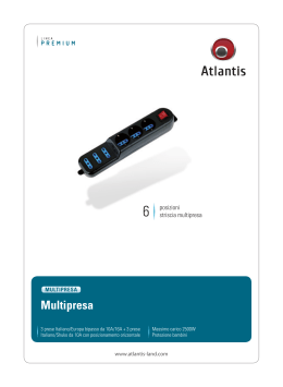
Elemento rettilineo
Utilizzato per la distribuzione di energia elettrica con correnti da 25A e 40A, (il circuito L4/L5
nei condotti a 6 poli e 6+6 poli da 40A è limitato a 25A) è fornito in versione standard IP55
(senza alcuna aggiunta di accessori).
L’involucro (utilizzato come conduttore di protezione) è realizzato in lamiera di acciaio zincata a caldo. Le configurazioni disponibili sono
2P, 4P e 6P in un unico involucro, e 2P+2P,
4P+2P, 4P+4P e 6P+6P in un doppio involucro
con i due circuiti meccanicamente separati su
tutta la lunghezza.
L’elemento è fornito con le prese di derivazione di colore arancione (ad eccezione del
condotto 4+2), predisposte lungo l’elemento
in quantità variabile di 2, 3 o 6 prese su un
solo lato dell’elemento singolo e 2+2, 3+3,
6+6 prese su entrambi i lati dell’elemento doppio (a richiesta sono disponibili configurazioni
speciali con quantità e interasse diverso dallo
standard). Le spine di derivazione installabili
su questa versione sono del tipo a selezione
di fase (con o senza fusibile) o precablate
(con cavo senza fusibile), con l’identificazione
cromatica per il riconoscimento del circuito
cablato. Le spine non hanno alcun vincolo
meccanico di montaggio sull’elemento, ad
eccezione del condotto 4+2, dove sul lato a
due conduttori può essere creato un interblocco utilizzando le spine LOCK/A (es. utilizzo
come circuito d’emergenza).
Le lunghezze standard sono 3, 2 e 1,5 metri
e a richiesta possono essere forniti elementi
con lunghezze diverse dallo standard o con le
prese di derivazione in posizione e/o quantità
diversa dallo standard.
Straight elements
IP55
Senza aggiungere accessori
Without adding accessories
caratteristiche tecniche
technical data
pg.38
dimensioni
dimensions
pg.32
Singolo
Single
Used to distribute electric power with nominal
ratings of 25A and 40A (the L4/L5 circuit of
the elements with 6 or 6+6 conductors, from
40A, rates 25A only), the straight element is
ensuring the IP55 protection degree in its standard version already (without any additional
accessory).
The casing (used as Pe conductor as well) is
made of hot galvanized steel sheet.
The available configurations are 2, 4 and 6
conductors within a single casing, and 2+2,
4+2, 4+4 and 6+6 conductors within a double
casing, mechanically separating the two circuits along the whole length.
The straight element is equipped with orange colour plug-in outlets (except for the 4+2
conductors one), pre-installed along the unit
length in the number of 2, 3 or 6 on a single
side for the single-casing element, and 2+2,
3+3, 6+6 on both sides for the double casing
element. Different number of plug-in outlets,
or different distances between the outlets are
available on demand.
The plugs for this version are either phaseselecting plugs (with or without fuse) or prewired plugs (with cable, without fuse). The
plugs have different colours to identify the
pre-wired circuit.
The plugs do not have any mechanical device to restrain their insertion into the bus-bar
element, except for the 4+2 conductors configuration, where it’s possible to create an
inter-lock on the two conductors side, by using
the LOCK/A plugs (to be used, for instance, as
emergency circuit).
The standard lengths of the elements are: 3
m., 2 m. and 1,5 m.; different lengths, different
number of plug-in outlets, or different intervals
between the outlets are available on demand.
Doppio
Double
-
MISTRAL INTERNO.indd 4
4 -
06/02/12 10.00
HOT GALVANIZED STEEL
STANDARD PLUG-IN OUTLETS
Pe
Pe
L3
N
25A
Lunghezza [m]
Lenght [m]
n. derivazioni
n. tap-off
3
3
3
2
1,5
speciale - special
2
3
6
2
2
40A
**
Lunghezza [m]
Lenght [m]
n. derivazioni
n. tap-off
3
3
3
2
1,5
speciale - special
2
3
6
2
2
**
Pe
L3
L2
L1
N
L3
N2
}
L4
L3
L2
L1
N
L5
Pe
L3
N2
}
Pe
L3
N
N
L3
2P
4P
6P
2P + 2P
MI25S2
MI25S4
MI25S6*
MIC25A13HAZ
MIC25A14HAZ
MIC25A15HAZ
MIC25A16HAZ
MIC25A17HAZ
MIC25A18HAZ
MIC25A13AAZ
MIC25A14AAZ
MIC25A15AAZ
MIC25A16AAZ
MIC25A17AAZ
MIC25A18AAZ
MI40S2
MIC40A13HAZ
MIC40A14HAZ
MIC40A15HAZ
MIC40A16HAZ
MIC40A17HAZ
MIC40A18HAZ
L3
N2
{
Pe
Pe
L3
L2
L1
N
N
L3
N2
{
L3
Pe
Pe
L3
L2
L1
N
N
L1
L2
L3
{
}N2L3
Pe
L3
N2
L4
L3
L2
L1
N
L5
L5
N
L1
L2
L3
L4
6P + 6P
N2
L3
Pe
}
4P + 2P (LCKA)
4P + 4P
MI25D22
MI25D42
MI25D44
MI25D66*
MIC25A13LAZ
MIC25A14LAZ
MIC25A15LAZ
MIC25A16LAZ
MIC25A17LAZ
MIC25A18LAZ
MIC25A03MAZ
MIC25A04MAZ
MIC25A05MAZ
MIC25A06MAZ
MIC25A07MAZ
MIC25A08MAZ
MIC25A03NAZ
MIC25A04NAZ
MIC25A05NAZ
MIC25A06NAZ
MIC25A07NAZ
MIC25A08NAZ
MIC25A03PAZ
MIC25A04PAZ
MIC25A05PAZ
MIC25A06PAZ
MIC25A07PAZ
MIC25A08PAZ
MIC25A03QAZ
MIC25A04QAZ
MIC25A05QAZ
MIC25A06QAZ
MIC25A07QAZ
MIC25A08QAZ
MI40S4
MI40S6*
MI40D22
MI40D42
MI40D44
MI40D66*
MIC40A13AAZ
MIC40A14AAZ
MIC40A15AAZ
MIC40A16AAZ
MIC40A17AAZ
MIC40A18AAZ
MIC40A13LAZ
MIC40A14LAZ
MIC40A15LAZ
MIC40A16LAZ
MIC40A17LAZ
MIC40A18LAZ
MIC40A03MAZ
MIC40A04MAZ
MIC40A05MAZ
MIC40A06MAZ
MIC40A07MAZ
MIC40A08MAZ
MIC40A03NAZ
MIC40A04NAZ
MIC40A05NAZ
MIC40A06NAZ
MIC40A07NAZ
MIC40A08NAZ
MIC40A03PAZ
MIC40A04PAZ
MIC40A05PAZ
MIC40A06PAZ
MIC40A07PAZ
MIC40A08PAZ
MIC40A03QAZ
MIC40A04QAZ
MIC40A05QAZ
MIC40A06QAZ
MIC40A07QAZ
MIC40A08QAZ
i
Per configurazioni speciali
prego contattare nostro
ufficio tecnico.
For custom-made
solutions please contact
our technical department.
*
Il circuito L4/L5 è
limitato a 25A anche nelle
versioni di blindo da 40A
The L4/L5 circuit only rates 25A
even for the 40A
bus-bar trunking units.
**
Da definire in base
alla lunghezza
To define according
to the lenght
Colore presa
di derivazione
Plug-in
outlet color
5
MISTRAL INTERNO.indd 5
06/02/12 10.00
ACCIAIO ZINCATO A CALDO
PRESE STANDARD
Alimentazione
Feed units
Utilizzata per alimentare il condotto ad inizio
linea è fornita in versione destra o sinistra in
base al lato di connessione sull’elemento rettilineo (versione dx senza manicotto, versione
sx con manicotto).
L’involucro è in materiale termoplastico, mentre il tratto di condotto è in lamiera di acciaio
zincata a caldo.
Nella versione doppia i due circuiti sono meccanicamente separati su tutta la lunghezza.
Singola
Single
IP55
Senza aggiungere accessori
Without adding accessories
caratteristiche tecniche
technical data
pg.38
dimensioni
dimensions
pg.33
Doppia
Double
Destra
Right
Destra
Right
Sinistra
Left
Sinistra
Left
Testata di chiusura
Utilizzata per chiudere il condotto a fine linea
è fornita in versione destra o sinistra in base
al lato di connessione sull’elemento rettilineo (chiusura destra se la linea inizia con un
alimentazione sinistra o chiusura sinistra se
la linea inizia con un alimentazione destra).
L’involucro della chiusura destra viene fornito
in materiale termoplastico con un tratto di condotto in lamiera di acciaio zincato a caldo. La
chiusura sinistra è in materiale termoplastico e
può essere utilizzata sia sulle linee in acciaio
zincato che plastificato.
End covers
IP55
Senza aggiungere accessori
Without adding accessories
caratteristiche tecniche
technical data
pg.38
dimensioni
dimensions
pg.33
Singola
Single
Doppia
Double
Sinistra
Left
Sinistra
Left
Destra
Right
Destra
Right
-
MISTRAL INTERNO.indd 6
The feed units are used to feed the line; they
are available in right (RH) and left (LH) versions,
to be connected with the correspondent end of
the straight element (the RH version, without
sleeve; the LH version, with sleeve).
The casing is made of thermoplastic material,
while the trunk is made of hot galvanized steel
sheet.
For the double-casing elements, the two circuits are mechanically separated along the
whole length.
Used to close the end of each line, the end
covers are available in right (RH) and left (LH)
versions, to be connected with the correspondent end of the straight element (RH end
cover, in case the line starts with a LH feed
unit; LH end cover, in case the line starts with
a RH feed unit).
For the RH end cover, the casing is made of
thermoplastic material, with a part of trunk
made of hot galvanized steel sheet.
The LH end cover is made of thermoplastic
material and is suitable for both galvanized and
plasticized lines.
6 -
06/02/12 10.00
HOT GALVANIZED STEEL
STANDARD PLUG-IN OUTLETS
Pe
Pe
L3
L3
N2
{
N
25A
DX - RH
SX - LH
40A
DX - RH
SX - LH
(1)
(2)
L4
L3
L2
L1
N
L5
L3
N2
}
{
Pe
L3
N2
}
Pe
L3
N
N
L3
4P
6P
2P + 2P
MI25S2
MI25S4
MI25S6*
MIC32V01AAZ
MIC32V02AAZ
MIC32V01AAZ
MIC32V02AAZ
MI40S2
MIC40V01AAZ
MIC40V02AAZ
{
Pe
Pe
L3
L2
L1
N
L3
N2
N
L3
N2
{
L3
Pe
Pe
L3
L2
L1
N
N
L1
L2
L3
L3
N2
{
} N2L3
Pe
L4
L3
L2
L1
N
L5
L5
N
L1
L2
L3
L4
}
4P + 4P
MI25D22
MI25D42
MI25D44
MI25D66*
MIC32V01LAZ
MIC32V02LAZ
MIC32V01PAZ
MIC32V02PAZ
MIC32V01PAZ
MIC32V02PAZ
MIC32V01PAZ
MIC32V02PAZ
MIC32V01QAZ
MIC32V02QAZ
MI40S4
MI40S6*
MI40D22
MI40D42
MI40D44
MI40D66*
MIC40V01AAZ
MIC40V02AAZ
MIC40V01LAZ
MIC40V02LAZ
MIC40V01PAZ
MIC40V02PAZ
MIC40V01PAZ
MIC40V02PAZ
MIC40V01PAZ
MIC40V02PAZ
MIC40V01QAZ
MIC40V02QAZ
Pe
L4
L3
L2
L1
N
L5
Pe
Pe
N
L3
L2
L1
N
2P
4P
6P
2P + 2P
MI - - S2
MI - - S4
MI - - S6*
MIC40Y01AAZ
MIC40Y02AAA
MIC40Y01AAZ
MIC40Y02AAA
MIC40Y01AAZ
MIC40Y02AAA
L3
N2
}
L3
N2
}
L3
N
N
L3
{
L3
N2
Pe
Pe
L3
L2
L1
N
N
L3
N2
{
L3
6P + 6P
N2
L3
Pe
4P + 2P (LCKA)
Pe
L3
DX - RH
SX - LH
L3
N2
2P
Pe
25-40A
Pe
L3
L2
L1
N
Pe
L3
L2
L1
N
N
L1
L2
L3
L3
N2
{
}N2L3
Pe
Pe
L4
L3
L2
L1
N
L5
L5
N
L1
L2
L3
L4
}N2L3
Pe
4P + 2P (LCKA)
4P + 4P
6P + 6P
MI - - D22
MI - - D42
MI - - D44
MI - - D66*
MIC40Y01PAZ
MIC40Y02PAA
MIC40Y01PAZ
MIC40Y02PAA
MIC40Y01PAZ
MIC40Y02PAA
MIC40Y01PAZ
MIC40Y02PAA
i
(1) Da utilizzare quando la
linea inizia con una
alimentazione SX
To be used when the line
starts with a LH feed unit
(2) Da utilizzare quando la
linea inizia con una
alimentazione DX
To be used when the line
starts with a RH feed unit
*
Il circuito L4/L5 è
limitato a 25A anche nelle
versioni di blindo da 40A
The L4/L5 circuit only rates 25A
even for the 40A
bus-bar trunking units.
-
MISTRAL INTERNO.indd 7
Colore presa
di derivazione
Plug-in
outlet color
7 -
06/02/12 10.00
ACCIAIO ZINCATO A CALDO
PRESE STANDARD
Giunto flessibile
Flexible joint
IP55
Senza aggiungere accessori
Utilizzato per realizzare cambi di direzione o
per evitare eventuali ostacoli lungo il percorso del condotto. L’involucro è in materiale
termoplastico, mentre il tratto di condotto è
realizzato in lamiera di acciaio zincata a caldo.
Nella versione doppia i due circuiti sono meccanicamente separati su tutta la lunghezza.
Singolo
Single
Without adding accessories
caratteristiche tecniche
technical data
pg.38
dimensioni
dimensions
pg.34
Doppio
Double
Otturatore
Utilizzato per ripristinare il grado di protezione
IP55 delle prese di derivazione precedentemente
utilizzate.
Plug-in outlet cover
IP55
Senza aggiungere accessori
Without adding accessories
caratteristiche tecniche
technical data
pg.38
dimensioni
dimensions
pg.34
-
MISTRAL INTERNO.indd 8
It enables line direction changes and is also
used to overcome obstacles along the run. The
casing is made of thermoplastic material, while
the trunk is made of hot galvanized steel sheet.
For the double-casing elements the two circuits are mechanically separated along the
whole length.
The plug-in outlet cover is installed to restore
the original IP55 protection degree of the previously used plug-in outlets.
8 -
06/02/12 10.00
HOT GALVANIZED STEEL
STANDARD PLUG-IN OUTLETS
Pe
Pe
L3
N
25A
40A
L4
L3
L2
L1
N
L5
L3
N2
}
Pe
L3
N2
}
Pe
L3
N
N
L3
{
L3
N2
Pe
L3
L2
L1
N
N
L3
N2
{
L3
Pe
L3
L2
L1
N
N
L1
L2
L3
Pe
Pe
L3
N2
{
N2
L3
Pe
}
L4
L3
L2
L1
N
L5
L5
N
L1
L2
L3
L4
N2
L3
Pe
}
2P
4P
6P
2P + 2P
4P + 2P (LCKA)
4P + 4P
6P + 6P
MI25S2
MI25S4
MI25S6*
MI25D22
MI25D42
MI25D44
MI25D66*
MIC32C21AAZ
MIC32C21AAZ
MIC32C21LAZ
MIC32C21PAZ
MIC32C21PAZ
MIC32C21PAZ
MIC32C21QAZ
MI40S2
MI40S4
MI40S6*
MI40D22
MI40D42
MI40D44
MI40D66*
MIC40C21AAZ
MIC40C21AAZ
MIC40C21LAZ
MIC40C21PAZ
MIC40C21PAZ
MIC40C21PAZ
MIC40C21QAZ
Pe
Pe
L3
N
25-40A
Pe
L3
L2
L1
N
Pe
L3
L2
L1
N
L4
L3
L2
L1
N
L5
L3
N2
}
Pe
}
L3
N2
Pe
L3
N
N
L3
2P
4P
6P
2P + 2P
MI - - S2
MI - - S4
MI - - S6*
MIX00001AAA
MIX00001AAA
MIX00001AAA
L3
N2
{
Pe
Pe
L3
L2
L1
N
N
L3
N2
{
L3
Pe
L3
L2
L1
N
N
L1
L2
L3
Pe
L3
N2
{
N2
L3
Pe
}
L4
L3
L2
L1
N
L5
L5
N
L1
L2
L3
L4
N2
L3
Pe
}
4P + 2P (LCKA)
4P + 4P
6P + 6P
MI - - D22
MI - - D42
MI - - D44
MI - - D66*
MIX00001AAA
MIX00001AAA
MIX00001AAA
MIX00001AAA
i
*
Il circuito L4/L5 è
limitato a 25A anche nelle
versioni di blindo da 40A
Colore presa
di derivazione
Plug-in
outlet color
The L4/L5 circuit only rates 25A
even for the 40A
bus-bar trunking units.
-
MISTRAL INTERNO.indd 9
9 -
06/02/12 10.00
ACCIAIO PLASTIFICATO
PRESE STANDARD
Elemento rettilineo
Utilizzato per la distribuzione di energia elettrica con correnti da 25A e 40A, (il circuito L4/L5
nei condotti a 6 poli e 6+6 poli da 40A è limitato a 25A) è fornito in versione standard IP55
(senza alcuna aggiunta di accessori).
L’involucro (utilizzato come conduttore di protezione) è realizzato in lamiera di acciaio zincata a caldo plastificato ( bianco RAL 9016 ).
A richiesta sono disponibili colori diversi dallo
standard. Le configurazioni disponibili sono
2P, 4P e 6P in un unico involucro, e 2P+2P,
4P+2P, 4P+4P e 6P+6P in un doppio involucro
con i due circuiti meccanicamente separati su
tutta la lunghezza. L’elemento è fornito con
le prese di derivazione di colore arancione
(ad eccezione del condotto 4+2), predisposte
lungo l’elemento in quantità variabile di 2, 3 o
6 prese su un solo lato dell’elemento singolo
e 2+2, 3+3, 6+6 prese su entrambi i lati dell’elemento doppio (a richiesta sono disponibili
configurazioni speciali con quantità e interasse
diverso dallo standard). Le spine di derivazione
installabili su questa versione sono del tipo a
selezione di fase (con o senza fusibile) o precablate (con cavo senza fusibile), con l’identificazione cromatica per il riconoscimento del
circuito cablato. Le spine non hanno alcun vincolo meccanico di montaggio sull’elemento,
ad eccezione del condotto 4+2, dove sul lato a
due conduttori può essere creato un interblocco meccanico utilizzando le spine LOCK/A (es.
utilizzo come circuito d’emergenza).
Le lunghezze standard sono 3, 2 e 1,5 metri
A richiesta possono essere forniti elementi
con lunghezze diverse dallo standard o con le
prese di derivazione in posizione e/o quantità
diversa dallo standard.
Straight elements
IP55
Senza aggiungere accessori
Without adding accessories
caratteristiche tecniche
technical data
pg.38
dimensioni
dimensions
pg.32
Singolo
Single
Used to distribute electric power with nominal
ratings of 25A and 40A (the L4/L5 circuit of the
elements with 6 or 6+6 conductors, from 40A,
rates 25A only), the straight element is ensuring the IP55 protection degree in its standard
version already (without any additional accessory).
The casing (used as Pe conductor as well) is
made of plasticized hot galvanized steel sheet
(white colour, RAL 9016). Different colours are
available on demand.
The available configurations are 2, 4 and 6 conductors within a single casing, and 2+2, 4+2,
4+4 and 6+6 conductors within a double casing, mechanically separating the two circuits
along the whole length.
The straight element is equipped with orange
colour plug-in outlets (except for the 4+2
conductors one), pre-installed along the unit
length in the number of 2, 3 or 6 on a single
side for the single-casing element, and 2+2,
3+3, 6+6 on both sides for the double casing
element. Different number of plug-in outlets,
or different distances between the outlets are
available on demand.
The plugs for this version are either phaseselecting plugs (with or without fuse) or prewired plugs (with cable, without fuse). The
plugs have different colours to identify the
pre-wired circuit.
The plugs do not have any mechanical device
to restrain their insertion into the bus-bar
element, except for the 4+2 conductors configuration, where it’s possible to create an
inter-lock on the two conductors side, by using
the LOCK/A plugs (to be used, for instance, as
emergency circuit).
The standard lengths of the elements are: 3
m., 2 m. and 1,5 m.; different lengths, different
number of plug-in outlets, or different intervals
between the outlets are available on demand.
Doppio
Double
-
MISTRAL INTERNO.indd 10
10 -
06/02/12 10.00
PLASTICIZED STEEL
STANDARD PLUG-IN OUTLETS
Pe
Pe
L3
N
25A
Lunghezza [m]
Lenght [m]
n. derivazioni
n. tap-off
3
3
3
2
1,5
speciale - special
2
3
6
2
2
40A
**
Lunghezza [m]
Lenght [m]
n. derivazioni
n. tap-off
3
3
3
2
1,5
speciale - special
2
3
6
2
2
**
Pe
L3
L2
L1
N
L3
N2
}
Pe
L4
L3
L2
L1
N
L5
L3
N2
}
Pe
L3
N
N
L3
2P
2P
4P
4P
6P
6P
2P ++ 2P
2P
2P
MI25S2
MI25S4
MI25S6*
MIC25A13HAA
MIC25A14HAA
MIC25A15HAA
MIC25A16HAA
MIC25A17HAA
MIC25A18HAA
MIC25A13AAA
MIC25A14AAA
MIC25A15AAA
MIC25A16AAA
MIC25A17AAA
MIC25A18AAA
MI40S2
MIC40A13HAA
MIC40A14HAA
MIC40A15HAA
MIC40A16HAA
MIC40A17HAA
MIC40A18HAA
L3
N2
{
Pe
Pe
Pe
L3
L2
L1
N
N
L3
L3
N2
N2
{
L3
Pe
Pe
Pe
L3
L3
L2
L2
L1
L1
NN
NN
L1
L1
L2
L2
L3
L3
L3
L3
N2
N2
{
N2
N2
L3L3
Pe
Pe
}
L4
L4
L3
L3
L2
L2
L1
L1
NN
L5
L5
L5
L5
NN
L1
L1
L2
L2
L3
L3
L4
L4
6P ++ 6P
6P
6P
N2
N2
L3
L3
Pe
Pe
}
4P ++ 2P
2P (LCKA)
(LCKA)
4P
4P
4P ++ 4P
4P
MI25D22
MI25D42
MI25D44
MI25D66*
MIC25A13LAA
MIC25A14LAA
MIC25A15LAA
MIC25A16LAA
MIC25A17LAA
MIC25A18LAA
MIC25A03MAA
MIC25A04MAA
MIC25A05MAA
MIC25A06MAA
MIC25A07MAA
MIC25A08MAA
MIC25A03NAA
MIC25A04NAA
MIC25A05NAA
MIC25A06NAA
MIC25A07NAA
MIC25A08NAA
MIC25A03PAA
MIC25A04PAA
MIC25A05PAA
MIC25A06PAA
MIC25A07PAA
MIC25A08PAA
MIC25A03QAA
MIC25A04QAA
MIC25A05QAA
MIC25A06QAA
MIC25A07QAA
MIC25A08QAA
MI40S4
MI40S6*
MI40D22
MI40D42
MI40D44
MI40D66*
MIC40A13AAA
MIC40A14AAA
MIC40A15AAA
MIC40A16AAA
MIC40A17AAA
MIC40A18AAA
MIC40A13LAA
MIC40A14LAA
MIC40A15LAA
MIC40A16LAA
MIC40A17LAA
MIC40A18LAA
MIC40A03MAA
MIC40A04MAA
MIC40A05MAA
MIC40A06MAA
MIC40A07MAA
MIC40A08MAA
MIC40A03NAA
MIC40A04NAA
MIC40A05NAA
MIC40A06NAA
MIC40A07NAA
MIC40A08NAA
MIC40A03PAA
MIC40A04PAA
MIC40A05PAA
MIC40A06PAA
MIC40A07PAA
MIC40A08PAA
MIC40A03QAA
MIC40A04QAA
MIC40A05QAA
MIC40A06QAA
MIC40A07QAA
MIC40A08QAA
i
Per configurazioni speciali
prego contattare nostro
ufficio tecnico.
For custom-made
solutions please contact
our technical department.
*
Il circuito L4/L5 è
limitato a 25A anche nelle
versioni di blindo da 40A
The L4/L5 circuit only rates 25A
even for the 40A
bus-bar trunking units.
**
Da definire in base
alla lunghezza
To define according
to the lenght
-
MISTRAL INTERNO.indd 11
Colore presa
di derivazione
Plug-in
outlet color
11 -
06/02/12 10.00
ACCIAIO PLASTIFICATO
PRESE STANDARD
Alimentazione
Feed units
Utilizzata per alimentare il condotto ad inizio
linea è fornita in versione destra o sinistra in
base al lato di connessione sull’elemento rettilineo (versione dx senza manicotto, versione
sx con manicotto).
L’involucro è in materiale termoplastico, mentre il tratto di condotto è in lamiera di acciaio
zincata a caldo plastificata (colore Bianco RAL
9016). Nella versione doppia i due circuiti sono
meccanicamente separati su tutta la lunghezza.
Singola
Single
IP55
Senza aggiungere accessori
Without adding accessories
caratteristiche tecniche
technical data
pg.38
dimensioni
dimensions
pg.33
Doppia
Double
Destra
Right
Destra
Right
Sinistra
Left
Sinistra
Left
Testata di chiusura
Utilizzata per chiudere il condotto a fine linea
è fornita in versione destra o sinistra in base
al lato di connessione sull’elemento rettilineo (chiusura destra se la linea inizia con un
alimentazione sinistra o chiusura sinistra se
la linea inizia con un alimentazione destra).
L’involucro della chiusura destra viene fornito
in materiale termoplastico con un tratto di
condotto in lamiera di acciaio zincato a caldo
plastificata (colore Bianco RAL 9016). La chiusura sinistra è in materiale termoplastico e
può essere utilizzata sia sulle linee in acciaio
zincato che plastificato.
End cover
IP55
Senza aggiungere accessori
Without adding accessories
caratteristiche tecniche
technical data
pg.38
dimensioni
dimensions
pg.33
Singola
Single
Doppia
Double
Sinistra
Left
Sinistra
Left
Destra
Right
Destra
Right
-
MISTRAL INTERNO.indd 12
The feed units are used to feed the line; they
are available in right (RH) and left (LH) versions,
to be connected with the correspondent end of
the straight element (the RH version, without
sleeve; the LH version, with sleeve).
The casing is made of thermoplastic material,
while the trunk is made of plasticized, hot galvanized steel sheet (white colour, RAL 9016).
For the double-casing elements, the two circuits are mechanically separated along the
whole length.
Used to close the end of each line, the end
covers are available in right (RH) and left
(LH) versions, to be connected with the
correspondent end of the straight element
(RH end cover, in case the line starts with a
LH feed unit; LH end cover, in case the line
starts with a RH feed unit).
For the RH end cover, the casing is made of
thermoplastic material, with a part of trunk
made of plasticized, hot galvanized steel sheet
(white colour, RAL 9016).
The LH end cover is made of thermoplastic
material and is suitable for both galvanized and
plasticized lines.
12 -
06/02/12 10.00
PLASTICIZED STEEL
STANDARD PLUG-IN OUTLETS
Pe
Pe
L3
N
25A
DX - RH
SX - LH
40A
DX - RH
SX - LH
(1)
(2)
}
Pe
L4
L3
L2
L1
N
L5
L3
N2
}
Pe
L3
N
N
L3
4P
6P
2P + 2P
MI25S2
MI25S4
MI25S6*
MIC32V01AAA
MIC32V02AAA
MIC32V01AAA
MIC32V02AAA
MI40S2
MIC40V01AAA
MIC40V02AAA
{
Pe
Pe
L3
L2
L1
N
L3
N2
N
L3
N2
{
L3
Pe
Pe
L3
L2
L1
N
N
L1
L2
L3
L3
N2
{
N2
L3
Pe
}
L4
L3
L2
L1
N
L5
L5
N
L1
L2
L3
L4
}
4P + 4P
MI25D22
MI25D42
MI25D44
MI25D66*
MIC32V01LAA
MIC32V02LAA
MIC32V01PAA
MIC32V02PAA
MIC32V01PAA
MIC32V02PAA
MIC32V01PAA
MIC32V02PAA
MIC32V01QAA
MIC32V02QAA
MI40S4
MI40S6*
MI40D22
MI40D42
MI40D44
MI40D66*
MIC40V01AAA
MIC40V02AAA
MIC40V01LAA
MIC40V02LAA
MIC40V01PAA
MIC40V02PAA
MIC40V01PAA
MIC40V02PAA
MIC40V01PAA
MIC40V02PAA
MIC40V01QAA
MIC40V02QAA
Pe
Pe
L4
L3
L2
L1
N
L5
Pe
Pe
6P + 6P
N2
L3
Pe
4P + 2P (LCKA)
Pe
L3
DX - RH
SX - LH
L3
N2
2P
Pe
25-40A
Pe
L3
L2
L1
N
Pe
L4
L3
L2
L1
N
L5
L5
N
L1
L2
L3
L4
N
L3
L2
L1
N
2P
4P
6P
2P + 2P
4P + 2P (LCKA)
4P + 4P
6P + 6P
MI - - S2
MI - - S4
MI - - S6*
MI - - D22
MI - - D42
MI - - D44
MI - - D66*
MIC40Y01AAA
MIC40Y02AAA
MIC40Y01AAA
MIC40Y02AAA
MIC40Y01AAA
MIC40Y02AAA
MIC40Y01PAA
MIC40Y02PAA
MIC40Y01PAA
MIC40Y02PAA
MIC40Y01PAA
MIC40Y02PAA
MIC40Y01PAA
MIC40Y02PAA
L3
N2
}
L3
N2
}
L3
N
N
L3
L3
N2
{
Pe
L3
L2
L1
N
N
L3
N2
{
L3
L3
L2
L1
N
N
L1
L2
L3
Pe
L3
N2
{
}N2L3
Pe
}N2L3
Pe
i
(1) Da utilizzare quando la
linea inizia con una
alimentazione SX
To be used when the line
starts with a LH feed unit
(2) Da utilizzare quando la
linea inizia con una
alimentazione DX
To be used when the line
starts with a RH feed unit
*
Il circuito L4/L5 è
limitato a 25A anche nelle
versioni di blindo da 40A
The L4/L5 circuit only rates 25A
even for the 40A
bus-bar trunking units.
-
MISTRAL INTERNO.indd 13
Colore presa
di derivazione
Plug-in
outlet color
13 -
06/02/12 10.00
ACCIAIO PLASTIFICATO
PRESE STANDARD
Giunto flessibile
Flexible joint
IP55
Senza aggiungere accessori
Utilizzato per realizzare cambi di direzione o
per evitare eventuali ostacoli lungo il percorso del condotto. L’involucro è in materiale
termoplastico, mentre il tratto di condotto è
realizzato in lamiera di acciaio zincata a caldo
plastificata (colore Bianco RAL 9016). Nella
versione doppia i due circuiti sono meccanicamente separati su tutta la lunghezza.
Singolo
Single
Without adding accessories
caratteristiche tecniche
technical data
pg.38
dimensioni
dimensions
pg.34
Doppio
Double
Otturatore
Utilizzato per ripristinare il grado di protezione
IP55 delle prese di derivazione precedentemente
utilizzate.
Plug-in outlet cover
IP55
Senza aggiungere accessori
Without adding accessories
caratteristiche tecniche
technical data
pg.38
dimensioni
dimensions
pg.34
-
MISTRAL INTERNO.indd 14
It enables line direction changes and is also
used to overcome obstacles along the run. The
casing is made of thermoplastic material, while
the trunk is made of plasticized, hot galvanized
steel sheet (white colour, RAL 9016).
For the double-casing elements the two circuits are mechanically separated along the
whole length.
The plug-in outlet cover is installed to restore
the original IP55 protection degree of the previously used plug-in outlets.
14 -
06/02/12 10.00
PLASTICIZED STEEL
STANDARD PLUG-IN OUTLETS
Pe
Pe
L3
N
25A
40A
}
L3
N2
Pe
L4
L3
L2
L1
N
L5
}L3N2
Pe
L3
N
N
L3
Pe
L3
L2
L1
N
{
L3
N2
N
{
L3
N2
L3
Pe
L3
L2
L1
N
N
L1
L2
L3
Pe
Pe
{
}
N2
L3
Pe
L3
N2
L4
L3
L2
L1
N
L5
L5
N
L1
L2
L3
L4
N2
L3
Pe
}
2P
4P
6P
2P + 2P
4P + 2P (LCKA)
4P + 4P
6P + 6P
MI25S2
MI25S4
MI25S6*
MI25D22
MI25D42
MI25D44
MI25D66*
MIC32C21AAA
MIC32C21AAA
MIC32C21LAA
MIC32C21PAA
MIC32C21PAA
MIC32C21PAA
MIC32C21QAA
MI40S2
MI40S4
MI40S6*
MI40D22
MI40D42
MI40D44
MI40D66*
MIC40C21AAA
MIC40C21AAA
MIC40C21LAA
MIC40C21PAA
MIC40C21PAA
MIC40C21PAA
MIC40C21QAA
Pe
Pe
L3
N
25-40A
Pe
L3
L2
L1
N
Pe
L3
L2
L1
N
L3
N2
}
Pe
L4
L3
L2
L1
N
L5
L3
N2
}
Pe
L3
N
N
L3
2P
4P
6P
2P + 2P
MI - - S2
MI - - S4
MI - - S6*
MIX00001AAA
MIX00001AAA
MIX00001AAA
L3
N2
{
Pe
Pe
L3
L2
L1
N
N
L3
N2
{
L3
Pe
Pe
L3
L2
L1
N
N
L1
L2
L3
L3
N2
{
}N2L3
Pe
L4
L3
L2
L1
N
L5
L5
N
L1
L2
L3
L4
}
N2
L3
Pe
4P + 2P (LCKA)
4P + 4P
6P + 6P
MI - - D22
MI - - D42
MI - - D44
MI - - D66*
MIX00001AAA
MIX00001AAA
MIX00001AAA
MIX00001AAA
i
*
Il circuito L4/L5 è
limitato a 25A anche nelle
versioni di blindo da 40A
Colore presa
di derivazione
Plug-in
outlet color
The L4/L5 circuit only rates 25A
even for the 40A
bus-bar trunking units.
-
MISTRAL INTERNO.indd 15
15 -
06/02/12 10.00
PER LE VERSIONI MISTRAL
PRESE STANDARD
Spina a selezione di fase (2P+Pe)
SPINA A SELEZIONE DI FASE (2P+Pe)
Spina monofase disponibile da 16A senza fusibili, da 10A con fusibile da 6,3A e da 16A con
fusibile da 16A. La spina può inoltre essere
fornita con i due contatti L4/L5 (da applicare
sui condotti 6P e 6P+6P).
La selezione delle fasi permette di cablare
circuiti trifase con neutro comune (N/L1, N/L2,
N/L3) o circuiti monofase con neutro separato
(N/L1, N2/L3).
Fornita di base con un contatto neutro e
un contatto fase, inserendo i contatti mobili
supplementari la spina può alimentare carichi
trifase. La spina ha il coperchio trasparente
per identificare i poli selezionati e può essere
installata su tutte le prese di derivazione dei
condotti sia a prese standard che a prese
interbloccate.
16A phase selection plug
IP55
Senza aggiungere accessori
Without adding accessories
caratteristiche tecniche
technical data
pg.38
dimensioni
dimensions
pg.35
It is a single-phase plug, available in the following versions: 16A without fuses; 10A with 6,3A
fuse; 16A with 16A fuse.
The plug can be equipped with the two L4/L5
contacts, too (to be applied on the 6 conductors and 6+6 conductors lines).
The phase selection allows to wire either threephases circuits having a common Neutral (N/
L1, N/L2, N/L3) or single-phase circuits having
separated Neutral (N/L1, N2/L3).
The standard plugs are supplied equipped with
a Neutral contact and a phase contact, but, by
the insertion of extra mobile contacts, they can
be used as three-phases plugs, too.
The plugs have a transparent top, designed to
facilitate the poles selections; they can be used
with both standard and inter-locked plug-in
outlets.
Contatto mobile
Mobile contacts 10A
Disponibile da 16A senza fusibile (di colore
BLU per il NEUTRO o di colore NERO per la
FASE), da 10A con fusibile da 6,3A e da 16A
con fusibile da 16A. Da inserire nella spina a
selezione di fase per derivare carichi trifase.
Designed to be inserted into the phase selecting plugs to feed three-phases circuits, mobile
contacts are available in the following versions:
16A without fuse (blue colour for the Neutral;
black colour for the phase); 10A with 6,3A fuse;
16A with 16A fuse.
Contatto mobile 16A
16A mobile contact
Contatto mobile 16A
16A mobile contact
Contatto mobile 10A
10A mobile contact
Contatto mobile 16A
16A mobile contact
Neutro
Neutral
Fase
Phase
Fase-Fusibile 6,3A (5 x 20)
Phase-fuse 6,3A (5 x 20)
Fase-Fusibile16A CH8 (8,5 x 31,5)
Phase-fuse 16A CH8 (8,5 x 31,5)
-
MISTRAL INTERNO.indd 16
16 -
06/02/12 10.00
FOR MISTRAL RANGE
STANDARD PLUG-IN OUTLETS
Pe
Pe
L3
N
Pe
L3
L2
L1
N
}
L3
N2
Pe
L4
L3
L2
L1
N
L5
}
L3
N2
Pe
L3
N
N
L3
Senza cavo
Without cable
2P
4P
6P
2P + 2P
25-40A
MI - - S2
MI - - S4
MI - - S6
MIX00W50AAA
MIX00W80AAA
MIX00W82AAA
-
MIX00W50AAA
MIX00W80AAA
MIX00W82AAA
-
MIX00W50AAA
MIX00W51AAA
MIX00W80AAA
MIX00W82AAA
MIX00W84AAA
MIX00W85AAA
Portata Fase
Rating Phase
16A
16A
10A
16A
10A
16A
N/L
N/L
N/L
N/L
N/L
N/L
{
L3
N2
Pe
Pe
L3
L2
L1
N
N
{
L3
N2
L3
Pe
Pe
L3
L2
L1
N
N
L1
L2
L3
{
}
N2
L3
Pe
L3
N2
L4
L3
L2
L1
N
L5
L5
N
L1
L2
L3
L4
6P + 6P
N2
L3
Pe
}
4P + 2P (LCKA)
4P + 4P
MI - - D22
MI - - D42
MI - - D44
MI - - D66
MIX00W50AAA
MIX00W80AAA
MIX00W82AAA
-
MIX00W50AAA
MIX00W80AAA
MIX00W82AAA
-
MIX00W50AAA
MIX00W80AAA
MIX00W82AAA
-
MIX00W50AAA
MIX00W51AAA
MIX00W80AAA
MIX00W82AAA
MIX00W84AAA
MIX00W85AAA
Fusibile Contatti ausiliari
Fuse Auxiliary contacts
6,3A *
16A **
6,3A *
16A **
L4/L5
L4/L5
L4/L5
Portata
Rating
Fusibile
Fuse
Tipo
Type
16A
16A
10A
16A
6,3A *
16A **
Neutro - Neutral
Fase - Phase
Fase - Phase
Fase - Phase
MIX00003AAA
MIX00006AAA
MIX00004AAA
MIX00005AAA
i
*
Fusibile 5 x 20
5 X 20 fuse
**
Fusibile CH8
CH8 fuse
Colore presa
di derivazione
Plug-in
outlet color
-
MISTRAL INTERNO.indd 17
17 -
06/02/12 10.00
PER LE VERSIONI MISTRAL
PRESE STANDARD
Spine precablate con cavo
Pre-wired plug
IP55
Senza aggiungere accessori
SPINA PRECABLATA 2P+Pe
Disponibile da 10A è fornita con cavo 3x1
FROR da 1 m, nelle quattro configurazioni circuitali N/L1, N/L2, N/L3, N2/L3. Il colore superiore della spina è arancione mentre il colore
della base varia in base al circuito cablato.
La spina può essere installata su tutte le
prese di derivazione dei condotti, sia a prese
standard che a prese
interbloccate.
Without adding accessories
caratteristiche tecniche
technical data
pg.38
dimensioni
dimensions
pg.35
grigio
grey
-AN/L1
PRE-WIRED PLUG (2P+Pe)
The standard version rates 10A and it is
equipped with 1 m. of 3x1 FROR cable, with
four circuit configurations: N/L1, N/L2, N/L3,
N2/L3. The top of the plug is orange, while the
bottom part is differently coloured depending
on the wired circuit.
This plug can be used with both standard and
inter-locked plug-in outlets.
verde
green
nero
black
-CN/L3
-BN/L2
marrone
brown
-DN2/L3
PRE-WIRED PLUG (4P+Pe)
The standard version rates 10A and it is
equipped with 2 m. of 5x1 FROR cable, with
the circuit configuration N/L1/L2/L3. The top
and the bottom of the plug are both orange.
This plug can be used with both standard and
inter-locked plug-in outlets.
SPINA PRECABLATA 4P+Pe
Disponibile da 10A è fornita, con cavo 5x1
FROR da 2 m, nella configurazione circuitale
N/L1/L2/L3. Il colore superiore della spina e
della base è arancione.
La spina può essere installata su tutte le prese
di derivazione dei condotti, sia a prese standard che a prese interbloccate.
arancione
orange
-EN/L1/L2/L3
PRE-WIRED PLUG (2P+L4/L5+Pe)
The standard version rates 10A and it is
equipped with 2 m. of 5x1 FROR cable, with
three circuit configurations:
N/L1+L4/L5, N/L2+L4/L5, N/L3+L4/L5.
The top of the plug is black, while the bottom
part is differently coloured depending on the
wired circuit. This plug are used on the 6 and
6+6 conductors lines, with both standard and
inter-locked plug-in outlets.
SPINA PRECABLATA 2P+L4/L5+Pe
Disponibile da 10A è fornita, con cavo 5x1
FROR da 2 m, nelle tre configurazioni circuitali,
N/L1+L4/L5, N/L2+L4/L5, N/L3+L4/L5. Il colore superiore della spina è nero mentre il colore
della base varia in base al circuito cablato. La
spina è utilizzata nelle prese di derivazione
del condotto a 6 poli o a 6+6 poli sia a prese
standard che a prese interbloccate.
-FN/L1
+ L4/L5
grigio
grey
SPINA PRECABLATA L4/L5+Pe
Disponibile da 10A è fornita, con cavo 3x1
FROR da 1 m, nella configurazione circuitale
L4/L5. Il colore superiore della spina e della
base è arancione.
La spina viene utilizzata nelle prese di derivazione del condotto a 6 poli o a 6+6 poli sia a
prese standard che a prese interbloccate.
verde
green
-GN/L2
+
L4/L5
arancione
orange
-LL4/L5
-
MISTRAL INTERNO.indd 18
-HN/L3
+
L4/L5
nero
black
-IN2/L3
+
L4/L5
marrone
brown
PRE-WIRED PLUG (L4/L5+Pe)
The standard version rates 10A and it is
equipped with 1 m. of 3x1 FROR cable, with
the circuit configuration L4/L5. The top and the
bottom of the plug are both orange.
This plug is used on the 6 and 6+6 conductors lines, with both standard and inter-locked
plug-in outlets.
18 -
06/02/12 10.00
FOR MISTRAL RANGE
STANDARD PLUG-IN OUTLETS
Pe
Pe
L3
25-40A
Pe
L4
L3
L2
L1
N
L5
N
L3
L2
L1
N
2P
4P
6P
MI - - S2
MI - - S4
MI - - S6
}L3N2
Portata
Rating
Fase
Phase
Cavo FROR
Cable FROR
Lunghezza
Lenght
Figura
Figure
10A
10A
10A
N/L1
N/L2
N/L3
3 x 1 mm2
3 x 1 mm2
3 x 1 mm2
1m
1m
1m
A
B
C
MIX00W63AAA
MIX00W61AAA
MIX00W62AAA
MIX00W63AAA
MIX00W61AAA
MIX00W62AAA
MIX00W63AAA
10A
N2/L3
3 x 1 mm2
1m
D
-
MIX00W64AAA
MIX00W64AAA
10A
N/L1/L2/L3
5 x 1 mm2
2m
E
-
MIX00W65AAA
MIX00W65AAA
10A
10A
10A
10A
10A
N/L1 +L4/L5
N/L2 +L4/L5
N/L3 +L4/L5
N2/L3 +L4/L5
L4/L5
5
5
5
5
3
2m
2m
2m
2m
1m
F
G
H
I
L
-
-
-
-
MIX00W61LAA
MIX00W62LAA
MIX00W63LAA
MIX00W64LAA
MIX00W70LAA
x
x
x
x
x
1
1
1
1
1
mm
mm2
mm2
mm2
mm2
2
Pe
Pe
L3
N
N
L3
2P + 2P
25-40A
L3
N2
{
MI - - D22
Portata
Rating
Fase
Phase
Cavo FROR
Cable FROR
Lunghezza
Lenght
Figura
Figure
10A
10A
10A
N/L1
N/L2
N/L3
3 x 1 mm2
3 x 1 mm2
3 x 1 mm2
1mt
1mt
1mt
A
B
C
10A
N2/L3
3 x 1 mm2
1mt
D
-
10A
N/L1/L2/L3
5 x 1 mm2
2mt
E
10A
10A
10A
10A
10A
N/L1 +L4/L5
N/L2 +L4/L5
N/L3 +L4/L5
N2/L3 +L4/L5
L4/L5
5
5
5
5
3
2m
2m
2m
2m
1m
F
G
H
I
L
x
x
x
x
x
1
1
1
1
1
mm2
mm2
mm2
mm2
mm2
L3
N2
N
{
L3
Pe
Pe
Pe
Pe
L3
L2
L1
N
L3
L2
L1
N
N
L1
L2
L3
L3
N2
N2
}L3
Pe
4P + 2P (LCKA)
4P + 4P
MI - - D42
MI - - D44*
{
L4
L3
L2
L1
N
L5
L5
N
L1
L2
L3
L4
6P + 6P
N2
}L3
Pe
MI - - D66
lato LCK A Side
MIX00W61AAA
MIX00W62AAA
MIX00W63AAA MIX00W63AAA
MIX00W61AAA MIX00W61AAA MIX00W61AAA
MIX00W62AAA MIX00W62AAA MIX00W62AAA
MIX00W63AAA MIX00W63AAA MIX00W63AAA
-
MIX00W64AAA
-
MIX00W64AAA MIX00W64AAA MIX00W64AAA
-
-
MIX00W65AAA
-
MIX00W65AAA MIX00W65AAA MIX00W65AAA
-
-
-
-
-
-
-
-
-
-
-
-
MIX00W63AAA MIX00W63AAA
MIX00W61LAA
MIX00W62LAA
MIX00W63LAA
MIX00W64LAA
MIX00W70LAA
Su questo lato del condotto
possono essere installate prese LCK A
della sezione prese interbloccate
(vedi pg. 26-27-28-29)
On this busbar side can be
installed LCK A plug-in inter-locked
(see pages 26-27-28-29)
i
A richiesta sono disponibili spine
precablate con cavo di diversa
tipologia e/o metratura.
Tutte le spine di questo capitolo
(Prese standard) possono essere installate
anche sulle linee con prese interbloccate.
Pre-wired plugs equipped with
cables of different types and/or
lengths are available on demand.
All the plugs described in this chapter
(“Standard plug-in outlets”) can be
installed on lines with inter-locked
plug-in outlets, too.
-
MISTRAL INTERNO.indd 19
Colore presa
di derivazione
Plug-in
outlet color
19 -
06/02/12 10.00
ACCIAIO ZINCATO A CALDO
PRESE INTERBLOCCATE
Elemento rettilineo
Utilizzato per la distribuzione di energia elettrica con correnti da 25A e 40A (il circuito L4/L5
nei condotti a 6 poli e 6+6 poli da 40A è limitato a 25A) è fornito in versione standard IP55
(senza alcuna aggiunta di accessori).
L’involucro (utilizzato come conduttore di protezione) è realizzato in lamiera di acciaio zincata a caldo.
Le configurazioni disponibili sono 4P e 6P in
un unico involucro, e 4P+2P, 4P+4P e 6P+6P
in un doppio involucro con i due circuiti meccanicamente separati su tutta la lunghezza.
L’elemento è fornito con le prese di derivazione di colore bianco e/o rosso, predisposte
lungo l’elemento in quantità variabile di 2, 3 o
6 prese su un solo lato dell’elemento singolo
e 2+2, 3+3, 6+6 prese su entrambi i lati dell’elemento doppio (a richiesta sono disponibili
configurazioni speciali con quantità e interasse
diverso dallo standard). Le spine di derivazione
installabili su questa versione sono del tipo
a selezione di fase (con o senza fusibile) o
precablate (con cavo senza fusibile), con l’identificazione cromatica per il riconoscimento
del circuito cablato. Le spine hanno un vincolo meccanico di montaggio sull’elemento; le
spine LCK/A (colore rosso) possono essere
installate solo su prese di colore rosso mentre
le spine LCK/B (colore bianco) possono essere
installate solo su prese di colore bianco. Su
questa versione di condotto possono essere
installate anche tutte le spine della versione
“prese standard”.
Straight lengths
IP55
Senza aggiungere accessori
Without adding accessories
caratteristiche tecniche
technical data
pg.38
dimensioni
dimensions
pg.32
Used to distribute electric power with nominal
ratings of 25A and 40A (the L4/L5 circuit of the
elements with 6 or 6+6 conductors, from 40A,
rates 25A only), the straight element is ensuring the IP55 protection degree in its standard
version already (without any additional accessory).
The casing (used as PE conductor as well) is
made of hot galvanized steel sheet.
The available configurations are 4 and 6 conductors within a single casing, and 4+2, 4+4
and 6+6 conductors within a double casing,
mechanically separating the two circuits along
the whole length.
The straight element is equipped with white
and/or red colour plug-in outlets, pre-installed
along the unit length in the number of 2, 3 or 6
on a single side for the single-casing element,
and 2+2, 3+3, 6+6 on both sides for the double
casing element. Different number of plug-in
outlets, or different distances between the
outlets are available on demand.
The plugs for this version are either phaseselecting plugs (with or without fuse) or prewired plugs (with cable, without fuse). The
plugs have different colours to identify the
pre-wired circuit.
The plugs have a mechanical device restraining the
insertion into the bus-bar element: the red colour
plugs (LCK/A) can be inserted into the red colour
plug-in outlets only, while the white colour plugs
(LCK/B) can be inserted into the white colour plug-in
outlets only. All the “standard plugs” can be installed
on this version, too.
Singolo
Single
Doppio
Double
-
MISTRAL INTERNO.indd 20
20 -
06/02/12 10.00
HOT GALVANIZED STEEL
INTERLOCKED PLUG-IN OUTLETS
Pe
Pe
L3
L2
L1
N
25A
Lunghezza [m]
Lenght [m]
n. derivazioni
n. tap-off
3
3
3
2
1,5
speciale - special
2
3
6
2
2
40A
**
Lunghezza [m]
Lenght [m]
n. derivazioni
n. tap-off
3
3
3
2
1,5
speciale - special
2
3
6
2
2
**
L3
N2
}
Pe
L3
L2
L1
N
L3
N2
}
L4
L3
L2
L1
N
L5
Pe
L3
N2
}
L5
L3
L2
L1
N
L4
Pe
L3
N2
}
L3
N2
{
Pe
L3
L2
L1
N
N
L3
N2
{
L3
Pe
Pe
L3
L2
L1
N
N
L1
L2
L3
L3
N2
{
N2
L3
Pe
}
L4
L3
L2
L1
N
L5
L5
N
L1
L2
L3
L4
N2
L3
Pe
}
4P (LCKA)
4P (LCKB)
6P (LCKA)
6P (LCKB)
4P + 2P (LCKA)
4P + 4P (LCK)
6P + 6P (LCK)
MI25S4SA
MI25S4SB
MI25S6SA*
MI25S6SB*
MI25D42
MI25D44S
MI25D66S*
MIC25A81AAZ
MIC25A82AAZ
MIC25A83AAZ
MIC25A84AAZ
MIC25A85AAZ
MIC25A86AAZ
MIC25A87AAZ
MIC25A88AAZ
MIC25A89AAZ
MIC25A90AAZ
MIC25A91AAZ
MIC25A92AAZ
MIC25A81LAZ
MIC25A82LAZ
MIC25A83LAZ
MIC25A84LAZ
MIC25A85LAZ
MIC25A86LAZ
MIC25A87LAZ
MIC25A88LAZ
MIC25A89LAZ
MIC25A90LAZ
MIC25A91LAZ
MIC25A92LAZ
MIC25A03NAZ
MIC25A04NAZ
MIC25A05NAZ
MIC25A06NAZ
MIC25A07NAZ
MIC25A08NAZ
MIC25A93PAZ
MIC25A94PAZ
MIC25A95PAZ
MIC25A96PAZ
MIC25A97PAZ
MIC25A98PAZ
MIC25A93QAZ
MIC25A94QAZ
MIC25A95QAZ
MIC25A96QAZ
MIC25A97QAZ
MIC25A98QAZ
MI40S4SA
MI40S4SB
MI40S6SA*
MI40S6SB*
MI40D42
MI40D44S
MI40D66S*
MIC40A81AAZ
MIC40A82AAZ
MIC40A83AAZ
MIC40A84AAZ
MIC40A85AAZ
MIC40A86AAZ
MIC40A87AAZ
MIC40A88AAZ
MIC40A89AAZ
MIC40A90AAZ
MIC40A91AAZ
MIC40A92AAZ
MIC40A81LAZ
MIC40A82LAZ
MIC40A83LAZ
MIC40A84LAZ
MIC40A85LAZ
MIC40A86LAZ
MIC40A87LAZ
MIC40A88LAZ
MIC40A89LAZ
MIC40A90LAZ
MIC40A91LAZ
MIC40A92LAZ
MIC40A03NAZ
MIC40A04NAZ
MIC40A05NAZ
MIC40A06NAZ
MIC40A07NAZ
MIC40A08NAZ
MIC40A93PAZ
MIC40A94PAZ
MIC40A95PAZ
MIC40A96PAZ
MIC40A97PAZ
MIC40A98PAZ
MIC40A93QAZ
MIC40A94QAZ
MIC40A95QAZ
MIC40A96QAZ
MIC40A97QAZ
MIC40A98QAZ
i
Per configurazioni speciali
prego contattare nostro
ufficio tecnico.
For custom-made
solutions please contact
our technical department.
*
Il circuito L4/L5 è
limitato a 25A anche nelle
versioni di blindo da 40A
The L4/L5 circuit only rates 25A
even for the 40A
bus-bar trunking units.
**
Da definire in base
alla lunghezza
To define according
to the lenght
-
MISTRAL INTERNO.indd 21
Colore presa
di derivazione
Plug-in
outlet color
21 -
06/02/12 10.00
ACCIAIO ZINCATO A CALDO
PRESE INTERBLOCCATE
Alimentazione
Feed units
Utilizzata per alimentare il condotto ad inizio
linea è fornita in versione destra o sinistra in
base al lato di connessione sull’elemento rettilineo (versione dx senza manicotto, versione
sx con manicotto).
L’involucro è in materiale termoplastico, mentre il tratto di condotto è in lamiera di acciaio
zincata a caldo. Nella versione doppia i due
circuiti sono meccanicamente separati su tutta
la lunghezza
Singola
Single
IP55
Senza aggiungere accessori
Without adding accessories
caratteristiche tecniche
technical data
pg.38
dimensioni
dimensions
pg.33
Doppia
Double
Destra
Right
Destra
Right
Sinistra
Left
Sinistra
Left
Testata di chiusura
Utilizzata per chiudere il condotto a fine linea
è fornita in versione destra o sinistra in base
al lato di connessione sull’elemento rettilineo (chiusura destra se la linea inizia con un
alimentazione sinistra o chiusura sinistra se
la linea inizia con un alimentazione destra).
L’involucro della chiusura destra viene fornito
in materiale termoplastico con un tratto di condotto in lamiera di acciaio zincato a caldo. La
chiusura sinistra è in materiale termoplastico e
può essere utilizzata sia sulle linee in acciaio
zincato che plastificato.
End cover
IP55
Senza aggiungere accessori
Without adding accessories
caratteristiche tecniche
technical data
pg.38
dimensioni
dimensions
pg.33
Singola
Single
Doppia
Double
Sinistra
Left
Sinistra
Left
Destra
Right
Destra
Right
-
MISTRAL INTERNO.indd 22
The feed units are used to feed the line; they
are available in right (RH) and left (LH) versions,
to be connected with the correspondent end of
the straight element (the RH version, without
sleeve; the LH version, with sleeve).
The casing is made of thermoplastic material, while the trunk is made of hot galvanized
steel sheet.
For the double-casing elements, the two circuits are mechanically separated along the
whole length.
Used to close the end of each line, the end
covers are available in right (RH) and left (LH)
versions, to be connected with the correspondent end of the straight element (RH end
cover, in case the line starts with a LH feed
unit; LH end cover, in case the line starts with
a RH feed unit).
For the RH end cover, the casing is made of
thermoplastic material, with a part of trunk
made of hot galvanized steel sheet.
The LH end cover is made of thermoplastic
material and is suitable for both galvanized and
plasticized lines.
22 -
06/02/12 10.00
HOT-GALVANIZED STEEL
INTERLOCKED PLUG-IN OUTLETS
Pe
Pe
L3
L2
L1
N
25A
DX - RH
SX - LH
40A
DX - RH
SX - LH
}
(1)
(2)
}
L4
L3
L2
L1
N
L5
Pe
L3
N2
}
L4
L3
L2
L1
N
L5
Pe
L3
N2
}
4P (LCKB)
6P (LCKA)
6P (LCKB)
MI25S4SA
MI25S4SB
MI25S6SA*
MIC32V01AAZ
MIC32V02AAZ
MIC32V01AAZ
MIC32V02AAZ
MI40S4SA
MIC40V01AAZ
MIC40V02AAZ
Pe
L3
L2
L1
N
L3
N2
{
N
L3
N2
{
L3
Pe
Pe
L3
L2
L1
N
N
L1
L2
L3
L3
N2
{
N2
L3
Pe
}
L4
L3
L2
L1
N
L5
L5
N
L1
L2
L3
L4
N2
L3
Pe
}
4P + 2P (LCKA)
4P + 4P (LCK)
6P + 6P (LCK)
MI25S6SB*
MI25D42
MI25D44S
MI25D66S*
MIC32V01LAZ
MIC32V02LAZ
MIC32V01LAZ
MIC32V02LAZ
MIC32V01PAZ
MIC32V02PAZ
MIC32V01PAZ
MIC32V02PAZ
MIC32V01QAZ
MIC32V02QAZ
MI40S4SB
MI40S6SA*
MI40S6SB*
MI40D42
MI40D44S
MI40D66S*
MIC40V01AAZ
MIC40V02AAZ
MIC40V01LAZ
MIC40V02LAZ
MIC40V01LAZ
MIC40V02LAZ
MIC40V01PAZ
MIC40V02PAZ
MIC40V01PAZ
MIC40V02PAZ
MIC40V01QAZ
MIC40V02QAZ
Pe
L3
L2
L1
N
DX - RH
SX - LH
L3
N2
4P (LCKA)
Pe
25-40A
Pe
L3
L2
L1
N
L3
N2
Pe
L3
L2
L1
N
}L3N2
}L3N2
L4
L3
L2
L1
N
L5
Pe
}L3N2
L4
L3
L2
L1
N
L5
Pe
}L3N2
4P (LCKA)
4P (LCKB)
6P (LCKA)
6P (LCKB)
MI - - S4SA
MI - - S4SB
MI - - S6SA*
MIC40Y01AAZ
MIC40Y02AAA
MIC40Y01AAZ
MIC40Y02AAA
MIC40Y01AAZ
MIC40Y02AAA
L3
N2
{
Pe
L3
L2
L1
N
N
L3
N2
{
L3
Pe
Pe
L3
L2
L1
N
N
L1
L2
L3
L3
N2
{
}N2L3
Pe
L4
L3
L2
L1
N
L5
L5
N
L1
L2
L3
L4
}N2L3
Pe
4P + 2P (LCKA)
4P + 4P (LCK)
6P + 6P (LCK)
MI - - S6SB*
MI - - D42
MI - - D44S
MI - - D66S*
MIC40Y01AAZ
MIC40Y02AAA
MIC40Y01PAZ
MIC40Y02PAA
MIC40Y01PAZ
MIC40Y02PAA
MIC40Y01PAZ
MIC40Y02PAA
i
(1) Da utilizzare quando la
linea inizia con una
alimentazione SX
To be used when the line
starts with a LH feed unit
(2) Da utilizzare quando la
linea inizia con una
alimentazione DX
To be used when the line
starts with a RH feed unit
*
Il circuito L4/L5 è
limitato a 25A anche nelle
versioni di blindo da 32A e 40A
The L4/L5 circuit only rates 25A
even for the 32A and 40A
bus-bar trunking units.
-
MISTRAL INTERNO.indd 23
Colore presa
di derivazione
Plug-in
outlet color
23 -
06/02/12 10.00
ACCIAIO ZINCATO A CALDO
PRESE INTERBLOCCATE
Giunto flessibile
Flexible joint
IP55
Senza aggiungere accessori
Utilizzato per realizzare cambi di direzione o
per evitare eventuali ostacoli lungo il percorso del condotto. L’involucro è in materiale
termoplastico, mentre il tratto di condotto è
realizzato in lamiera di acciaio zincata a caldo.
Nella versione doppia i due circuiti sono meccanicamente separati su tutta la lunghezza
Singolo
Single
Without adding accessories
caratteristiche tecniche
technical data
pg.38
dimensioni
dimensions
pg.34
Doppio
Double
Otturatore
Utilizzato per ripristinare il grado di protezione
IP55 delle prese di derivazione precedentemente utilizzate.
Plug-in outlet cover
IP55
Senza aggiungere accessori
Without adding accessories
caratteristiche tecniche
technical data
pg.38
dimensioni
dimensions
pg.34
-
MISTRAL INTERNO.indd 24
It enables line direction changes and is also
used to overcome obstacles along the run. The
casing is made of thermoplastic material, while
the trunk is made of hot galvanized steel sheet.
For the double-casing elements the two circuits are mechanically separated along the whole
length.
The plug-in outlet cover is installed to restore
the original IP55 protection degree of the previously used plug-in outlets.
24 -
06/02/12 10.00
HOT-GALVANIZED STEEL
INTERLOCKED PLUG-IN OUTLETS
Pe
Pe
L3
L2
L1
N
25A
40A
}
L3
N2
}
L4
L3
L2
L1
N
L5
Pe
L3
N2
}
L4
L3
L2
L1
N
L5
Pe
L3
N2
}
4P (LCKB)
6P (LCKA)
6P (LCKB)
MI25S4SA
MI25S4SB
MI25S6SA*
MIC32C21AAZ
MIC32C21AAZ
MI40S4SA
MIC40C21AAZ
L3
N2
}
{
Pe
L3
L2
L1
N
N
L3
N2
{
L3
Pe
L3
L2
L1
N
N
L1
L2
L3
L3
N2
{
N2
L3
Pe
}
L4
L3
L2
L1
N
L5
L5
N
L1
L2
L3
L4
N2
L3
Pe
}
4P + 2P (LCKA)
4P + 4P (LCK)
6P + 6P (LCK)
MI25S6SB*
MI25D42
MI25D44S
MI25D66S*
MIC32C21LAZ
MIC32C21LAZ
MIC32C21PAZ
MIC32C21PAZ
MIC32C21QAZ
MI40S4SB
MI40S6SA*
MI40S6SB*
MI40D42
MI40D44S
MI40D66S*
MIC40C21AAZ
MIC40C21LAZ
MIC40C21LAZ
MIC40C21PAZ
MIC40C21PAZ
MIC40C21QAZ
Pe
L3
L2
L1
N
L3
N2
Pe
4P (LCKA)
Pe
25-40A
Pe
L3
L2
L1
N
L3
N2
Pe
L3
L2
L1
N
L3
N2
}
L4
L3
L2
L1
N
L5
Pe
L3
N2
}
L4
L3
L2
L1
N
L5
Pe
L3
N2
}
L3
N2
{
Pe
L3
L2
L1
N
L3
N2
N
{
L3
Pe
L3
L2
L1
N
N
L1
L2
L3
N2
L3
N2
{
}L3
L4
L3
L2
L1
N
L5
L5
N
L1
L2
L3
L4
N2
}L3
Pe
Pe
4P + 2P (LCKA)
4P + 4P (LCK)
6P + 6P (LCK)
MI - - S6SB*
MI - - D42
MI - - D44S
MI - - D66S*
MIX00001AAA
MIX00001AAA
MIX00001AAA
MIX00001AAA
4P (LCKA)
4P (LCKB)
6P (LCKA)
6P (LCKB)
MI - - S4SA
MI - - S4SB
MI - - S6SA*
MIX00001AAA
MIX00001AAA
MIX00001AAA
Pe
i
*
Il circuito L4/L5 è
limitato a 25A anche nelle
versioni di blindo da 40A
Colore presa
di derivazione
Plug-in
outlet color
The L4/L5 circuit only rates 25A
even for the 40A
bus-bar trunking units.
-
MISTRAL INTERNO.indd 25
25 -
06/02/12 10.00
PER LE VERSIONI MISTRAL
PRESE INTERBLOCCATE
Spina a selezione di fase (2P+Pe) LCK
Spina monofase disponibile da 16A senza fusibili, da 10A con fusibile da 6,3A e da 16A con
fusibile da 16A. La spina può inoltre essere
fornita con i due contatti L4/L5 (da applicare
sui condotti 6P e 6P+6P).
La selezione delle fasi permette di cablare circuiti trifase con neutro comune (N/L1 o N/L2 o
N/L3) o circuiti monofase con neutro separato
(N/L1 o N2/L3).
Fornita con un contatto neutro e un contatto
fase, inserendo i contatti mobili supplementari
la spina può alimentare carichi trifase
Il coperchio è trasparente per identificare i poli
selezionati mentre la base può essere rossa
(LCKA) o bianca (LCKB).
Avendo un vincolo meccanico le spine possono essere installate solo sui condotti con prese
interbloccate;la spina LCKA (base rossa), può
essere installate solo sui condotti con le prese
di derivazione di colore rosso (versione o lato
LCKA), mentre la spina LCKB (base bianca)
può essere installate solo sui condotti con le
prese di derivazione di colore bianco (versione
o lato LCKB).
LOCK A
16A phase selection plug LCK
IP55
Senza aggiungere accessori
Without adding accessories
caratteristiche tecniche
technical data
pg.38
dimensioni
dimensions
pg.35
It is a single-phase plug, available in the following versions: 16A without fuses; 10A with 6,3A
fuse; 16A with 16A fuse.
The plug can be equipped with the two L4/L5
contacts, too (to be applied on the 6 and 6+6
conductors lines).
The phase selection allows to wire either threephases circuits having a common Neutral (N/
L1 or N/L2 or N/L3) or single-phase circuits
having separated Neutral (N/L1 or N2/L3).
The standard plugs are supplied equipped with
a Neutral contact and a phase contact, but, by
the insertion of extra mobile contacts, they can
be used as three-phases plugs, too.
The plugs have a transparent top, designed to
facilitate the poles selections, while the bottom part can be red (LCKA) or white (LCKB).
Having a mechanical restraining device, these
plugs can be installed on inter-locked plug-in
outlets only: the LCKA plug (red bottom) can
be installed on lines with red colour plug-in
outlets only (LCKA version or side); the LCKB
(white bottom) plugs can be installed on lines
with white colour plug-in outlets only (LCKB
version or side).
LOCK B
Contatto mobile
Mobile contacts 10A
Disponibile da 16A senza fusibile (di colore
BLU per il NEUTRO o di colore NERO per la
FASE), da 10A con fusibile da 6,3A e da 16A
con fusibile da 16A. Da inserire nella spina a
selezione di fase per derivare carichi trifase.
Designed to be inserted into the phase selecting plugs to feed three-phases circuits, mobile
contacts are available in the following versions:
16A without fuse (blue colour for the Neutral;
black colour for the phase); 10A with 6,3A fuse;
16A with 16A fuse.
Contatto mobile 16A
16A mobile contact
Contatto mobile 16A
16A mobile contact
Contatto mobile 10A
10A mobile contact
Contatto mobile 16A
16A mobile contact
Neutro
Neutral
Fase
Phase
Fase-Fusibile 6,3A (5 x 20)
Phase-Fuse 6,3A (5 x 20)
Fase-Fusibile16A CH8 (8,5 x 31,5)
Phase-Fuse 16A CH8 (8,5 x 31,5)
-
MISTRAL INTERNO.indd 26
26 -
06/02/12 10.00
MISTRAL RANGE
INTERLOCKED PLUG-IN OUTLETS
Pe
Pe
L3
L2
L1
N
25-40A
Portata
Rating
Fase
Phase
Fusibile
Fuse
Contatti ausiliari
Auxiliary contacts
Tipo
Type
Colore
Color
16A
16A
16A
16A
16A
16A
16A
16A
N/L
N/L
N/L
N/L
N/L
N/L
N/L
N/L
16A
16A
16A
16A
L4/L5
L4/L5
L4/L5
L4/L5
LCK/A
LCK/A
LCK/A
LCK/A
LCK/B
LCK/B
LCK/B
LCK/B
Rossa/Red
Rossa/Red
Rossa/Red
Rossa/Red
Bianco/White
Bianco/White
Bianco/White
Bianco/White
L3
N2
}
Pe
L3
L2
L1
N
L3
N2
}
{
Pe
L3
N2
}
6P (LCKA)
6P (LCKB)
MI - - S4SA
MI - - S4SB
MI - - S6SA*
MI - - S6SB*
MIX00W53AAA
MIX00W87AAA
-
MIX00W52AAA
MIX00W86AAA
-
MIX00W53AAA
MIX00W87AAA
MIX00W55AAA
MIX00W89AAA
-
MIX00W52AAA
MIX00W86AAA
MIX00W54AAA
MIX00W88AAA
Pe
L3
L2
L1
N
N
L3
N2
{
L3
Pe
L3
L2
L1
N
N
L1
L2
L3
L3
N2
{
}N2L3
Pe
L4
L3
L2
L1
N
L5
MI - - D42
MI - - D44S
MI - - D66S*
Fusibile
Fuse
Contatti ausiliari
Auxiliary contacts
Tipo
Type
Colore
Color
16A
16A
16A
N/L
N/L
N/L
16A
-
L4/L5
LCK/A
LCK/A
LCK/A
Rossa/Red
Rossa/Red
Rossa/Red
-
lato LCK A side
MIX00W53AAA
MIX00W87AAA
-
16A
N/L
16A
L4/L5
LCK/A
Rossa/Red
-
-
-
-
MIX00W89AAA
16A
16A
16A
16A
N/L
N/L
N/L
N/L
16A
16A
L4/L5
L4/L5
LCK/B
LCK/B
LCK/B
LCK/B
Bianco/White
Bianco/White
Bianco/White
Bianco/White
-
-
-
MIX00W52AAA
MIX00W86AAA
-
-
16A
16A
10A
16A
Pe
6P + 6P (LCK)
Fase
Phase
Fusibile
Fuse
}N2L3
4P + 4P (LCK)
Portata
Rating
Portata
Rating
L5
N
L1
L2
L3
L4
4P + 2P (LCKA)
25-40A
-
}L3N2
4P (LCKB)
Pe
-
L4
L3
L2
L1
N
L5
4P (LCKA)
Pe
L3
N2
L4
L3
L2
L1
N
L5
lato LCK A side lato LCK B side
MIX00W53AAA
MIX00W87AAA
-
lato LCK A side
MIX00W53AAA
MIX00W87AAA
MIX00W55AAA
lato LCK B side
-
MIX00W52AAA
MIX00W86AAA
MIX00W54AAA
MIX00W88AAA
Tipo
Type
MIX00003AAA
MIX00006AAA
MIX00004AAA
MIX00005AAA
Neutro - Neutral
Fase - Phase
6,3A (5 x 20)
Fase - Phase
16A (8,5 x 31,5) Fase - Phase
i
Sulle versioni di blindo con prese interbloccate
possono essere installate le spine della versione
“Prese standard” di pag. 16/17 e pag. 18/19
Colore presa
di derivazione
Plug-in
outlet color
The plugs described at pages 16/17 and 18/19
(“Standard plug-in outlets”) can be installed on
the bus-bar trunking units with inter-locked
plug-in outlets.
-
MISTRAL INTERNO.indd 27
27 -
06/02/12 10.00
PER LE VERSIONI MISTRAL
PRESE INTERBLOCCATE
Spine precablate con cavo
Pre-wired plug
IP55
Senza aggiungere accessori
SPINA PRECABLATA 2P+Pe LCKA
Disponibile da 10A è fornita con cavo 3x1
FROR da 1 m, nelle quattro configurazioni
circuitali N/L1, N/L2, N/L3, N2/L3. Il colore
superiore della spina è rosso mentre il colore
della base varia in base alla circuito cablato.
La spina LCKA avendo un interblocco meccanico può essere installata solo sui condotti
versione “Prese interbloccate”; prese di colore
rosso (versione o lato LCKA).
Without adding accessories
caratteristiche tecniche
technical data
pg.38
dimensioni
dimensions
pg.35
grigio
grey
-LN/L1
PRE-WIRED PLUG (2P+Pe) LCKA
The standard version rates 10A and it is
equipped with 1 m. of 3x1 FROR cable, with
four circuit configurations: N/L1, N/L2, N/L3,
N2/L3. The top of the plug is red, while the
bottom part is differently coloured depending
on the wired circuit.
Having a mechanical restraining device, these
plugs can be installed on inter-locked plug-in
outlets only (red colour plug-in outlets, LCKA
version or side).
verde
green
-MN/L2
nero
black
-ON2/L3
-NN/L3
PRE-WIRED PLUG (2P+Pe) LCKB
The standard version rates 10A and it is
equipped with 1 m. of 3x1 FROR cable, with
four circuit configurations: N/L1, N/L2, N/L3,
N2/L3. The top of the plug is white, while the
bottom part is differently coloured depending
on the wired circuit.
Having a mechanical restraining device, these
plugs can be installed on inter-locked plug-in
outlets only (white colour plug-in outlets, LCKB
version or side).
SPINA PRECABLATA 2P+Pe LCKB
Disponibile da 10A è fornita con cavo 3x1
FROR da 1 m, nelle quattro configurazioni
circuitali N/L1, N/L2, N/L3, N2/L3. Il colore
superiore della spina è bianco mentre il colore
della base varia in base alla circuito cablato.
La spina LCKB avendo un interblocco meccanico può essere installata solo sui condotti
versione “Prese interbloccate”; prese di colore
bianco (versione o lato LCKB).
grigio
grey
-PN/L1
marrone
brown
verde
green
-QN/L2
nero
black
-RN/L3
SPINA PRECABLATA L4/L5+Pe
Disponibile da 10A è fornita, con cavo 3x1
FROR da 1 m, nella configurazione circuitale
L4/L5. Il colore superiore della spina e della
base è arancione.
La spina viene utilizzata nelle prese di derivazione del condotto a 6 poli o a 6+6 poli sia a
prese standard che a prese interbloccate.
marrone
brown
-SN2/L3
PRE-WIRED PLUG (L4/L5+Pe)
The standard version rates 10A and it is
equipped with 1 m. of 3x1 FROR cable, with
the circuit configuration L4/L5. The top and the
bottom of the plug are both orange.
This plug is used on the 6 and 6+6 conductors lines, with both standard and inter-locked
plug-in outlets.
arancione
orange
-IL4/L5
-
MISTRAL INTERNO.indd 28
28 -
06/02/12 10.00
FOR MISTRAL RANGE
INTERLOCKED PLUG-IN OUTLETS
Pe
Pe
L3
L2
L1
N
25-40A
Portata
Rating
Fase
Phase
Tipo
Type
Cavo FROR
Cable FROR
10A
10A
10A
10A
N/L1
N/L2
N/L3
N2/L3
LCK/A
LCK/A
LCK/A
LCK/A
3
3
3
3
x
x
x
x
1
1
1
1
10A
10A
10A
10A
N/L1
N/L2
N/L3
N2/L3
LCK/B
LCK/B
LCK/B
LCK/B
3
3
3
3
x
x
x
x
1
1
1
1
10A
L4/L5
-
L3
N2
}
Pe
L3
L2
L1
N
L3
N2
}
L4
L3
L2
L1
N
L5
Pe
L3
N2
}
L4
L3
L2
L1
N
L5
}L3N2
4P (LCKA)
4P (LCKB)
6P (LCKA)
6P (LCKB)
MI - - S4SA
MI - - S4SB
MI - - S6SA*
MI - - S6SB*
Lunghezza
Lenght
Figura
Figure
mm2
mm2
mm2
mm2
1m
1m
1m
1m
L
M
N
O
MIX00W67MAA
MIX00W68MAA
MIX00W69MAA
MIX00W72MAA
-
MIX00W67MAA
MIX00W68MAA
MIX00W69MAA
MIX00W72MAA
-
mm2
mm2
mm2
mm2
1m
1m
1m
1m
P
Q
R
S
-
MIX00W64MAA
MIX00W65MAA
MIX00W66MAA
MIX00W71MAA
-
MIX00W64MAA
MIX00W65MAA
MIX00W66MAA
MIX00W71MAA
3 x 1 mm2
1m
I
-
-
MIX00W70LAA
MIX00W70LAA
Pe
L3
N2
{
Pe
L3
L2
L1
N
N
L3
N2
{
L3
Pe
Fase
Phase
Tipo
Type
Cavo FROR
Cable FROR
10A
10A
10A
10A
N/L1
N/L2
N/L3
N2/L3
LCK/A
LCK/A
LCK/A
LCK/A
3
3
3
3
x
x
x
x
1
1
1
1
10A
10A
10A
10A
N/L1
N/L2
N/L3
N2/L3
LCK/B
LCK/B
LCK/B
LCK/B
3
3
3
3
x
x
x
x
1
1
1
1
10A
L4/L5
-
N
L1
L2
L3
L3
N2
{
}N2L3
Pe
L4
L3
L2
L1
N
L5
L5
N
L1
L2
L3
L4
N2
}L3
Pe
4P + 2P (LCKA)
4P + 4P (LCK)
6P + 6P (LCK)
MI - - D42
MI - - D44S
MI - - D66S*
lato LCK A side lato LCK B side
MIX00W67MAA
MIX00W68MAA
MIX00W69MAA
MIX00W72MAA
-
lato LCK A side lato LCK B side
MIX00W67MAA
MIX00W68MAA
MIX00W69MAA
MIX00W72MAA
-
25-40A
Portata
Rating
Pe
L3
L2
L1
N
Lunghezza
Lenght
Figura
Figure
mm2
mm2
mm2
mm2
1m
1m
1m
1m
L
M
N
O
-
MIX00W69MAA
-
mm2
mm2
mm2
mm2
1m
1m
1m
1m
P
Q
R
S
-
-
-
MIX00W64MAA
MIX00W65MAA
MIX00W66MAA
MIX00W71MAA
-
MIX00W64MAA
MIX00W65MAA
MIX00W66MAA
MIX00W71MAA
3 x 1 mm2
1m
I
-
-
-
-
MIX00W70LAA
MIX00W70LAA
lato LCK A side
i
A richiesta sono disponibili spine
precablate con cavo di diversa
tipologia e/o metratura.
Sulle versioni di blindo con prese interbloccate
possono essere installate le spine della versione
“Prese standard” di pag. 16/17 e pag. 18/19
Pre-wired plugs equipped with cables
of different types and/or lengths are
available on demand.
The plugs described at pages 16/17 and 18/19
(“Standard plug-in outlets”) can be installed on
the bus-bar trunking units with inter-locked
plug-in outlets.
-
MISTRAL INTERNO.indd 29
Colore presa
di derivazione
Plug-in
outlet color
29 -
06/02/12 10.00
TUTTE LE VERSIONI MISTRAL
DISPOSITIVI DI FISSAGGIO
Staffa semplice
Simple clamp bracket
dimensioni
dimensions
Utilizzata per sospendere il condotto direttamente a soffitto o a pavimento. La staffa può
essere ancorata a soffitto tramite catenella
o fune utilizzando gli appositi ganci (aperto/
chiuso). La staffa è inoltre utilizzata per la
sospensione dei corpi illuminanti.
L’nterasse di sopensione max consigliato è
di 3 m.
pg.
Condotto Singolo
Single Bus bar
MAX 12 Kg
It is used for fixing the line to the floor/ceiling
or for suspending lamps from the line. The
bracket can be secured to the ceiling by chain
or steel wire cable using the appropriate hooks
(open/closed). Suggested distance between
brackets: max. 3 m.
36
Condotto Doppio
Double Bus bar
MIX00811AAA
MIX00811PAA
Staffa universale
Utilizzata per sospendere il condotto direttamente a soffitto (solo con catenella o fune) a
parete o a pavimento. La staffa può essere
ancorata a soffitto tramite catenella o fune
utilizzando gli appositi ganci (aperto/chiuso).
La staffa è inoltre utilizzata per la sospensione
dei corpi illuminanti.
Interasse di sopensione max consigliato 3 m.
Universal bracket
dimensioni
dimensions
pg.
Condotto Singolo
Single Bus bar
MAX 25 Kg
Condotto Doppio
Double Bus bar
MIX00821AAA
MIX00821PAA
Staffa a gancio
Utilizzata per sospendere il condotto tramite
catenella o fune può essere utilizzata anche
per sospendere i corpi illuminanti.
Hook bracket
dimensioni
dimensions
pg.
Condotto Singolo
Single Bus bar
MAX 25 Kg
36
It is used for fixing the bus-bar trunking unit to
the chain or steel wire cable; it can be used for
suspending lamps from the line, too.
Condotto Doppio
Double Bus bar
MIX00850AAA
-
MISTRAL INTERNO.indd 30
It is used to fix the line against a wall or to the
floor or to the ceiling (by chain or by steel wire
cable only). The bracket can be secured to
the ceiling by chain or steel wire cable using
the appropriate hooks (open/closed). It can be
used to suspend lamp from the line, too.
Suggested distance between brackets: max. 3 m.
36
MIX00850PAA
30 -
06/02/12 10.00
MISTRAL ENTIRE RANGE
FIXING UNITS
Gancio aperto/chiuso
Open/closed hooks
In combinazione con la staffe di sospensione
permette l’ancoraggio del condotto a soffitto
tramite catenella o fune, o la sospensione dei
corpi illuminanti.
dimensioni
dimensions
pg.
Supplied together with the brackets, these
hooks are designed for suspending lamps from
the line or for suspending the lines to the ceiling, by chain or steel wire cable.
37
Aperto
Open
Chiuso
Closed
MIX00831AAA
MIX00832AAA
Canaletta portacavi
Cable channel
dimensioni
dimensions
Utilizzata per la distribuzione via cavo di
eventuali circuiti ausiliari è in materiale plastico (Bianco) con lunghezze standard da 3 m.
L’applicazione sul condotto avviene utilizzando la staffa con canaletta (due staffe per ogni
tratto da 3 m ).
pg.
Made in plastic material (white), in the standard
length of 3 m., the cable channel is used for
cable distribution of auxiliary circuits. It is fixed
to the bus-bar trunking line using the bracket
for cable channel (two of them every 3 m.).
37
MIX00002AAA
Staffa per canaletta
Cable channel bracket
dimensioni
dimensions
Per sospendere (in combinazione con la staffa semplice o universale) il condotto con la
canaletta portacavi direttamente a soffitto a
parete o a pavimento. In combinazione con i
ganci (aperto o chiuso) può essere ancorata a
soffitto tramite catenella o fune.
pg.
It is mainly used (together with the simple
clamp bracket or the universal bracket) for
fixing the bus-bar trunking unit and the cable
channel to the ceiling/floor or against a wall.
Combined with the (open/closed) hooks can
be fixed to the ceiling by chain or steel wire
cable.
37
25-40
MIX00840AAA
Condotto posato in costa
Egdewise position busbar
TABELLA DEI CARICHI MECCANICI AMMISSIBILI (carico concentrato)
CHART OF THE ADMISSIBLE MECHANICAL LOADS (concentrated load)
P
D
f
D
Distanza di sospensione
Suspension distance
m
2
2,5
3
3,5
4
4,5
5
P
Carico massimo
Max load
kg
28,4
16,4
15,1
11,5
9,3
6,4
4,8
f
Massima flessione = 1/350 x distanza (D)
Max flexion = 1/350 x distance (D)
-
MISTRAL INTERNO.indd 31
31 -
06/02/12 10.00
DIMENSIONI [mm]
Straight elements
58
58
Elementi rettilinei
20
40
Singolo
Single
Doppio
Double
30
Elemento da mt 3
3 m straight length
3000*
100
3100
1500
180
180
180
1000
500
1000
500
2 Derivazioni
2 Plug-in outlets
1320
500
3 Derivazioni
3 Plug-in outlets
820
500
500
320
6 Derivazioni
6 Plug-in outlets
30
Elemento da mt 2
2 m straight length
2000*
100
2100
1000
180
2 Derivazioni
2 Plug-in outlets
820
30
Elemento da mt 1,5
1,5 m straight length
100
1500*
1600
180
1000
320
2 Derivazioni
2 Plug-in outlets
* Quota nominale
Nominal dimension
-
MISTRAL INTERNO.indd 32
32 -
06/02/12 10.00
DIMENSIONS [mm]
Alimentazioni
Feed units
DX - RH
Singolo
Single
(A) (L1/L2/L3/N/PE) MAX PG 29
(B) (L4/L5) Max PG 16
110
116
58
Doppio
Double
120
(B)
L4/L5
Cavo MAX sez. 2,5 mm2
max cable size 2,5 mm2
Pe
Cavo MAX sez. 6 mm2
max cable size 6 mm2
(A)
230*
(B)
108
(A)
120
Cavo MAX sez. 10 mm2
max cable size 10 mm2
108
110
N/L1/L2/L3
230*
58
116
SX - LH
(B)
110
(A)
108
(A)
210
(B)
100
220*
210
108
110
100
220*
320
320
Testata di chiusura
End cover
DX - RH
Singolo
Single
48
28
Doppio
Double
155*
66
66
155*
SX - LH
Singolo
Single
48
28
Doppio
Double
66
66
52
52
-
MISTRAL INTERNO.indd 33
33 -
06/02/12 10.00
DIMENSIONI [mm]
Giunto flessibile
Flexible joint
58
Singolo
Single
300
320
108
230
100
750*
850
116
Doppio
Double
300
320
108
230
100
750*
850
Plug-in outlet cover
42
Otturatore
16
54
* Quota nominale
Nominal dimension
-
MISTRAL INTERNO.indd 34
34 -
06/02/12 10.00
DIMENSIONS [mm]
Spina a selezione di fase
43
Cavo MAX 2,5 mm2
Max cable 2,5 mm2
16
59
L/N/PE
Phase selection plug
115
58
Cavo MAX Ø 14
Cable Max Ø 14
Pre-wired plug
47
16
34
18
Spina precablata
87
Pre-wired plug L4/L5
47
34
16 18
Spina precablata L4/L5
60
-
MISTRAL INTERNO.indd 35
35 -
06/02/12 10.00
DIMENSIONI [mm]
Staffa semplice
Simple bracket
Portata MAX 12 Kg
Max 12 Kg
Doppio
Double
27
15
58
100
58
15
100
27
Singolo
Single
22
20
42
20
Ø 6,5
Ø 6,5
Staffa universale
Universal bracket
Portata MAX 25 Kg
Max 25 Kg
Singolo
Single
Doppio
Double
6,5 x 12
7
7
6,5 x 12
6,5 x 12
25,5
17
36
100
50
7
18
48
14,5
26
25,5
58
14,5
26
25,5
50
7
101
17
25,5
26,5
58
6,5 x 12
18
70
Ø 6,5
8,5
8,5
Ø 6,5
26,5
36
Staffa a gancio
Hook bracket
Ø 12
Singolo
Single
Portata MAX 25 Kg
Max 25 Kg
Ø 14
Doppio
Double
77
18
28
105
18
26
46
10
-
MISTRAL INTERNO.indd 36
Ø 2,5
77
28
105
Ø 2,5
10
36 -
06/02/12 10.00
DIMENSIONS [mm]
Ganci
Hooks
M5
M5
65
63
35
35
Aperto
Open
Chiuso
Closed
4,5
Bracket for cable channel
8,5
Staffa per canaletta
26,4
Ø 6,5
47
14
37
6,5 x 12
74
74
asola
hole
9
37
7
18
26,4
9,7
Ø 6,5
Cable channel
40
Canaletta portacavi
3000
25
-
MISTRAL INTERNO.indd 37
37 -
06/02/12 10.00
CARATTERISTICHE TECNICHE
25A
MI 25S2
MI 25S4
MI 25S4SA
MI 25S4SB
MI 25S6
MI 25S6SA
MI 25S6SB
MI 25D22
MI 25D42
MI 25D44
MI 25D44S
MI 25D66
MI 25D66S
Le caratteristiche tecniche di ogni singola
portata sono state ricavate dalle prove di tipo
secondo CEI-EN 60439-1&2 e raccolte nei certificati Lovag. Pertanto non sono riportati valori
ricavati da estrapolazioni.
A
25
25
25
25
25
25
25
25+25
25+25
25+25
25+25
25+25
25+25
n˚
2
4
4
4
6
6
6
2+2
4+2
4+4
4+4
6+6
6+6
LxH
20x58
20x58
20x58
20x58
20x58
20x58
20x58
40x58
40x58
40x58
40x58
40x58
40x58
V
400
400
400
400
400
400
400
400
400
400
400
400
400
V
690
690
690
690
690
690
690
690
690
690
690
690
690
Hz
50/60
50/60
50/60
50/60
50/60
50/60
50/60
50/60
50/60
50/60
50/60
50/60
50/60
IP
55
55
55
55
55
55
55
55
55
55
55
55
55
mm2
2,54
2,54
2,54
2,54
2,54
2,54
2,54
2,54
2,54
2,54
2,54
2,54
2,54
mm2
-
-
-
-
2,54
2,54
2,54
-
-
-
-
2,54
2,54
mΩ/m
6,52
6,52
6,52
6,52
6,52
6,52
6,52
6,52
6,52
6,52
6,52
6,52
6,52
mΩ/m
0,45
0,45
0,45
0,45
0,45
0,45
0,45
0,45
0,45
0,45
0,45
0,45
0,45
mΩ/m
8,27
8,27
8,27
8,27
8,27
8,27
8,27
8,27
8,27
8,27
8,27
8,27
8,27
mΩ/m
8,16
8,16
8,16
8,16
8,16
8,16
8,16
8,16
8,16
8,16
8,16
8,16
8,16
kA
3,1
3,1
3,1
3,1
3,1
3,1
3,1
3,1
3,1
3,1
3,1
3,1
3,1
kA
4,8
4,8
4,8
4,8
4,8
4,8
4,8
4,8
4,8
4,8
4,8
4,8
4,8
230,4
230,4
230,4
230,4
230,4
230,4
230,4
230,4
230,4
230,4
230,4
230,4
230,4
12
12
12
12
12
12
12
24
24
24
24
24
24
mΩ/m
15,95
15,95
15,95
15,95
15,95
15,95
15,95
15,95
15,95
15,95
15,95
15,95
15,95
mΩ/m
1,57
1,57
1,57
1,57
1,57
1,57
1,57
1,57
1,57
1,57
1,57
1,57
1,57
mΩ/m
16,03
16,03
16,03
16,03
16,03
16,03
16,03
16,03
16,03
16,03
16,03
16,03
16,03
6,03
6,42
6,80
7,17
7,54
7,89
8,16
6,03
6,42
6,80
7,17
7,54
7,89
8,16
6,03
6,42
6,80
7,17
7,54
7,89
8,16
6,03
6,42
6,80
7,17
7,54
7,89
8,16
6,03
6,42
6,80
7,17
7,54
7,89
8,16
6,03
6,42
6,80
7,17
7,54
7,89
8,16
6,03
6,42
6,80
7,17
7,54
7,89
8,16
6,03
6,42
6,80
7,17
7,54
7,89
8,16
6,03
6,42
6,80
7,17
7,54
7,89
8,16
6,03
6,42
6,80
7,17
7,54
7,89
8,16
6,03
6,42
6,80
7,17
7,54
7,89
8,16
6,03
6,42
6,80
7,17
7,54
7,89
8,16
6,03
6,42
6,80
7,17
7,54
7,89
8,16
Kg/m
0,922
0,993
0,993
0,993
1,042
1,042
1,042
1,844
1,914
1,986
1,986
2,084
2,084
kWh/m
0,75
0,75
0,75
0,75
0,75
0,75
0,75
1,500
1,500
1,500
1,500
1,500
1,500
kWh/m
1,58
1,58
1,58
1,58
1,58
1,58
1,58
3,160
3,160
3,160
3,160
3,160
3,160
The technical data of every rating are obtained
from the results of test carried out according
to the CEI-EN 60439-1&2 and shown in the
LOVAG Certificates. No data are obtained from
extrapolation.
Corrente nominale 4O ˚C * *
Rated current
Numero conduttori attivi
Number of live conductores
Dimensioni d’ingombro
Overall dimensions
Caratteristiche generali / General Information
Tensione nominale d’impiego - Ue
Rated Operational Voltage
Tensione nominale d’isolamento - Ui
Rated Insulation Voltage
Frequenza
Frequency
Grado di protezione
Protection degree
Conduttori attivi / Conductors
Sezione N, L1, L2, L3
Cross-section N, L1, L2, L3
Sezione L4, L5
Cross-section L4, L5
Resistenza fase – R20
Phase resistance
Reattanza fase - X
Phase reactance
Impedenza fase - Z
Phase impedence
Resistenza fase a equilibrio termico - Rt
Phase resistance at thermal conditions
Correnti ammissibili / Current permitted
Breve durata barra fase (0,1s) -Icw
Phase rated short-circuit withstand
Cresta barra fase (0,1s) - Ipk
Phase rated peak short-circuit withstand
Limite termico massimo - I2t
Maximum thermal limit
A2s x 103
Conduttore di protezione / Protection conductor
Sezione equivalente in rame - SPe
Equivalent Cu Cross-section
mm2
Altre caratteristiche / Other features
Resistenza anello di guasto - Ro
Fault loop resistence
Reattanza anello di guasto - Xo
Fault loop reactance
Impedenza anello di guasto - Zo
Fault loop impedence
Caduta di tensione - ΔV
con carico distribuito (monofase)
[V/m/A]10-3
Voltage drop with
distributed load (single-phase)
Peso - p
Weight
Carico d’incendio
Zincato a caldo
Hot galvanized
Fire load
Plastificato
Plasticized
cos cos cos cos cos cos cos =
=
=
=
=
=
=
0,70
0,75
0,80
0,85
0,90
0,95
1
Perdite per effetto Joule - P / Joule effect losses at nominal current
Circuito monofase
Monophase Circuit
Circuito trifase
Threepahses Circuit
W/m
10,200
10,200
10,200
10,200
10,200
10,200
10,200
10,200
10,200
10,200
10,200
10,200
10,200
W/m
-
15,300
15,300
15,300
15,300
15,300
15,300
-
15,300 -
15,300
15,300
15,300
15,300
** La corrente nominale è riferita ad una temperatura ambiente media di 40 °C. Per temperature ambiente superiori, la corrente nominale sarà ridotta moltiplicando per il coefficiente.
The rated current is related to an ambient temperature of 40 °C. For higher ambient temperatures the rating should be reduced by applying the appropriate multiplier
-
MISTRAL INTERNO.indd 38
Fattore di correzione portata in funzione della temperatura ambiente
Factor of thermal correction
35 °C
40 °C
45 °C
50 °C
1,05
1
0,94
0,82
38 -
06/02/12 10.00
TECHNICAL DATA
40A
MI 40S2
MI 40S4
MI 40S4SA
MI 40S4SB
MI 40S6
MI 40S6SA
MI 40S6SB
MI 40D22
MI 40D42
MI 40D44
MI 40D44S
MI 40D66
MI 40D66S
Le caratteristiche tecniche di ogni singola
portata sono state ricavate dalle prove di tipo
secondo CEI-EN 60439-1&2 e raccolte nei certificati Lovag. Pertanto non sono riportati valori
ricavati da estrapolazioni.
A
40
40
40
40
40*
40*
40*
40+40
40+40
40+40
40+40
40+40*
40+40*
n˚
2
4
4
4
6
6
6
2+2
4+2
4+4
4+4
6+6
6+6
LxH
20x58
20x58
20x58
20x58
20x58
20x58
20x58
40x58
40x58
40x58
40x58
40x58
40x58
V
400
400
400
400
400
400
400
400
400
400
400
400
400
V
690
690
690
690
690
690
690
690
690
690
690
690
690
Hz
50/60
50/60
50/60
50/60
50/60
50/60
50/60
50/60
50/60
50/60
50/60
50/60
50/60
IP
55
55
55
55
55
55
55
55
55
55
55
55
55
mm2
6,15
6,15
6,15
6,15
6,15
6,15
6,15
6,15
6,15
6,15
6,15
6,15
6,15
The technical data of every rating are obtained
from the results of test carried out according
to the CEI-EN 60439-1&2 and shown in the
LOVAG Certificates. No data are obtained from
extrapolation.
Corrente nominale 4O ˚C * *
Rated current
Numero conduttori attivi
Number of live conductores
Dimensioni d’ingombro
Overall dimensions
Caratteristiche generali / General Information
Tensione nominale d’impiego - Ue
Rated Operational Voltage
Tensione nominale d’isolamento - Ui
Rated Insulation Voltage
Frequenza
Frequency
Grado di protezione
Protection degree
Conduttori attivi / Conductors
Sezione N, L1, L2, L3
Cross-section N, L1, L2, L3
Sezione L4, L5
Cross-section L4, L5
Resistenza fase - Phase resistance - R20
Resistenza fase - Phase resistance - L4, L5
6,52
Reattanza fase - Phase reactance - X
Reattanza fase - Phase reactance - L4, L5
0,45
Impedenza fase - Phase impedence - Z
Impedenza fase - Phase impedence - L4, L5
8,27
Resistenza fase a equilibrio termico - Rt
Phase resistance at thermal conditions
Resistenza L4-L5 a equilibrio termico - Rt
Resistance L4-L5 at thermal conditions
-
-
-
-
2,54
2,54
2,54
-
-
-
-
2,54
2,54
mΩ/m
mΩ/m
2,70
-
2,70
-
2,70
-
2,70
-
2,70
6,52
2,70
6,52
2,70
6,52
2,70
-
2,70
-
2,70
-
2,70
-
2,70
6,52
2,70
mΩ/m
mΩ/m
0,20
-
0,20
-
0,20
-
0,20
-
0,20
0,45
0,20
0,45
0,20
0,45
0,20
-
0,20
-
0,20
-
0,20
-
0,20
0,45
0,20
mΩ/m
mΩ/m
3,23
-
3,23
-
3,23
-
3,23
-
3,23
8,27
3,23
8,27
3,23
8,27
3,23
-
3,23
-
3,23
-
3,23
-
3,23
8,27
3,23
mΩ/m
2,97
2,97
2,97
2,97
2,97
2,97
2,97
2,97
2,97
2,97
2,97
2,97
2,97
mΩ/m
-
-
-
-
8,16
8,16
8,16
-
-
-
-
8,16
8,16
kA
6,1
6,1
6,1
6,1
6,1
6,1
6,1
6,1
6,1
6,1
6,1
6,1
6,1
kA
10,6
10,6
10,6
10,6
10,6
10,6
10,6
10,6
10,6
10,6
10,6
10,6
10,6
1123,6
1123,6
1123,6
1123,6
1123,6
1123,6
1123,6
1123,6
1123,6
1123,6
1123,6
1123,6
1123,6
12
12
12
12
12
12
12
24
24
24
24
24
24
mΩ/m
6,97
6,97
6,97
6,97
6,97
6,97
6,97
6,97
6,97
6,97
6,97
6,97
6,97
mΩ/m
0,65
0,65
0,65
0,65
0,65
0,65
0,65
0,65
0,65
0,65
0,65
0,65
0,65
mΩ/m
7,00
7,00
7,00
7,00
7,00
7,00
7,00
7,00
7,00
7,00
7,00
7,00
7,00
2,22
2,36
2,50
2,63
2,76
2,88
2,97
2,22
2,36
2,50
2,63
2,76
2,88
2,97
2,22
2,36
2,50
2,63
2,76
2,88
2,97
2,22
2,36
2,50
2,63
2,76
2,88
2,97
2,22
2,36
2,50
2,63
2,76
2,88
2,97
2,22
2,36
2,50
2,63
2,76
2,88
2,97
2,22
2,36
2,50
2,63
2,76
2,88
2,97
2,22
2,36
2,50
2,63
2,76
2,88
2,97
2,22
2,36
2,50
2,63
2,76
2,88
2,97
2,22
2,36
2,50
2,63
2,76
2,88
2,97
2,22
2,36
2,50
2,63
2,76
2,88
2,97
2,22
2,36
2,50
2,63
2,76
2,88
2,97
2,22
2,36
2,50
2,63
2,76
2,88
2,97
Kg/m
0,986
1,109
1,109
1,109
1,159
1,159
1,159
1,972
2,095
2,218
2,218
2,218
2,218
kWh/m
0,75
0,75
0,75
0,75
0,75
0,75
0,75
1,500
1,500
1,500
1,500
1,500
1,500
kWh/m
1,58
1,58
1,58
1,58
1,58
1,58
1,58
3,160
3,160
3,160
3,160
3,160
3,160
mm2
Correnti ammissibili / Current permitted
Breve durata barra fase (0,1s) -Icw
Phase rated short-circuit withstand
Cresta barra fase (0,1s) - Ipk
Phase rated peak short-circuit withstand
Limite termico massimo - I2t
Maximum thermal limit
A2s x 103
Conduttore di protezione / Protection conductor
Sezione equivalente in rame - SPe
Equivalent Cu Cross-section
mm2
Altre caratteristiche / Other features
Resistenza anello di guasto - Ro
Fault loop resistence
Reattanza anello di guasto - Xo
Fault loop reactance
Impedenza anello di guasto - Zo
Fault loop impedence
Caduta di tensione - ΔV
con carico distribuito (monofase)
[V/m/A]10-3
Voltage drop with
distributed load (single-phase)
Peso - p
Weight
Zincato a caldo
Carico d’incendio
Hot galvanized
Fire load
Plastificato
Plasticized
cos cos cos cos cos cos cos =
=
=
=
=
=
=
0,70
0,75
0,80
0,85
0,90
0,95
1
Perdite per effetto Joule - P / Joule effect losses at nominal current
Circuito monofase N, L1, L2, L3
Monophase Circuit N, L1, L2, L3
Circuito monofase L4, L5
Monophase Circuit L4, L5
Circuito trifase
Threepahses Circuit
W/m
9,504
9,504
9,504
9,504
9,504
9,504
9,504
9,504
9,504
9,504
9,504
9,504
9,504
W/m
-
-
-
-
26,112
26,112
26,112
-
-
-
-
26,112
26,112
W/m
-
14,256
14,256
14,256
14,256
14,256
14,256
-
14,256 -
14,256
14,256
14,256
14,256
-
MISTRAL INTERNO.indd 39
39 -
06/02/12 10.00
INDICAZIONI DI MONTAGGIO
Congiunzione
Junction
1
2
A
B
IP55
Staffa semplice
Simple bracket
1
2
C
C
A
A
CLICK
B
Staffa universale
Universal bracket
1
2
B
3
B
A
C
-
MISTRAL INTERNO.indd 40
40 -
06/02/12 10.00
ASSEMBLY INSTRUCTION
Staffa a gancio
Hook bracket
1
2
B
A
A
C
3
Montaggio tipo 1
Assembly type 1
4
5
Montaggio tipo 3
Assembly type 3
Montaggio tipo 2
Assembly type 2
-
MISTRAL INTERNO.indd 41
41 -
06/02/12 10.00
INDICAZIONI DI MONTAGGIO
Montaggio canaletta portacavi con staffa universale
1
Assembly for cable channel with universal bracket
2
3
C
B
A
D
E
Montaggio canaletta portacavi con staffa semplice
1
Assembly for cable channel with simple bracket
2
3
C
B
A
E
E
D
CLIK
-
MISTRAL INTERNO.indd 42
42 -
06/02/12 10.00
ASSEMBLY INSTRUCTION
Spina precablata
Pre-wired plug
1
2
IP55
3
4
NO
5
1
C
D
OK
IP55
2
1
A
CLICK
B
A
5
Smontaggio
Disassembly
6
7
A
B
C
D
A
IP55
-
MISTRAL INTERNO.indd 43
43 -
06/02/12 10.00
ASSEMBLY INSTRUCTION
INDICAZIONI DI MONTAGGIO
Spina a selezione di fase
Phase selection plug
1
2
3
A
D
B
C
A
4
5
6
F
1°
CLICK
G
E
NO
7
8
9
G
I
H
OK
L
2°
Smontaggio
Disassembly
IP55
CLICK
G
1
OK
2
3
IP55
A
C
D
B
E
A
-
MISTRAL INTERNO.indd 44
44 -
06/02/12 10.00
COP MISTRAL OK.indd 1
06/02/12 10.05
Scarica