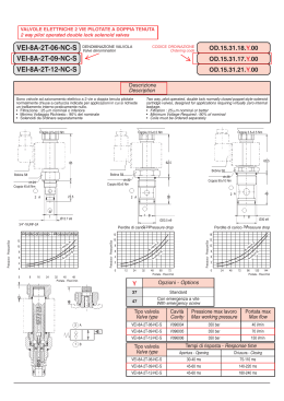
S 180
anagement
ce
di m
rti
01
40
IS O 9
0
01
1
O
a
m
ato
fic
Sis
te
SA
1
H
0
RIDUTTORI
STABILIZZATORI DI PRESSIONE
- IS O
CARATTERISTICHE TECNICHE
1"
3/4"
X
1
0.8
0.5
0.4
0.3
0.2
5
0.2
10 15
0.5
1
30 50
2
3 4 5
500
10 20 30 40 50
Y
l/min
3
m /h
Portata
Flow rate
Caduta di pressione in bar
Loss of pressure bar
1.5
1/2"
Pressione massima di esercizio..............................................40 bar
Pressione di taratura................................................................3 bar
Temperatura max....................................................................85 °C
Campo di regolazione............................................................1-6 bar
Portata..................................................vedi tabella perdite di carico
Generalità
Il riduttore di pressione Rubinetterie Bresciane, è un prodotto utilizzabile per ottenere una pressione a valle idonea a
salvaguardare la rete utente, indipendentemente dalla pressionedi rete. Il riduttore viene consegnato tarato a banco 3 bar.
Installazione
L’installazione deve avvenire nel rispetto dei regolamenti locali, delle direttive generali e delle istruzioni allegate al prodotto.
Il montaggio è possibile in ogni posizione, curando l’accessibilità ed il riparo dal gelo.
Si dovranno predisporre valvole di intercettazione a monte e a valle del riduttore.
- Si consiglia di pulire accuratamente la tubazione prima di installare il riduttore.
- Accertarsi che la freccia, stampata sul corpo, sia in direzione del flusso.
- Accertarsi che gli spazi siano sufficienti per agevolare le manutenzioni.
- Durante il montaggio evitare eccessi di serraggio.
Tarare la pressione a valle
Per modificare la pressione di taratura, dopo aver installato un manometro in posizione A, agire
come segue:
- per aumentare la pressione, chiudere le utenze a valle e agire sulla manopola B, finché non apparirà sul manometro il valore
desiderato
- per diminuire la pressione, chiudere il rubinetto di intercettazione a monte, depressurizzare il riduttore (aprendo ad esempio
un’utenza a valle) ruotare la manopola al valore desiderato evidenziato sul manometro e riaprire lentamente il rubinetto di
intercettazione.
Manutenzione
È da effettuare periodicamente (dipende dalle condizioni di utilizzo), procedere come segue:
1. chiudere le valvole di arresto a monte e a valle
2. svitare il tappo del portamanometro
3. collegare un manometro campione
4. aprire lentamente il rubinetto a monte
5. controllare che la pressione rimanga stabile.
In caso di anomalia (la pressione sale lentamente) chiudere il rubinetto a monte e individuare le possibili cause:
- Elastomero otturatore rovinato
- Guarnizione di tenuta otturatore abrasa
- Membrana fessurata
N.B. La manutenzione straordinaria è opportuno che venga eseguita da personale qualificato.
Foglio istruzioni 90004000010
S 180
anagement
ce
di m
rti
01
40
IS O 9
0
01
1
O
a
m
ato
fic
Sis
te
SA
1
H
0
PRESSURE REDUCING AND
REGULATING VALVES
- IS O
TECHNICAL FEATURES
1"
3/4"
X
1
0.8
0.5
0.4
0.3
0.2
5
0.2
10 15
0.5
1
30 50
2
3 4 5
500
10 20 30 40 50
Y
l/min
3
m /h
Portata
Flow rate
Caduta di pressione in bar
Loss of pressure bar
1.5
1/2"
Maximum pressure.................................................................40 bar
Setting pressure.......................................................................3 bar
Maximum temperature............................................................85 °C
Pressure range.....................................................................1-6 bar
Flow rate............................................................see drop loss chart
Description
The pressure reducing valve of Rubinetterie Bresciane is a product used to obtain a downstream pressure suitable for the
protection of final user piping, independently from the piping network pressure.
The reducer has been tested at 3 bar.
Mounting
Installation must be done respecting local regulations, general directives and according these instructions for use. Place of
installation must be easily accessible and protected from intense cold.
Intercepting valves must be mounted before and after the pressure reducing valve.
- It is suggested to clean pipes before mounting the reducer.
- Make sure that the arrow casted on the body shows the same direction of flow.
- Make sure that there is enough room to successfully operate further maintenance.
- During mounting, avoid excesses in tightening.
Set downstream pressure
To modify setting pressure, after having mounted a pressure gauge in position A, please follow instructions here below:
- To increase pressure, close downstream piping and turn handle B until on the gauge the desired rate appears.
- To decrease pressure close upstream valve, depressurise the reducer (opening forexample an upstream piping network ),
turn the hand grip until the value on the gauge meets the desired level. Then open slowly the downstream valve.
Maintenence
Maintenance has to be done in consequence to the use conditions (at least once a year)
Please follow the instructions here below:
1. close up and downstream valves
2. unscrew the gauge tap
3. connect a pressure gauge
4. open slowly the upstream valve
5. assure that pressure is stable and that it corresponds to the one in the pressure gauge.
In case of technical faults (the pressure increases very slowly), close the upstream valve and check possible causes:
- Damaged shutter elastomer
- Abrased shutter seal
- Broken membrane
Data sheet 90004000010
Scarica