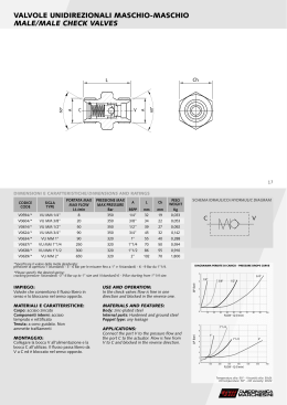
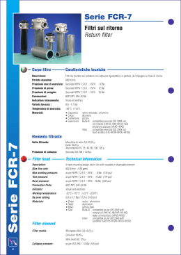
Serie FR-8
Filtri sul ritorno
Return filter
Corpo filtro
Caratteristiche tecniche
Descrizione:
Portata massima:
Pressione max di esercizio:
Pressione di prova:
Pressione di scoppio:
Connessioni:
Indicatore intasamento:
Temperatura di esercizio:
Materiali:
Filtri da montare sul serbatoio con cartuccia rigenerabile o a perdere, da impiegare su linee di ritorno.
150 lt/min
Secondo NFPA T 2.6.1. - 1974 : 8 Bar
Secondo NFPA T 2.6.1. - 1974 : 12 Bar
Secondo NFPA T 2.6.1. - 1974 : 16 Bar
BSP, NPT, SAE J514b
Visivo ed elettrico
-30°C +110°C
• coperchio:
nylon rinforzato
• corpo:
alluminio
• contenitore: nylon rinforzato - acciaio
• guarnizioni: Buna-N compatibile secondo ISO 2943 con
oli minerali (HH-HL-HM-HR-HV-HG)
emulsioni acquose (HFAE-HFAS)
Viton
compatibile secondo ISO 2943 con
fluidi sintetici (HS-HFDR-HFDU-HFDS)
Elemento filtrante
Serie FR-8
Setto filtrante:
Pressione di collasso:
Valvola by-pass :
Microfibra di vetro 3,6,10,25 µ
Carta 10,25 µ
Tela metallica 60,125 µ
Secondo ISO 2941: 10 Bar
1,7 Bar
Filter head
Technical Information
Description:
Max flow rate:
Max working pressure:
Test pressure:
Burst pressure:
Port connections:
Indicator:
Working temperature:
Materials:
IIn tank mounting design return line with reusable or not reusable element.
150 lt/min (40 gpm)
as per NFPA T 2.6.1 - 1974: 8 Bar (116 psi)
as per NFPA T 2.6.1 - 1974: 12 Bar (174 psi)
as per NFPA T 2.6.1 - 1974: 16 Bar (232 psi)
BSP, NPT, SAE J514b
Visual and electrical.
-30°C +110°C (-22°F +230°F)
• cover:
nylon
• head:
alluminium
• housing:
nylon - carbon steel
Buna-N compatible as per ISO 2943 with
• Seal:
mineral oil (HH-HL-HM-HR-HV-HG)
water oil emulsions (HFAE-HFAS)
compatible as per ISO 2943 with
Viton
synthetic fluid (HS-HFDR-HFDU-HFDS)
Filter element
Filter media:
Microglass fiber 3,6,10,25 µ
Cellulose 10,25 µ
Wire mesh 60, 125 µ
Collapse pressure:
By-pass:
38
as per ISO 2941: 10 Bar (145 psi)
return line 1,7 Bar (24.6 psi)
Informazioni dimensionali Overall dimensions
H
F
9
I
H
A
G
H
E
2 FORI M8
THREAD HOLE
D
C
B
L
1
POSIZONE INGRESSO SECONDARIO (Q)
SECOND PORT OPTION (Q)
2
POSIZIONE INDICATORE
INDICATOR PORT
3
FILTRO SFIATO
AIR BREATHER
M
2
Q
1 2
DESTRA / RIGHT
N
3
SINISTRA / RIGHT
1
1 2
8,5
P
1) Grandezza nominale Nominal size
Codice - Code
A
B
C
D
E
F
G
H
I
L
M
N
O
P
Q
Cart. ricambio - Replay element
67
62
24
22
79
81
84
25
55
54
89 ± 1
68
73
---
R-1-10
67
62
24
22 148
81
84
25
55
54
89 ± 1
68
73
---
R-1-11
86 80,5 27,5 27 103 107 110 40
67
68
115 ± 1
87
94
3/8” - 1/2" - 3/4" BSP
FR-8-10
3/8” - 1/2" - 3/4" NPT
9/16”-18 UN - SAE J514b
3/4”-16 UN - SAE J514b
FR-8-11
1 1/16”-12 UN-SAE J514b
1/2" - 3/4"- 1" - 1 1/4" BSP
3/8” - 1/2" BSP
FR-8-20
1/2" - 3/4"- 1"- 1 1/4" NPT
R-1-20
3/8” - 1/2" NPT
3/4”-16 UN - SAE J514b
1 1/16”-12 UN-SAE J514b
9/16”-18 UN - SAE J514b
FR-8-22
1 5/16”-12 UN-SAE J514b
86 80,5 27,5 27 148 107 110 40
67
68
115 ± 1
87
94
R-1-22
1 5/8”-12 UN-SAE J514b
3/4”-16 UN - SAE J514b
3/4" - 1"- 1 1/4" BSP
3/8” - 1/2" BSP
3/4" - 1"- 1 1/4" NPT
3/8” - 1/2" NPT
FR-8-30
1 1/16”-12 UN-SAE J514b
86 80,5 40
29 229 107 110 40
67
68
115 ± 1
87
94
R-1-30
1 5/16”-12 UN-SAE J514b
9/16”-18 UN - SAE J514b
1 5/8”-12 UN-SAE J514b
3/4”-16 UN - SAE J514b
39
2) Grado di filtrazione Filtration ratings
Materiale - Media
Efficienza - Efficiency
senza cartuccia / no element
------
G03
microfibra inorganica / microglass fiber
ß 3 ≥ 1000
G06
microfibra inorganica / microglass fiber
ß 6 ≥ 1000
G10
microfibra inorganica / microglass fiber
ß 10 ≥ 1000
G25
microfibra inorganica / microglass fiber
ß 25 ≥ 1000
C10
carta trattata / resin impregnated cellulose
ß 10 ≥ 2
C25
carta trattata / resin impregnated cellulose
ß 25 ≥ 2
T60
tela metallica / wire mesh
------
T125
tela metallica / wire mesh
------
Codice - Code
0
3) Guarnizioni Seals
Codice - Code Tipo - Type
---
NBR
V
Viton
4) Connessioni Connection port
Codice - Code
Connessione - Connection
B2
3/8” BSP
B3
1/2” BSP
B4
3/4” BSP
B5
1” BSP
B6
1 1/4” BSP
N2
3/8” NPT
N3
1/2" NPT
N4
3/4” NPT
N5
1” NPT
N6
R2
1 1/4” NPT
9/16” - 18 UNF-2B SAE J514b
R3
3/4” - 16 UNF-2B SAE J514b
R4
1 1/16” - 12 UNF-2B SAE J514b
R5
1 5/16” - 12 UNF-2B SAE J514b
R6
1 5/8” - 12 UNF-2B SAE J514b
5) Posizione ingressi secondari Second port position
Codice - Code Posizione - Position
40
0
senza - wihout
D
destra - right
S
sinistra - left
6) Ingressi secondari Second portconnection
Codice - Code
Connessione - Connection
B2
3/8” BSP
B3
1/2” BSP
N2
3/8” NPT
N3
1/2" NPT
R2
9/16” - 18 UNF-2B SAE J514b
R3
3/4” - 16 UNF-2B SAE J514b
7) Sfiato aria Air breather
Codice - Code
0
Micronaggio - Micron rating
senza / without
sfiato 10µ
10
10 µ air breather
sfiato 40µ
40
40 µ air breather
8) Posizione indicatore Indicator position
Codice - Code Posizione - Position
O
senza / without
C
coperchio / cover
D
destra / right
S
sinistra / left
9) Indicatori Indicator
Codice - Code
0
Tipo indicatore - Indicator type
senza / without
manometro scala 0 ÷ 10 Bar
R1
pressure gauge indicator scale 0 ÷ 10 Bar
pressostato n.a. taratura 1,3 Bar
R2
pressure switch 1,3 Bar setted O.C.
pressostato n.c. taratura 1,3 Bar
R3
pressure switch 1,3 Bar setted C.C.
Codici per l’ordinazione Ordering information
Filtro completo
Filter assembly
Cartuccia
Filter elements
FR-8
R-1
20
C10
1*
2*
B
20
C10
1*
2*
V
B3
D
B2
40
C
R1
3*
4*
5*
6*
7*
8*
9*
B
V
3*
41
Curve di portata Pressure drop charts
Le curve (secondo ISO 3968 classe B) sono ottenute con olio minerale avente viscosità di 30 cSt e densità di 0,86 Kg/dm3.
Per viscosità e densità diverse i dati variano, in prima approssimazione proporzionalmente.
Il numero relativo alla curva di portata è riferito all’attacco del filtro; es.: 2 indica attacco B2 o N2.
Pressure drop charts as per ISO 3968 class B. 30 Cst viscosity mineral oil
The numbers indicate connection of the filters: i.e. 2 means B2 or N2 connections.
Portata (l/min)
Dp (PSI)
Dp (bar)
FR-8-20 / 22
Flow rate (GPM)
Dp (PSI)
Dp (bar)
FR-8-10 / 11
Flow rate (GPM)
Portata (l/min)
Dp (PSI)
Dp (bar)
FR-8-30
Flow rate (GPM)
Portata (l/min)
Portata (l/min)
42
Dp (PSI)
Dp (bar)
Flow rate (GPM)
Dp (PSI)
Dp (bar)
R-1-10
Flow rate (GPM)
Portata (l/min)
Dp (PSI)
Dp (bar)
Dp (PSI)
Dp (bar)
Flow rate (GPM)
Flow rate (GPM)
Flow rate (GPM)
Dp (PSI)
Dp (PSI)
Dp (bar)
Portata (l/min)
Dp (bar)
Portata (l/min)
Flow rate (GPM)
Flow rate (GPM)
Dp (PSI)
Dp (PSI)
Dp (bar)
Portata (l/min)
Dp (bar)
Portata (l/min)
Portata (l/min)
Flow rate (GPM)
Flow rate (GPM)
Dp (PSI)
Dp (PSI)
Portata (l/min)
Dp (bar)
Portata (l/min)
Dp (bar)
R-1-30
R-1-22
R-1-20
R-1-11
Flow rate (GPM)
Portata (l/min)
43
Scarica