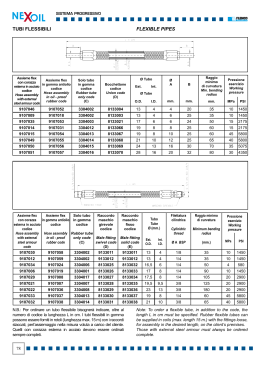
Edition 2013.01
Sistema di Trattenimento per Tubi Flessibili in Pressione
Retention System for Pressure Hoses
▼SICUREZZA TESTATA PER GLI IMPIANTI OLEODINAMICI
▼FOR SAFER PLANTS
INTERNATIONAL
PATENT PENDING
ISO 4413 TRASMISSIONI IDRAULICHE,
REGOLE GENERALI RELATIVE AI SISTEMI:
“Se la rottura di una tubazione flessibile costituisce
rischio, questa deve essere trattenuta o schermata”.
ISO 4413 HYDRAULIC FLUID POWER,
GENERAL RULES RELATING TO SYSTEM:
“Should the rapture of a hose assembly represent
a whiplash hazard, the latter shall be restrained or
shielded”.
P.02
Espositori disponibili su richiesta per i
nostri rivenditori.
Display racks available upon
request for our dealers.
OP Srl si riserva il diritto di modificare in qualsiasi momento e senza necessità di preavviso le informazioni tecniche contentute nel presente catalogo.
OP Srl reserves the right to modify technical information contained in this catalogue at any time and without prior notice.
Garanzia di sicurezza
Safety guarantee
La forza sprigionata da un tubo flessibile in pressione, in caso di sfilamento dal raccordo, potrebbe risultare molto pericolosa per cose o
persone nelle vicinanze.
Il sistema di trattenimento Stopflex è stato ideato per arrestare la corsa del tubo sfilato ed evitare che la forza sprigionata al suo interno
possa innescare un temibile “effetto frusta”.
Grazie al sistema Stopflex, infatti, il tubo flessibile viene ancorato tramite una fune all’impianto garantendo così la piena tutela degli operatori e la salvaguardia dei componenti.
The energy contained within a pressure hose, in case of disconnection
from the fitting, can be very dangerous to anyone or anything in its
vicinity.
The Stopflex retention system was designed to arrest the trajectory of
the flexible hose, thus avoiding that the energy contained inside may
trigger a frightening “whip effect”.
As a matter of fact, thanks to the Stopflex system, the hose is secured
to the plant by means of a cable protecting both the operators and
components.
Flessibilità di utilizzo
Use flexibility
I componenti Stopflex possono essere applicati a tutti i tipi di tubo
flessibile. La fascetta, munita di guarnizione, rimane perfettamente
ancorata al tubo pur consentendo alla condotta di polmonare in base
alla pressione di esercizio. L’ancoraggio può essere applicato a nippli,
a flange SAE o a diversi componenti dell’impianto.
Stopflex components can be applied to all kinds of flexible hoses.
A band, equipped with a rubber gasket, remains perfectly secured,
simultaneously allowing the hose to swell according to the working
pressure. The retaining components can be secured to nipples, to
SAE flanges or other system components.
www.stopflex.it
Protezione collaudata
Tested protection
Il sistema Stopflex, previo corretto montaggio, è stato realizzato e collaudato per garantire il trattenimento del tubo fino alla pressione massima indicata nel presente catalogo facendo riferimento alle seguenti
norme che regolano la costruzione dei tubi flessibili oleodinamici:
The Stopflex system, upon correct mounting, was manufactured and
tested to ensure the retention of the hose up to the maximum pressure
indicated in this catalogue in compliance with the following standards
regulating the manufacture of hydraulic flexible hoses:
EN 853
EN 856
EN 853
EN 856
EN 854
EN 857
EN 855
SAE J517
EN 854
EN 857
EN 855
SAE J517
_______________________________________________________
_______________________________________________________
N.B.
N.B.
Esistono sul mercato tubazioni flessibili oleodinamiche che potrebbero
In the market there are hydraulic flexible hoses capable of exceeding
superare le pressioni indicate nel presente catalogo ed in presenza
the pressures indicated in this catalogue. In case you encounter such
delle quali vi invitiamo a contattare il nostro ufficio tecnico per ulteriori
hoses, please contact our technical department for further ascertain-
verifiche dell’applicazione.
ment regarding application thereof.
E-mail: [email protected]
E-mail: [email protected]
P.03
▼PRINCIPI DI FUNZIONAMENTO
▼BASICS OF USE
1a FASE: SFILAMENTO
2a FASE: RILASCIO / SFOGO DELLA PRESSIONE
Il sistema Stopflex non entra in funzione durante la fase di sfilamento
In questa fase l’olio in pressione fuoriesce dal tubo flessibile che inizia
del tubo flessibile ma, se applicato correttamente, fa in modo che il
a sprigionare tutta la forza che tratteneva al suo interno acquistando
tubo si sganci completamente dalla bussola che lo trattiene.
notevole velocità e innescando un temibile “effetto frusta”, molto peri-
Durante questa fase il tubo flessibile acquista velocità e potenza a
coloso per cose o persone nelle sue vicinanze.
causa dell’aumento della pressione dell’olio in esso contenuto.
STEP 1: DISENGAGEMENT
STEP 2: RELEASE / VENTING OF PRESSURE
During this step, the pressurised oil exits from the flexible hose.
The Stopflex system does not operate during the step of disengaging
The hose begins to release the energy contained therein, and gains
the flexible hose, but, if applied correctly, it ensures that the hose is
considerable velocity, triggering a hazardous “whip effect” which is
fully disengaged from the ferrule that restrains it. During this step, the
very dangerous to anyone or anything in its vicinity.
flexible hose gains velocity and power due to the pressure increase of
the oil contained therein.
1
STEP 1
2
STEP 2
►PRINCIPI DI MONTAGGIO
►ASSEMBLY BASICS
P.04
La procedura di montaggio dell’applicazione è fondamentale per ga-
The assembly procedure of the application is fundamental to ensure
rantire il corretto funzionamento del sistema Stopflex.
the correct operation of the Stopflex system.
Infatti, se non vengono eseguite correttamente le istruzioni di montag-
As a matter of fact, failure to carefully follow the assembly in-
gio allegate a tutte le confezioni, esiste il fondato rischio che il sistema
structions provided with all packagings, may actually jeopardise the
non funzioni.
operation of the system.
Dopo numerosi test su banchi di collaudo è stata trovata la combina-
After numerous tests on the test benches, we found the ideal com-
zione ottimale fra materiali e procedimento di montaggio in modo da
bination of materials and assembly procedure to ensure the utmost
garantire la piena efficienza del sistema.
efficiency in the system.
3a FASE: TRATTENIMENTO
STEP 3: RESTRAINT
Sfilato il tubo e sfogata la pressione, il tubo flessibile deve quindi es-
Once the hose has been disengaged and the pressure released, the
sere trattenuto, ed è in questa fase che entra in funzione il sistema
flexible hose can be restrained. This is where the Stopflex system gets
Stopflex: la fune d’acciaio si tende e si deforma mentre la piastrina
into operation: the stainless steel cable is tensioned and deformed
incide la gomma del tubo impedendo il distacco della fascetta, salda-
while the plate cuts into the rubber of the hose, preventing the clamp,
mente ancorata al tubo. Fascetta e piastrina cominciano a loro volta
firmly attached to the hose, from disengaging. The hose clamp and
a deformarsi elasticamente assorbendo la forza scatenata dalla corsa
plate start to deform in turn, elastically absorbing the force released
del tubo flessibile.
from the travel of the flexible hose. This is a critical step which occurs
Si tratta di una fase molto critica che si verifica in poche frazioni di
within just a few seconds in which the materials and the components
secondo durante le quali i materiali e le forme del sistema, preceden-
of the system, previously sized and tested, stop the dangerous travel
temente dimensionati e testati, arrestano la pericolosa corsa del tubo
of the flexible hose.
flessibile.
BASICS
OF USE
3
STEP 3
• Condizioni ambientali particolari quali le luci ultraviolette, l’ozono, l’ac-
• Given environmental conditions such as ultraviolet light, ozone, salty water,
qua salata, gli agenti chimici (solventi, carburanti, oli, grassi, composti
chemical agents (solvents, fuels, oils, greases, volatile chemical compoun-
chimici volatili, acidi, disinfettanti ed altri elementi aggressivi) possono
ds, acids, disinfectants and other aggressive elements) can cause early de-
provocare una precoce degradazione della guarnizione della fascetta;
terioration of the band seal;
• Provvedere alla sostituzione della guarnizione ogni 4 anni se la fa-
• The seal must be replaced every 4 years if the band is not assem-
scetta non viene assemblata;
bled;
• Provvedere alla sostituzione della guarnizione ogni 2 anni se la fa-
• The seal must be replaced every 2 years if the band is assembled;
scetta viene assemblata;
• The STOPFLEX system must never be re-used in case of hose rupture,
• Il sistema STOPFLEX non deve mai essere riutilizzato in caso di
slip-off or replacement of the hose, as this will jeopardise the initial safety
scoppio, sfilamento o sostituzione della tubazione, in quanto verrebbe-
features of the system.
ro a mancare le caratteristiche di sicurezza originali.
Should the system be re-used, the assembler will be held entirely liable
In caso di riutilizzo la responsabilità ricade completamente sull’assem-
therefor.
blatore.
P.05
▼ELEMENTI DI TENUTA PER NIPPLI
▼NIPPLE RETENTION SYSTEM
ø inches
SP./TH
mm
inches
xinches
STOPFUDIN145
14,5
0,571
2
0,079
300
11,811
10
450
6525
STOPFUDIN17
17
0,669
2
0,079
300
11,811
10
445
6453
STOPFUDIN185
18,5
0,728
2
0,079
300
11,811
10
420
6090
STOPFUDIN205
20,5
0,807
2
0,079
300
11,811
10
420
6090
STOPFUDIN225
22,5
0,886
2
0,079
300
11,811
10
420
6090
STOPFUDIN245
24,5
0,965
2
0,079
300
11,811
10
420
6090
STOPFUDIN265
26,5
1,043
2
0,079
300
11,811
10
420
6090
STOPFUDIN305
30,5
1,201
2,5
0,098
300
11,811
10
420
6090
STOPFUDIN34
34
1,339
2,5
0,098
450
17,717
10
420
6090
STOPFUDIN365
36,5
1,437
2,5
0,098
450
17,717
10
420
6090
STOPFUDIN425
42,5
1,673
2,5
0,098
450
17,717
10
420
6090
STOPFUDIN455
45,5
1,791
2,5
0,098
450
17,717
10
420
6090
STOPFUDIN49
49
1,929
2,5
0,098
450
17,717
10
420
6090
STOPFUDIN525
52,5
2,067
2,5
0,098
450
17,717
10
385
5583
STOPFUDIN60
60
2,362
2,5
0,098
450
17,717
10
350
5075
CODICE
CODE
SP/TH
ø
L.
CODICE
CODE
SP/TH
1
ø
1
ø mm
ø mm
ø inches
1
Nr. Pezzi P. Max di lav.
L. mmx=y
Max operating P.
No. of PCS
bar - psi
SP./TH
L. mm
mm
inches
inches
y
1
Nr. Pezzi P. Max di lav.
Max operating P..
No. of PCS
bar - psi
STOPFUSAE085
8,5
0,335
4
0,157
300
11,811
10
415
6018
STOPFUSAE2105*
10,5
0,413
4
0,157
300
11,811
10
420
6090
STOPFUSAE105
10,5
0,413
4
0,157
450
17,717
10
420
6090
STOPFUSAE125
12,5
0,492
4
0,157
450
17,717
10
420
6090
STOPFUSAE145
14,5
0,571
4
0,157
450
17,717
10
420
6090
STOPFUSAE165
16,5
0,650
4
0,157
450
17,717
10
420
6090
STOPFUSAE205
20,5
0,807
4
0,157
450
17,717
10
350
5075
STOPFUSAE25
25
0,984
8
0,315
550
21,654
10
350
5075
STOPFUSAE32
32
1,260
8
0,315
550
21,654
10
210
3045
Piastrina incisione
Cutting Plate
O+p ITALY
Piastrina incisione
Cutting Plate
O+p ITALY
Intesa come pressione MAX di lavoro del sistema di trattenimento Stopflex.
Intended as the MAX operating pressure of the Stopflex retention system.
* Applicazioni con flange SAE 3000 per tubi da 3/4”.
* Applications with SAE 3000 flanges for 3/4” hoses.
L.
▲ELEMENTI DI TENUTA PER FLANGE SAE 3000 E SAE 6000
▲RETENTION SYSTEM FOR SAE 3000 AND SAE 6000 FLANGES
P.06
ELEMENTI DI TENUTA PER IMPIEGHI VARI ▼
RETENTION SYSTEM FOR VARIOUS USES ▼
CODICE
CODE
STOPFUVARIE
ø inches
SP./TH
mm
L. mm
13
0,512
4
0,157
450
17,717
ø mm
inches
inches
1
Nr. Pezzi P. Max di lav.
Max operating P.
No. of PCS
bar - psi
10
Piastrina incisione
Cutting Plate
420
6090
O+p ITALY
1
1
Intesa come pressione MAX di lavoro del sistema di trattenimento Stopflex.
Intended as the MAX operating pressure of the Stopflex retention system.
CODICE
CODE
ø MIN
ø MAX
mm
inches
Nr. Pezzi
No. of PCS
0,433
11,5
0,453
10
0,472
12,5
0,492
10
13
0,512
13,5
0,531
10
STOPFA1415
14
0,551
15
0,591
10
STOPFA1617
16
0,630
17
0,669
10
STOPFA1718
17
0,669
18
0,709
10
STOPFA1819
18
0,709
19
0,748
10
STOPFA2021
20
0,787
21
0,827
10
STOPFA2122
21
0,827
22
0,866
10
STOPFA2223
22
0,866
23
0,906
10
STOPFA2425
24
0,945
25
0,984
10
STOPFA2526
25
0,984
26
1,024
10
STOPFA2627
26
1,024
27
1,063
10
STOPFA2728
27
1,063
28
1,102
10
STOPFA2829
28
1,102
29
1,142
10
STOPFA3031
30
1,181
31
1,220
10
STOPFA3233
32
1,260
33
1,299
10
STOPFA3435
34
1,339
35
1,378
10
STOPFA3637
36
1,417
37
1,457
10
STOPFA3839
38
1,496
39
1,535
10
STOPFA3940
39
1,535
40
1,575
10
STOPFA4041
40
1,575
41
1,614
10
STOPFA4243
42
1,654
43
1,693
10
STOPFA4344
43
1,693
44
1,732
10
STOPFA4445
44
1,732
45
1,772
10
STOPFA4547
45
1,772
47
1,850
10
STOPFA4850
48
1,890
50
1,969
10
STOPFA5153
51
2,008
53
2,087
10
STOPFA5354
53
2,087
54
2,126
10
STOPFA5456
54
2,126
56
2,205
10
STOPFA5759
57
2,244
59
2,323
10
STOPFA6062
60
2,362
62
2,441
10
STOPFA6365
63
2,480
65
2,559
10
STOPFA6668
66
2,598
68
2,677
10
STOPFA6971
69
2,717
71
2,795
10
STOPFA7274
72
2,835
74
2,913
10
STOPFA7577
75
2,953
77
3,031
10
STOPFA7880
78
3,071
80
3,150
10
STOPFA8183
81
3,189
83
3,268
10
STOPFA8486
84
3,307
86
3,386
10
STOPFA8789
87
3,425
89
3,504
10
STOPFA9092
90
3,543
92
3,622
10
STOPFA9395
93
3,661
95
3,740
10
mm
inches
STOPFA11115
11
STOPFA12125
12
STOPFA13135
SP/TH
ø
L.
ø MIN
ø MAX
11-11.5
ITALY
0000
NB: I diametri riportati in tabella sono indicativi, è possibile che al serraggio delle fascette questi varino leggermente.
NB: The diameters indicated in the table shall be deemed indicative. They could slightly vary upon tightening the band.
FASCETTE STOPFLEX PER TUBO FLESSIBILE ▲
STOPFLEX HOSE BANDS ▲
P.07
© AP&P srl - www.ap-p.it
®
E-COMMERCE WEBSITE:
www.stopflex.it
OP Srl
Via del Serpente, 97 - 25131 Brescia - Italy
Phone +39.030.35.80.401 - Fax +39.030.35.80.838
e-mail: [email protected] - www.op-srl.it
Scarica