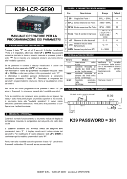
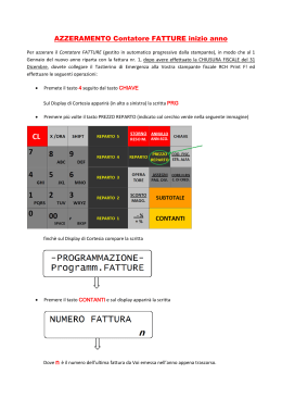
9 - Led ALARM : Indica lo stato di allarme on (acceso), off (spento) o
tacitato (lampeggiante)
10 - Led Stand-By: Quando lo strumento viene posto nella modalità
stand-by resta l’unico led acceso.
Z31- / Z31A / Z31V
Z31S / Z31SA / Z31SV
CONTROLLORE / REGOLATORE /
VISUALIZZATORE ELETTRONICO DI
TEMPERATURA
ELECTRONIC TEMPERATURE
CONTROLLER / THERMOMETER
SHORT OPERATING INSTRUCTIONS
ITA / ENG - Vr. 02 - 03/12 - ISTR-FZ31-IE02
ASCON TECNOLOGIC S.r.l.
VIA INDIPENDENZA 56
27029 VIGEVANO (PV) ITALY
TEL.: +39 0381 69871
FAX: +39 0381 698730
http:\\www.ascontecnologic.com
e-mail: [email protected]
PREMESSA / FOREWORD
Nel presente manuale sono contenute le informazioni
necessarie ad una corretta installazione e le istruzioni per
l'utilizzo e la manutenzione del prodotto, si raccomanda
pertanto di leggerlo attentamente e di conservarlo. La
presente pubblicazione è di esclusiva proprietà della
ASCON TECNOLOGIC la quale pone il divieto assoluto di
riproduzione e divulgazione, anche parziale, se non espressamente
autorizzata. La ASCON TECNOLOGIC si riserva di apportare modifiche
estetiche e funzionali in qualsiasi momento e senza alcun preavviso.
Qualora un guasto o un malfunzionamento dell'apparecchio possa
creare situazioni pericolose o dannose per persone, cose o animali si
ricorda che l'impianto deve essere predisposto con dispositivi aggiuntivi atti a garantire la sicurezza. La ASCON TECNOLOGIC ed i suoi
legali rappresentanti non si ritengono in alcun modo responsabili per
eventuali danni a persone, cose o animali derivanti da manomissioni,
uso improprio, errato o comunque non conforme alle caratteristiche
dello strumento.
Per maggiori informazioni scaricare il manuale d’uso completo dal
sito www.ascontecnologic.com
This manual contains the information necessary for the product to be
installed correctly and also instructions for its maintenance and use; we
therefore recommend that the utmost attention is paid to the following
instructions and to save it. This document is the exclusive property of
ASCON TECNOLOGIC which forbids any reproduction and divulgation ,
even in part, of the document, unless expressly authorized. ASCONT
ECNOLOGIC reserves the right to make any formal or functional
changes at any moment and without any notice. Whenever a failure or
a malfunction of the device may cause dangerous situations for
persons, thing or animals, please remember that the plant has to be
equipped with additional devices which will guarantee safety. ASCON
TECNOLOGIC and its legal representatives do not assume any
responsibility for any damage to people, things or animals deriving from
violation, wrong or improper use or in any case not in compliance with
the instrument’s features.
For more informations download the detailed operating
instructions from www.ascontecnologic.com
DESCRIZIONE STRUMENTO
Il modello Z31 è un termoregolatore elettronico digitale a microprocessore utilizzabile tipicamente per applicazioni di refrigerazione dotato di
controllo di temperatura con regolazione ON/OFF e controllo di sbrinamento a intervalli di tempo mediante fermata compressore.
Lo strumento prevede un uscita a relè e un ingresso per sonde di
temperatura PTC o NTC inoltre può essere equipaggiato da un buzzer
interno per la segnalazione acustica degli allarmi.
Il modello Z31A è un termoregolatore non dotato del controllo di sbrinamento mentre il modello Z31V è un visualizzatore di temperatura.
I modelli Z31S, Z31SA e Z31SV si differenziano dai modelli standard
per l’estetica e la tastiera a sfioramento di tipo capacitivo denominata
“S-touch”.
8
4
6
3
9
2
7
1
10
5
1 - Tasto P : Premuto e rilasciato rapidamente consente l’accesso
all'impostazione del Set point.
Premuto per 5 sec. consente l’accesso alla modalità di programmazione parametri.
In modalità di programmazione viene utilizzato per accedere all’editazione dei parametri e per la conferma dei valori.
Sempre in modalità di programmazione può essere utilizzato insieme al
tasto UP per modificare il livello di programmazione dei parametri.
Premuto insieme al tasto UP per 5 sec. quando la tastiera è bloccata
consente lo sblocco della tastiera.
2 - Tasto DOWN: Nelle modalità di programmazione viene utilizzato
per il decremento dei valori da impostare e per la selezione dei
parametri.
3 - Tasto UP/ DEFROST: Nella normale modalità di funzionamento
premuto per 5 sec. consente di attivare/disattivare un ciclo di sbrinamento manuale.
Nelle modalità di programmazione viene utilizzato per l'incremento dei
valori da impostare e per la selezione dei parametri.
Sempre in modalità di programmazione può inoltre essere utilizzato
insieme al tasto P per modificare il livello di programmazione dei
parametri.
Premuto insieme al tasto P per 5 sec. quando la tastiera è bloccata
consente lo sblocco della tastiera.
4 - Tasto U : Premuto e rilasciato rapidamente consente di visualizzare
le variabili dello strumento (temperature misurate, etc.).
Nella modalità di programmazione viene utilizzato per uscire dalla
modalità e tornare al normale funzionamento.
Se programmato tramite il par. “t.UF” consente, premuto per 1 sec.
nella normale modalità di funzionamento, l’accensione/spegnimento
(Stand-by).
5 - Led SET : Nella normale modalità di funzionamento si accende
quando un tasto è premuto per segnalare l’avvenuta pressione del
medesimo.
Nella modalità di programmazione viene utilizzato per indicare il livello
di programmazione dei parametri.
6 - Led OUT - COOL : Indica lo stato dell'uscita di regolazione
(compressore o dispositivo di controllo della temperatura) quando
l’azione operante è quella di raffreddamento; uscita attivata (acceso),
disattivata (spento), inibita (lampeggiante).
7 - Led OUT - HEAT : Indica lo stato dell'uscita di regolazione
(compressore o dispositivo di controllo della temperatura) quando
l’azione operante è quella di riscaldamento; uscita attivata (acceso),
disattivata (spento), inibita (lampeggiante).
8 - Led DEF : Indica lo stato dello sbrinamento in corso.
1
PROGRAMMAZIONE
IMPOSTAZIONE RAPIDA DEL SET POINT (non presente nel modello
V)- Premere il tasto P quindi rilasciarlo e il display visualizzerà “SP”
alternato al valore impostato.
Per modificarlo agire sui tasti UP per incrementare il valore o DOWN
per decrementarlo. Una volta impostato il valore desiderato premendo il
tasto P si esce dalla modalità rapida di impostazione del Set Point
oppure attendere l’uscita automatica non agendo su alcun tasto per
circa 10 secondi, trascorsi i quali il display tornerà al normale modo di
funzionamento.
PROGRAMMAZIONE STANDARD DEI PARAMETRI - Per avere
accesso ai parametri di funzionamento dello strumento quando la
protezione dei parametri non è attiva occorre premere il tasto P e
mantenerlo premuto per circa 5 secondi, trascorsi i quali il display
visualizzerà il codice che identifica il primo parametro e con i tasti UP e
DOWN sarà possibile selezionare il parametro che si intende editare.
Una volta selezionato il parametro desiderato premere il tasto P e verrà
visualizzato il codice del parametro e la sua impostazione che potrà
essere modificata con i tasti UP o DOWN. Impostato il valore desiderato premere nuovamente il tasto P: il nuovo valore verrà memorizzato
e il display mostrerà nuovamente solo la sigla del parametro selezionato. Agendo sui tasti UP o DOWN è quindi possibile selezionare un altro
parametro e modificarlo come descritto. Per uscire dal modo di
programmazione non agire su alcun tasto per circa 30 secondi, oppure
premere il tasto U per circa 2 sec. sino ad uscire dalla modalità di
programmazione.
PROTEZIONE DEI PARAMETRI MEDIANTE PASSWORD - Lo
strumento dispone di una funzione di protezione dei parametri
mediante password personalizzabile attraverso il par. “t.PP”. Qualora
si desideri disporre di questa protezione impostare al parametro “t.PP”
il numero di password desiderato e uscire dalla programmazione
parametri. Quando la protezione è attiva, per poter aver accesso ai
parametri, premere il tasto P e mantenerlo premuto per circa 5 secondi,
trascorsi i quali, il display visualizzerà “r.P” e premendo ancora il tasto
P il display visualizzerà “0” . A questo punto impostare, attraverso i tasti
UP e DOWN, il numero di password programmato e premere il tasto P.
RIPRISTINO DELLA CONFIGURAZIONE PARAMETRI DI DEFAULT Lo strumento consente il reset dei parametri ai valori impostati in
fabbrica come default. Per ripristinare ai valori di default i parametri è
sufficiente impostare alla richiesta di “r.P” la password -48. Pertanto,
qualora si desideri realizzare tale reset occorre abilitare la Password
mediante il parametro “t.PP” in modo che venga richiesta l’impostazione di “r.P” e quindi impostare “-48” anzichè la password di accesso
programmata. Una volta confermata la password con il tasto P il display
mostra per circa 2 sec. “- - -” quindi lo strumento effettua il reset dello
strumento come all'accensione e ripristina ai valori di default
programmati in fabbrica tutti i parametri.
FUNZIONE BLOCCO TASTI - Sullo strumento è possibile il blocco
totale dei tasti. La funzione di blocco della tastiera è attivabile programmando il parametro “t.Lo” ad un qualsiasi valore diverso da oF .
Pertanto non premendo alcun tasto per il tempo “t.Lo” lo strumento
blocca automaticamente le normali funzioni dei tasti. Premendo un
qualsiasi tasto quando la tastiera è bloccata il display mostra “Ln” per
avvisare del blocco attivo. Per sbloccare la tastiera occorre premere
contemporaneamente i tasti P e UP e mantenerli premuti per 5 sec.,
trascorsi i quali il display mostrerà “LF” e tutte le funzioni dei tasti risulteranno di nuovo operative.
AVVERTENZE PER INSTALLAZIONE ED USO
USO CONSENTITO - Lo strumento è stato concepito come apparecchio di misura e regolazione in conformità con la norma EN60730-1 per
il funzionamento ad altitudini sino a 2000 m. L’utilizzo dello strumento
in applicazioni non espressamente previste dalla norma sopra citata
deve prevedere tutte le adeguate misure di protezione. Lo strumento
NON può essere utilizzato in ambienti con atmosfera pericolosa
(infiammabile od esplosiva) senza una adeguata protezione. Lo
strumento, se utilizzato con sonda Tecnologic NTC 103AT11 (riconoscibile dal codice stampato sulla parte sensibile), risulta conforme alla
norma EN 13485 (“Termometri la misurazione della temperatura
dell’aria e dei prodotti per il trasporto, la conservazione e la
distribuzione di prodotti alimentari refrigerati, congelati, surgelati e
gelati”) con la seguente designazione: [aria, S, A, 2,- 50°C +90°C]. Si
ricorda che tali termometri, quando si trovano in servizio, devono
essere verificati periodicamente a cura dell'utilizzatore finale in
conformità alla norma EN 13486.Si ricorda che l’installatore deve
assicurarsi che le norme relative alla compatibilità elettromagnetica
siano rispettate anche dopo l’installazione dello strumento, eventualmente utilizzando appositi filtri. Qualora un guasto o un malfunzionamento dell'apparecchio possa creare situazioni pericolose o dannose
per persone, cose o animali si ricorda che l'impianto deve essere predisposto con dispositivi elettromeccanici aggiuntivi atti a garantire la
sicurezza.
MONTAGGIO MECCANICO - Lo strumento, in contenitore 78 x 35 mm
, è concepito per il montaggio ad incasso a pannello entro un involucro.
Praticare quindi un foro 71 x 29 mm ed inserirvi lo strumento fissandolo
con le apposite staffe fornite. Si raccomanda di montare l'apposita
guarnizione per ottenere il grado di protezione frontale dichiarato.
Evitare di collocare la parte interna dello strumento in luoghi soggetti
ad alta umidità o sporcizia che possono provocare condensa o introduzione nello strumento di parti o sostanze conduttive. Assicurarsi che lo
strumento abbia una adeguata ventilazione ed evitare l’installazione in
contenitori dove sono collocati dispositivi che possano portare lo
strumento a funzionare al di fuori dai limiti di temperatura dichiarati.
Installare lo strumento il più lontano possibile da fonti che possono
generare disturbi elettromagnetici come motori, teleruttori, relè, elettrovalvole ecc.
COLLEGAMENTI ELETTRICI - Effettuare le connessioni collegando
un solo conduttore per morsetto e seguendo lo schema riportato,
controllando che la tensione di alimentazione sia quella indicata sullo
strumento e che l'assorbimento degli attuatori collegati allo strumento
non sia superiore alla corrente massima consentita. Lo strumento,
essendo
previsto
per
collegamento
permanente
entro
un'apparecchiatura, non è dotato nè di interruttore nè di dispositivi
interni di protezione da sovracorrenti. Si raccomanda pertanto di
prevedere l’installazione di un interruttore/sezionatore di tipo bipolare,
marcato come dispositivo di disconnessione, che interrompa
l’alimentazione dell’apparecchio. Tale interruttore deve essere posto il
più possibile vicino allo strumento e in luogo facilmente accessibile
dall’utilizzatore. Inoltre si raccomanda di proteggere adeguatamente
tutti i circuiti connessi allo strumento con dispositivi (es. fusibili)
adeguati alle correnti circolanti. Si raccomanda di utilizzare cavi con
isolamento appropriato alle tensioni, alle temperature e alle condizioni
di esercizio e di fare in modo che i cavi relativi ai sensori di ingresso
siano tenuti lontani dai cavi di alimentazione e da altri cavi di potenza
al fine di evitare l’induzione di disturbi elettromagnetici. Se alcuni cavi
utilizzati per il cablaggio sono schermati si raccomanda di collegarli a
terra da un solo lato. Per la versione dello strumento con alimentazione F o G (12 / 24 V) è necessario l’uso dell'apposito trasformatore
TCTR, o di trasformatore con caratteristiche equivalenti (Isolamento
Classe II); inoltre si consiglia di utilizzare un trasformatore per ogni
apparecchio in quanto non vi è isolamento tra alimentazione ed ingressi. Prima di collegare le uscite agli attuatori si raccomanda di controllare che i parametri impostati siano quelli desiderati e che l’applicazione funzioni correttamente onde evitare anomalie nell’impianto che
possano causare danni a persone, cose o animali.
TABELLA PARAMETRI PROGRAMMABILI
Di seguito vengono descritti tutti i parametri di cui lo strumento può
essere dotato, si fa presente che alcuni di essi potranno non essere
presenti perchè dipendono dal modello di strumento utilizzato.
Par.
1
2
3
4
5
Descrizione
Range
S. - Parametri relativi al Set Point
-99.9 ÷ HS
S.LS Set Point minimo
LS ÷ 999
S.HS Set Point massimo
LS ÷ HS
SP Set Point
i. - Parametri relativi agli ingressi
Pt / nt
i.SE Tipo di sonde
di
misura
e C0 / F0 / C1 /
i.uP Unità
risoluzione
(punto
F1
decimale)
C0 = °C con risol. 1°
F0 = °F con risol. 1°
C1 =°C con risol. 0,1°
F1 = °F con risol. 0,1°
2
Def.
Note
-50.0
99.9
0.0
(#V)
(#V)
(#V)
nt
C1
6
oF ÷ 20.0
2.0
sec
7 i.C1 Calibrazione sonda
-30.0 ÷ 30.0
0.0
°C/°F
r. - parametri relativi alla regolazione di temperatura
8
0.0 ÷ 30.0
2.0
r.d Differenziale (Isteresi) di
(#V)
intervento
°C/°F
9
oF/ 0.01 ÷
oF
r.t1 Tempo attivazione uscita
(#V)
per sonda guasta
9.59 (min.sec
) ÷ 99.5
(min.sec.x10)
10 r.t2 Tempo disattivazione
oF/ 0.01 ÷
oF
(#V)
uscita per sonda guasta 9.59 (min.sec
) ÷ 99.5
(min.sec.x10)
H-C
C
11 r.HC Modo di funzionamento
(#V)
uscita:
H= Riscaldamento
C= Raffreddamento
d. - parametri relativi al controllo di sbrinamento
oF/ 0.01 ÷
oF
12 d.di Intervallo sbrinamenti
(#A)
9.59 (hrs.min.
(#V)
) ÷ 99.5
(hrs.min.x10)
oF/ 0.01 ÷
oF
13 d.Sd Ritardo primo sbrina(#A)
9.59 (min.sec
mento dall’accensione.
(#V)
) ÷ 99.5
(oF
=
Sbrinamento
(min.sec.x10)
all’accensione)
oF/ 0.01 ÷
oF
14 d.dE Durata sbrinamento
(#A)
9.59 (min.sec
(#V)
) ÷ 99.5
(min.sec.x10)
15 d.dL Blocco
display
in oF - on - Lb
oF
(#A)
sbrinamento:
(#V)
oF= Non attivo
on = attivo con ultima
misura
Lb = attivo con label
(“dEF” in sbrinamento e
“PdF”
in
Post-sbrinamento)
P. parametri relativi alla protezione compressore e ritardo
all’accensione
16 P.P1 Ritardo attivazione uscita
oF/ 0.01 ÷
oF
(#V)
9.59 (min.sec
) ÷ 99.5
(min.sec.x10)
17 P.P2 Inibizione
dopo
lo
oF/ 0.01 ÷
oF
(#V)
spegnimento uscita
9.59 (min.sec
) ÷ 99.5
(min.sec.x10)
18 P.P3 Tempo minimo tra due
oF/ 0.01 ÷
oF
(#V)
accensioni dell’uscita
9.59 (min.sec
) ÷ 99.5
(min.sec.x10)
19 P.od Ritardo attuazione uscita
oF/ 0.01 ÷
oF
(#V)
all'accensione
9.59 (min.sec
) ÷ 99.5
(min.sec.x10)
A. - parametri relativi agli allarmi
20 A.Ay Tipo
allarmi
di
1/2
1
temperatura:
(/ 3 / 4 / 5 / 6
1 = Assoluti
/ 7 / 8 = Non
2 = Relativi
utilizzare)
21 A.HA Soglia di allarme per alta oF / -99.9 ÷
oF
temperatura
999 °C/°F
22 A.LA Soglia di allarme per oF / -99.9 ÷
oF
bassa temperatura
999 °C/°F
23 A.Ad Differenziale allarmi di
0.0 ÷ 30.0
1.0
temperatura
°C/°F
24 A.At Ritardo allarmi di
oF/ 0.01 ÷
oF
temperatura
9.59 (min.sec
) ÷ 99.5
(min.sec.x10)
esclusione
oF/ 0.01 ÷
2.00
25 A.PA Tempo
allarmi di temperatura da 9.59 (hrs.min. (0.00
) ÷ 99.5
mod.V)
accensione
(hrs.min.x10)
26 A.dA Tempo Escl. allarmi di
oF/ 0.01 ÷
1.00 (#A)
temperatura
dopo 9.59 (hrs.min.
(#V)
sbrinamento e sbloc.
) ÷ 99.5
display da sbrinam.
(hrs.min.x10)
o. - parametri relativi alla configurazione del buzzer
27 o.bu Funzionamento buzzer
oF / 1 / 2 / 3
3
oF = disattivato
1 = solo per allarmi
2 = solo per suono tasti
3 = attivato per allarmi e
tasti
t. - Parametri relativi alla tastiera
28 t.UF Modo di funzionamento
oF / 4
oF
(#V)
tasto U
(1 / 2 / 3 =
oF= Nessuna Funz.
Non
4= Accensione/Spegniutilizzare)
mento (Stand-by)
29 t.Lo Blocco automatico tasti
oF/ 0.01 ÷
oF
9.59 (min.sec
) ÷ 30.0
(min.sec.x10)
30 t.PP Password di accesso ai
oF ÷ 999
oF
parametri di funzionamento
31 t.AS Indirizzo dispositivo per
0 ÷ 255
1
comunicazione
seriale
MODBUS
NOTE:
(#A): Non presenti nel modello Z31A
(#V): Non presenti nel modello Z31V
i.Ft
Filtro di misura
PROBLEMI, MANUTENZIONE E GARANZIA
Segnalazioni di errore:
Errore
Motivo
Azione
La sonda può essere Verificare
la
corretta
E1
interrotta
(E)
o
in connessione della sonda
-E1
cortocircuito (-E), oppure con lo strumento e quindi
misurare un valore al di verificare
il
corretto
fuori dal range consentito
funzionamento della sonda
Possibile anomalia nella Premere il tasto P
EPr
memoria EEPROM
Errore
irreversibile
di Sostituire il prodotto o
Err
memoria taratura strumento inviarlo in riparazione
Altre segnalazioni:
Segnalazione
Motivo
Ritardo all’accensione in corso
od
Tastiera bloccata
Ln
Sbrinamento in corso con “d.dL”=Lb
dEF
Post-sbrinamento in corso con “d.dL”=Lb
PdF
Allarme di alta temperatura in corso
Hi
Allarme di bassa temperatura in corso
Lo
PULIZIA - Si raccomanda di pulire lo strumento solo con un panno
leggermente imbevuto d’acqua o detergente non abrasivo e non contenente solventi.
GARANZIA E RIPARAZIONI - Lo strumento è garantito da vizi di
costruzione o difetti di materiale riscontrati entro i 12 mesi dalla data di
consegna. La garanzia si limita alla riparazione o la sostituzione del
prodotto. L'eventuale apertura del contenitore, la manomissione dello
strumento o l'uso e l'installazione non conforme del prodotto comporta
automaticamente il decadimento della garanzia. In caso di prodotto
difettoso in periodo di garanzia o fuori periodo di garanzia contattare
l'ufficio vendite ASCON TECNOLOGIC per ottenere l'autorizzazione
alla spedizione. Il prodotto difettoso, quindi , accompagnato dalle
indicazioni del difetto riscontrato, deve pervenire con spedizione in
porto franco presso lo stabilimento ASCON TECNOLOGIC salvo
accordi diversi.
DATI TECNICI
Alimentazione: 12 VAC/VDC,12...24 VAC/VDC,100...240 VAC +/- 10%
Frequenza AC: 50/60 Hz
Assorbimento: 3 VA circa
Ingresso/i: 1 ingresso per sonde di temperatura NTC (103AT-2, 10 K Ω
@ 25 °C) o PTC (KTY 81-121, 990 Ω @ 25° C)
Uscita/e : 1 uscita a relè SPDT o SPST-NO
3
EN 61810
EN 60730
UL 60730
Out 16A - 1HP
16 (9) A
10 (4) A
12 A Res.,
250V, 1/2HP 125
30 LRA,
VAC
5 FLA
12 A MAX per morsetto nel modello con morsettiera sconnettibile.
Vita elettrica uscite a relè: 100000 op. secondo EN 60730
Azione: tipo 1.B secondo EN 60730-1
Categoria di sovratensione: II
Classe del dispositivo: Classe II
Isolamenti: Rinforzato tra parti in bassa tensione (alimentazione tipo H
e uscite a relè) e frontale; Rinforzato tra parti in bassa tensione
(alimentazione tipo H e uscite a relè) e parti in bassissima tensione
(ingressi); Rinforzato tra alimentazione e uscite a relè; Nessun isolamento tra alimentazione tipo F o G e ingressi.
Contenitore: Plastico autoestinguente UL 94 V0
Categoria di resistenza al calore e al fuoco: D
Ball Pressure Test secondo EN60730: per parti accessibili 75 °C; per
parti che supportanto parti in tensione 125 °C
Dimensioni: 78 x 35 mm, prof. 64 mm
Peso: 120 g circa
Installazione: Dispositivo da incorporare mediante incasso a pannello
(spessore max. 12 mm) in foro 71 x 29 mm
Connessioni: Morsettiera a vite o morsettiera a vite sconnettibile per
cavi 0,2...2,5 mm2 / AWG 24...14.
Grado di protezione frontale: IP 65 (NEMA 3S) con guarnizione
Grado di inquinamento: 2
Temperatura ambiente di funzionamento: 0 T 50 °C
Umidità ambiente di funzionamento: < 95 RH% senza condensazione
Temperatura di trasporto e immagazzinaggio: -25 T 60 °C
Regolazione Temperatura: ON/OFF
Controllo sbrinamenti: a intervalli per fermata compressore.
Range di misura: NTC: -50...109 °C / -58...228 °F; PTC: -50...150 °C /
-58 ... 302 °F
Risoluzione visualizzazione: 1 ° o 0,1° (nel campo -99.9 ..99.9 °)
Precisione totale:+/- (0,5 % fs + 1 digit)
Tempo di campionamento misura : 130 ms
Display: 3 Digit Rosso (Blu opzionale) h 15,5 mm
Classe e struttura del software: Classe A
Conformita': Directive 2004/108/CE (EN55022: class B; EN61000-4-2:
8KV air, 4KV cont.; EN61000-4-3: 10V/m; EN61000-4-4: 2KV supply
and relay outputs, 1KV inputs; EN61000-4-5: supply 2KV com. mode, 1
KV\ diff. mode; EN61000-4-6: 3V);
Directive 2006/95/CE (EN 60730-1, EN 60730-2-9).
Regulation 37/2005/CE (EN13485 aria/air, S, A, 2,- 50°C +90°C se
utilizzato con sonda modello NTC 103AT11).
CODICI MODELLI STRUMENTO
Z31-, Z31A, Z31V (strumento con tasti meccanici)
Z31S, Z31SA, Z31SV (strumento con Sensitive Touch)
a b c d e f g h ii jj
a : ALIMENTAZIONE
H = 100..240 VAC; G = 12..24 VAC/VDC; F = 12 VAC/VDC
b : OUT
R = Relè SPST-NO 16A; S = Out Relè SPDT 16A;
- = (No)
c : BUZZER
- = (No); B = Buzzer
d : MORSETTIERA
- = (Standard a vite); E = Mors. Estraibile
e : DISPLAY
- = Rosso; B = Blu
f, g, h : CODICI RISERVATI
ii, jj : CODICI SPECIALI
INSTRUMENT DESCRIPTION
The model Z31 is a digital electronic thermocontroller that is typically
used in cooling applications that have temperature control with ON/OFF
mode and defrosting control with intervals time by stopping compressor.
The instrument has one relay output and one input for PTC or NTC
temperature probes in addition can be equipped with an internal buzzer
that is the sound system for alarms.
The model Z31A is a temperature controller without defrost control
function instead the model Z31A is a thermometer.
The models Z31S, Z31SA and Z31SV have the “S-touch” capacitive
sensor keyboard system.
8
4
6
3
9
2
7
1
10
5
1 - Key P : Used for setting the Set point (press and release) and for
programming the function parameters (hold pressed for 5 sec.)
In programming mode is used to enter in parameters edit mode and
confirm the values.
In programming mode it can be used together with the UP key to
change the programming level of the parameters.
When the keyboard is locked it can be used together with the UP (hold
pressed for 5 sec.) key to unlock the keyboard.
2 - Key DOWN : In programming mode is used for decreasing the
values to be set and for selecting the parameters.
3 - Key UP/DEFROST : In normal mode can be used to start/stop
manual defrosting (hold pressed for 5 sec.).
In programming mode is used for increasing the values to be set and
for selecting the parameters.
In programming mode can be used togetherwith key P to change
parameters level.
Pressed together with the key P for 5 sec. allow the keyboard unlock
4 - Key U : Used (press and release) for visualising the instrument
variables (measured temperatures etc.) .
In programming mode can be used to come back in normal mode (hold
for 2 sec.).
It can also be programmed via the parameter “t.UF”
In normal mode and if par. “t.UF” = 4 it can be used to turning on and
off (stand-by) the device (hold pressed for 1 sec.)
5 - Led SET : In normal mode it serves to indicate when a key is
pressed.
In programming mode indicates the programming level of the
parameters.
6 - Led OUT - COOL : Indicates the output status (compressor or
temperature control device) when the istrument is programmed for
cooling operation; on (on), off (off) or inhibited (flashing).
7 - Led OUT - HEAT : Indicates the output status (compressor or
temperature control device) when the istrument is programmed for
heating operation; on (on), off (off) or inhibited (flashing).
8 - Led DEFROST : Indicates defrosting in progress (on)
9 - Led ALARM : Indicates the alarm status (on), off (off) and silenced
(flashing)
10 - Led Stand-By: Indicate the Stand-by status.
PROGRAMMING
FAST PROGRAMMING OF SET POINT (not available in the model V) Press the key P then release it and the display will show “SP”
alternating with the set value. To change it press the UP key to increase
the value or DOWN to decrease it. When the desired value is set press
the key P to exit from Set Point programming mode. Exiting the Set
mode is achieved by pressing the P key or automatically if no key is
pressed for 10 seconds. After that time the display returns to the normal
function mode.
STANDARD MODE PARAMETERS PROGRAMMING - To access the
instrument’s function parameters when password protection is disable,
press the key P and keep it pressed for about 5 seconds, after which
the display will visualised the code that identifies the first parameter.
Using the UP and DOWN keys, the desired parameter can be selected
and pressing the P key, the display will alternately show the parameter
code and its setting that can be changed with the UP and DOWN keys.
Once the desired value has been set, press the key P again: the new
value will be memorised and the display will show only the code of the
selected parameter. Pressing the UP and DOWN keys, it is possible to
select another parameter and change it as described. To exit the
programming mode, do not press any key for about 30 seconds, or
keep the U key pressed for 2 sec. until it exits the programming mode.
PARAMETER PROTECTION USING THE PASSWORD - The
instrument has a parameter protection function using a password that
can be personalised, through the “t.PP” parameter. If one wishes to
have this protection, set the password number desired in the parameter
“t.PP”.
When the protection is activate, press the P key to access the
parameters and keep it press for about 5 seconds, after which the
display will show “r.P” . At this point press P, the display show “0”,
using the UP and DOWN keys, set the password number programmed
and press the key P.
4
ELECTRICAL CONNECTION - Carry out the electrical wiring by
connecting only one wire to each terminal, according to the following
diagram, checking that the power supply is the same as that indicated
on the instrument and that the load current absorption is no higher than
the maximum electricity current permitted. As the instrument is built-in
equipment with permanent connection inside housing, it is not equipped
with either switches or internal devices to protect against overload of
current: the installation will include an overload protection and a
two-phase circuit-breaker, placed as near as possible to the instrument,
and located in a position that can easily be reached by the user and
marked as instrument disconnecting device which interrupts the power
supply to the equipment. It is also recommended that the supply of all
the electrical circuits connected to the instrument must be protect
properly, using devices (ex. fuses) proportionate to the circulating
currents. It is strongly recommended that cables with proper insulation,
according to the working voltages and
temperatures, be used.
Furthermore, the input cable of the probe has to be kept separate from
line voltage wiring. If the input cable of the probe is screened, it has to
be connected to the ground with only one side. Whether the instrument
is F o G (12 / 24 V) supply version it’s recommended to use an external
transformer TCTR, or with equivalent features (Class II insulation) , and
to use only one transformer for each instrument because there is no
insulation between supply and input. We recommend that a check
should be made that the parameters are those desired and that the
application functions correctly before connecting the outputs to the
actuators so as to avoid malfunctioning that may cause irregularities in
the plant that could cause damage to people, things or animals.
PROGRAMMABLE PARAMETERS TABLE
Here below is a description of all the parameters available on the
instrument. Some of them may not be present because depend on the
model/type of instrument.
Par.
Description
Range
Def.
Note
S. - parameters relative to Set Point
1 S.LS Minimum Set Point
-99.9 ÷ HS
-50.0 (#V)
2 S.HS Maximum Set Point
LS ÷ 999
99.9 (#V)
3
SP Set Point
LS ÷ HS
0.0
(#V)
i. -parameters relative to inputs
4 i.SE Probes Type
Pt / nt
nt
5 i.uP Unit of measurement and C0 / F0 / C1 /
C1
resolution (decimal point)
F1
C0 = °C with 1° res.
F0 = °F with 1° res.
C1 =°C with 0,1° res.
F1 = °F with 0,1° res.
6
i.Ft Measurement filter
oF ÷ 20.0
2.0
sec
7 i.C1 Probe Calibration
-30.0 ÷ 30.0
0.0
°C/°F
r. - parameters relative to temperature control
8
r.d Differential (Hysteresis)
0.0 ÷ 30.0
2.0
(#V)
°C/°F
9
r.t1 Output activation time for
oF/ 0.01 ÷
oF
(#V)
probe error
9.59 (min.sec
) ÷ 99.5
(min.sec.x10)
10 r.t2 Output deactivation time
oF/ 0.01 ÷
oF
(#V)
for probe error
9.59 (min.sec
) ÷ 99.5
(min.sec.x10)
11 r.HC Output operating mode
H-C
C
(#V)
H= Heating
C= Cooling
d. - parameters relative to defrosting control
12 d.di Defrosting interval
oF/ 0.01 ÷
oF
(#A)
9.59 (hrs.min.
(#V)
) ÷ 99.5
(hrs.min.x10)
13 d.Sd Delay first defrost after
oF/ 0.01 ÷
oF
(#A)
power-on
9.59 (min.sec
(#V)
(oF
=
Defrost
at
) ÷ 99.5
power-on)
(min.sec.x10)
14 d.dE Lenght of defrost cycle
oF/ 0.01 ÷
oF
(#A)
9.59 (min.sec
(#V)
) ÷ 99.5
(min.sec.x10)
15 d.dL Defrost display Lock
oF - on - Lb
oF
(#A)
oF= display free
(#V)
on=
Lock
on
temperature Pr1 before
defrost
Lb= Lock on label “dEF”
(during defrosting) and
“PdF”
(during
post-defrosting)
P. parameters relative to compressor protection and power on
delay
16 P.P1 Out delay at switch on
oF/ 0.01 ÷
oF
(#V)
9.59 (min.sec
) ÷ 99.5
(min.sec.x10)
17 P.P2 Out delay after switch off
oF/ 0.01 ÷
oF
(#V)
9.59 (min.sec
) ÷ 99.5
(min.sec.x10)
18 P.P3 Out
delay
between
oF/ 0.01 ÷
oF
(#V)
switching-on
9.59 (min.sec
) ÷ 99.5
(min.sec.x10)
19 P.od Delay at power on
oF/ 0.01 ÷
oF
(#V)
9.59 (min.sec
5
C
NO
Z31
SPDT
NO
NC
C
INPUT
1 2 3 4 5 6 7 8 9 10 11 12
OUT
SUPPLY
Out:
61810
60730
EN
EN
UL
16 (9) A 10 (4) A 12 A Res.
30 LRA
5 FLA
DIMENSIONI MECCANICHE, FORATURE E FISSAGGIO[mm]
MECHANICAL DIMENSIONS, PANEL CUT-OUT AND MOUNTING
[mm]
78
71
29
RECOMMENDED
PANEL CUTOUT
BRACKETS
28
PROBLEMS, MAINTENANCE AND GUARANTEE
Error Signalling:
Error
Reason
E1
The
probe
may
be
-E1
interrupted (E) or in short
circuit (-E), or may measure
a value outside the range
allowed
EPr
Internal EEPROM memory
error
Err
Fatal memory error
Action
Check
the
correct
connection of the probe with
the instrument and check
the probe works correctly
Press key P
Replace the instrument or
ship to factory for repair
Other Signalling:
Message
Reason
od
Delay at power-on in progress
Ln
Keyboard lock
dEF
Defrosting in progress with “d.dL”=Lb
PdF
Post-defrosting in progress with “d.dL”=Lb
Hi
Maximum temperature alarm in progress
Lo
Minimum temperature alarm in progress
CLEANING - We recommend cleaning of the instrument only with a
slightly wet cloth using water and not abrasive cleaners or solvents.
GUARANTEE AND REPAIRS - The instrument is under warranty
against manufacturing flaws or faulty material, that are found within 12
months from delivery date.
The guarantee is limited to repairs or to the replacement of the
instrument.
The eventual opening of the housing, the violation of the instrument or
the improper use and installation of the product will bring about the
immediate withdrawal of the warranty’s effects.
In the event of a faulty instrument, either within the period of warranty,
or further to its expiry, please contact our sales department to obtain
authorisation for sending the instrument to our company.
The faulty product must be shipped to ASCON TECNOLOGIC with a
detailed description of the faults found, without any fees or charge for
ASCON TECNOLOGIC, except in the event of alternative agreements.
TECHNICAL DATA
Power supply: 12 VAC/VDC, 12...24 VAC/VDC, 100...240 VAC +/- 10%
Frequency AC: 50/60 Hz
Power consumption: 3 VA approx.
Input/s: 1 input for temperature probes: PTC (KTY 81-121, 990 Ω @ 25
°C) or NTC (103AT-2, 10KΩ @ 25 °C).
Output/s: 1 relay output SPST-NO or SPDT
EN 61810
EN 60730
UL 60730
Out - 16A - 1HP
16 (9) A
10 (4) A
12 A Res.,
250V, 1/2HP 125
30 LRA,
VAC
5 FLA
12 A Max. for extractable terminal block model
Electrical life for relay outputs: 100000 op. (EN60730)
Action type: type 1.B (EN 60730-1)
Overvoltage category: II
Protection class : Class II
Insulation: Reinforced insulation between the low voltage part (supply
H type and relay output) and front panel; Reinforced insulation between
the low voltage section (supply H type and relay output) and the extra
low voltage section (inputs); Reinforced between supply and relay
output; No insulation between supply F or G type and inputs.
Housing: Self-extinguishing plastic, UL 94 V0
Heat and fire resistance category : D
Ball Pressure Test secondo EN60730: acessible parts 75 °C; support
live parts 125 °C
Dimensions: 78 x 35 mm, depth 64 mm
Weight: 120 g approx.
Mounting: Incorporated Flush in panel (thickness max. 12 mm) in 71 x
29 mm hole
Connections: 2,5 mm2 screw terminals block or 2,5 mm2 extractable
screw terminals block for 0,2...2,5 mm2 / AWG 24...14 cables.
Degree of front panel protection : IP 65 (NEMA 3S) mounted in panel
with gasket
Pollution situation: 2
Operating temperature: 0 T 50 °C
Operating humidity: < 95 RH% without condensation
Storage temperature: -25 T +60 °C
Temperature Control: ON/OFF mode
Defrost control: interval cycles by stopping compressor
Measurement range: NTC: -50...109 °C / -58...228 °F; PTC: -50...150
°C / -58 ... 302 °F
Display resolution: 1 ° or 0,1° (range -99.9 ...99.9 °)
Overall accuracy: +/- (0,5 % fs + 1 digit)
Sampling rate: 130 ms.
Display: 3 Digit Red (or Blue as option) h 15,5 mm
Software class and structure : Class A
Compliance: Directive 2004/108/CE (EN55022: class B; EN61000-4-2:
8KV air, 4KV cont.; EN61000-4-3: 10V/m; EN61000-4-4: 2KV supply
and relay outputs, 1KV inputs; EN61000-4-5: supply 2KV com. mode, 1
KV\ diff. mode; EN61000-4-6: 3V);
Directive 2006/95/CE (EN 60730-1, EN 60730-2-9).
Regulation 37/2005/CE (EN13485 air, S, A, 2,- 50°C +90°C with probe
NTC 103AT11).
INSTRUMENT ORDERING CODE
Z31-, Z31A, Z31V (instrument with mechanical keyboard )
Z31S, Z31SA, Z31SV (instrument with Sensitive Touch keyboard )
a b c d e f g h ii jj
a : POWER SUPPLY
H = 100..240 VAC; G = 12..24 VAC/VDC; F =12 VAC/VDC
b : OUT
R = Relay SPST-NO 16A-AC1; S = Relay SPDT 16A-AC1
c : BUZZER
- = (No); B = Buzzer
d : TERMINAL BLOCK
- = (Standard); E = Extractable
e : DISPLAY
6
PROBE
(12 A MAX for extr. conn. model)
64
MECHANICAL MOUNTING - The instrument, in case 78 x 35 mm, is
designed for flush-in panel mounting. Make a hole 71 x 29 mm and
insert the instrument, fixing it with the provided special brackets. We
recommend that the gasket is mounted in order to obtain the front
protection degree as declared. Avoid placing the instrument in
environments with very high humidity levels or dirt that may create
condensation or introduction of conductive substances into the
instrument. Ensure adequate ventilation to the instrument and avoid
installation in containers that house devices which may overheat or
which may cause the instrument to function at a higher temperature
than the one permitted and declared. Connect the instrument as far
away as possible from sources of electromagnetic disturbances such as
motors, power relays, relays, solenoid valves, etc.
INTERNAL
BUZZER
SPST-NO
6
PERMITTED USE - The instrument has been projected and
manufactured as a measuring and control device to be used according
to EN60730-1 for the altitudes operation until 2000 ms. The use of the
instrument for applications not expressly permitted by the above
mentioned rule must adopt all the necessary protective measures. The
instrument CANNOT be used in dangerous environments (flammable or
explosive) without adequate protection.
The instrument used with NTC 103AT11 probe (identifiable by the
printed code “103AT-11” visible on the sensor part) is compliant with
standard EN 13485 ("Thermometers for measuring the air and product
temperature for the transport,storage and distribution of chilled, frozen,
deep-frozen/quick-frozen food and ice cream”) with the following
classification: [EN13485 air, S, A, 2,- 50°C +90°C]
Remember that the end user must periodically checks and verify the
thermometers in compliance with standard EN 13486.
The installer must ensure that EMC rules are respected, also after the
instrument installation, if necessary using proper filters. Whenever a
failure or a malfunction of the device may cause dangerous situations
for persons, thing or animals, please remember that the plant has to be
equipped with additional devices which will guarantee safety.
SCHEMA ELETTRICO DI COLLEGAMENTO
ELECTRICAL WIRING DIAGRAM
35
INFORMATION ON INSTALLATION AND USE
- = Red; B = Blue
f, g, h : INTERNAL CODES
ii, jj : SPECIAL CODES
MAX 12 mm
KEYBOARD LOCK FUNCTION - On the instrument it’s possibile to
lock completely the keyboard. To activate the keyboard lock it’s enough
program the par. “t.Lo” to a different value to oF. Insofar not pressing
any key for the time "t.Lo" the instrument automatically disable the
normal functions of the keys. When the keyboard is lock, if any of the
key is pushed, on the display will appear “Ln” to indicate the active
lock. To unlock the keyboard it’s enough to contemporarily push key P
and UP and keep them pushed for 5 sec., afterwhich the label “LF” will
appear on the display and all the keys functions will be available again.
) ÷ 99.5
(min.sec.x10)
A. - parameters relative to alarms
20 A.Ay Temperature
alarms
1/2
1
Type:
(/ 3 / 4 / 5 / 6
1 = Absolute
/ 7 / 8 = don’t
2 =Relative to Set
use)
21 A.HA High temperature Alarm oF / -99.9 ÷
oF
threshold
999 °C/°F
22 A.LA Low temperature Alarm oF / -99.9 ÷
oF
threshold
999 °C/°F
23 A.Ad Temperature
Alarms
0.0 ÷ 30.0
1.0
Differential
°C/°F
24 A.At Temperature Alarms
oF/ 0.01 ÷
oF
delay
9.59 (min.sec
) ÷ 99.5
(min.sec.x10)
25 A.PA Temperature
Alarms
oF/ 0.01 ÷
2.00
delay at power on
9.59 (hrs.min. (0.00
) ÷ 99.5
mod.V)
(hrs.min.x10)
Alarms
oF/ 0.01 ÷
1.00 (#A)
26 A.dA Temperature
delay and unlock display 9.59 (hrs.min.
(#V)
) ÷ 99.5
delay after defrost
(hrs.min.x10)
o. -parameters relative to buzzer
27 o.bu Buzzer function mode
oF / 1 / 2 / 3
3
oF = disable
1 = active alarms only
2 = key pressed only
3 = active alarms and
key pressed
t. - parameters relative to configuration of the keyboard
28 t.UF Function mode key U
oF / 4
oF
(#V)
oF= No function
(1 / 2 / 3 =
4= Switch on/Switch off
don’t use)
(Stand-by)
29 t.Lo Keyboard lock function
oF/ 0.01 ÷
oF
delay
9.59 (min.sec
) ÷ 30.0
(min.sec.x10)
30 t.PP Access Password to
oF ÷ 999
oF
parameter functions
31 t.AS MODBUS
Station
0 ÷ 255
1
address
(for
serial
communication)
NOTES:
(#A): Not available in Z31A model
(#V): Not available in Z31V model
PANEL + GASKET
RESET PARAMETERS TO DEFAULT VALUE/LEVEL - The
instrument allows the reset of the parameters to values programmed in
factory as default. To restore to the values of default the parameters
set the value -48 to “r.P” password request. Once confirmed the
password with the key P the display it shows "---" for 2 sec. therefore
the instrument effects the parameters reset
7
8
Scarica