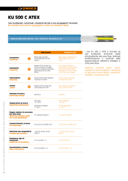
Energia e segnalamento / Power and signalling
Low voltage
Bassa tensione
FG7(O)R
0,6/1 kV
Norma di riferimento
CEI 20-13
Standard
CEI 20-13
Descrizione del cavo
Cable design
>
>
>
>
Anima
Conduttore a corda rotonda flessibile di rame rosso ricotto
Isolante
Gomma HEPR ad alto modulo, che conferisce al cavo elevate
caratteristiche elettriche, meccaniche e termiche (norme CEI
20-11 - CEI 20-34)
Colori delle anime
>
>
Core
Stranded flexible annealed bare copper conductor
Insulation
High module HEPR rubber, with higher electrical, mechanical and thermal
performances (CEI 20-11 - CEI 20-34 standards)
Core identification
black
nero
blu chiaro-marrone
blu chiaro-marrone-nero-grigio
giallo/verde-marrone-nero-grigio
>
>
light blue-brown-black-grey
yellow/green-brown-black-grey
giallo/verde
blu chiaro-marrone-nero-grigio
Le anime dei cavi per segnalamento sono nere, numerate ed
è previsto il conduttore di terra giallo/verde
Guaina
In PVC speciale di qualità Rz, colore grigio
Marcatura
Stampigliatura ad inchiostro speciale ogni 1 m:
CEI 20-22 II IEMMEQU CEI 20-52 <sigla di designazione
secondo tabelle CEI UNEL 35011> G-SETTE PIU’ <numero
di conduttori per sezione> PRYSMIAN (G) <anno> ECOLOGY
LINE or EASY LINE
Marcatura metrica progressiva
>
>
brown-black-grey
yellow/green-light blue-brown
yellow/green
light blue-brown-black-grey
Conductors for signalling cables are black, with numbers and with
yellow/green earth conductor
Sheath
Special PVC grey outer sheath, Rz type
Marking
Special ink marking each meter interval on the outer sheath:
CEI 20-22 II IEMMEQUCEI 20-52 <identification label according to CEI
UNEL 35011 tables> G-SETTE PIU’ <number of cores per cross-section>
PRYSMIAN (G) <year> ECOLOGY LINE or EASY LINE
Progressive metric marking
Conforme ai requisiti essenziali delle direttive BT73/23 e
93/68 CE
Compliant with the requirements of the BT73/23 and 93/68 CE
directives
Caratteristiche del cavo
Cable applications
>
Adatti per alimentazione e trasporto di comandi e/o segnali
nell’industria/artigianato e dell’edilizia residenziale. Adatti
per posa fissa sia all’interno, che all’esterno su passerelle,
in tubazioni, canalette o sistemi similari. Possono essere
direttamente interrati
90°C
250°C
TEMPERATURA
FUNZIONAMENTO
OPERATING
TEMPERATURE
TEMPERATURA
CORTOCIRCUITO
SHORT-CIRCUIT
TEMPERATURE
>
For supply and feeding of power and signals in industry, public applications
and residential buildings. Suitable for fixed installation both indoor and
outdoor, on cable trays, in pipe, conduits or similar systems. Can be
directly buried
Pb
CEI 20-35
EN 60332
CEI 20.22 II
CEI 20-37
EN 50267
SENZA
PIOMBO
LEAD
FREE
TEMPERATURA
MINIMA DI POSA
0 °C
MINIMUM
INSTALLATION
TEMPERATURE
0 °C
TUBO O
CANALINA IN ARIA
DUCT OR
CABLE TRAY
FLESSIBILE
FLEXIBLE
EASY LINE
LAYING CONDITIONS
CONDIZIONI DI POSA
22
light blue-brown
marrone-nero-grigio
giallo/verde-blu chiaro-marrone
CANALE
INTERRATO
BURIED
TROUGH
TUBO
INTERRATO
BURIED
DUCT
ARIA LIBERA
OPEN AIR
INTERRATO CON
PROTEZIONE
BURIED
WITH PROTECTION
LI
A
CE
I-U
NE
L
IS
A'
LI T
UA
TI
TU
TO
Q
DI
ITA
O
HI
RC
NO
MA
CO
E
M
OR
NF
NO
RM
E
VO
CA
Ecology
LineTM
FG7(O)R
sezione
nominale
diametro
indicativo
conduttore
conductor approximate
cross-section diameter,
conductor of
the phase
core
2
(mm )
(mm)
spessore
medio
isolante
average
insulation
thickness
diametro
esterno
massimo
maximum
outer
diameter
peso
indicativo
del cavo
approximate
weight
(mm)
(mm)
(kg/km)
1 conduttore
1,5
2,5
4
6
10
16
25
35
50
70
95
120
150
185
240
300
400
1,5
1,9
2,4
3
4,1
5,2
6,3
7,7
9,4
10,9
12,7
14,5
15,6
17,8
20
23,1
26,7
0,7
0,7
0,7
0,7
0,7
0,7
0,9
0,9
1
1,1
1,1
1,2
1,4
1,6
1,7
1,8
2
6,7
7,2
7,8
8,4
9,4
10,4
12,2
13,6
15,4
17,3
19,4
21,4
23,8
26,0
29,2
32
36,5
51
65
80
105
150
200
300
390
540
740
940
1200
1480
1830
2340
2950
3850
1,5
1,9
2,4
3
4,1
5,2
6,3
7,7
9,4
1,5
1,9
2,4
3
4,1
5,2
6,3
7,7
9,4
10,9
12,7
14,5
15,6
24
33
45
58
80
107
135
169
207
268
328
383
444
510
607
703
823
20
28
37
48
66
88
117
144
175
222
269
312
355
417
490
-
0,7
0,7
0,7
0,7
0,7
0,7
0,9
0,9
1
12
13
14,2
15,4
17,3
19,4
23
25,7
29,3
150
190
240
310
440
600
850
1130
1580
13,3
7,98
4,95
3,30
1,91
1,21
0,780
0,554
0,386
26
36
49
63
86
115
149
185
225
22
30
40
51
69
91
119
145
175
22
29
37
47
63
82
108
132
166
204
242
274
324
364
427
484
564
21
27
35
44
59
77
100
121
150
184
217
251
287
323
379
429
500
35
45
58
73
97
125
160
191
226
277
331
377
420
476
550
620
700
12,5
13,6
14,9
16,2
18,2
20,6
24,5
27,3
31,2
35,6
40
44,4
49,5
170
220
280
370
530
740
1060
1420
1960
2700
3430
4390
5400
13,3
7,98
4,95
3,30
1,91
1,21
0,780
0,554
0,386
0,272
0,206
0,161
0,129
23
32
42
54
75
100
127
158
192
246
298
346
399
19,5
26
35
44
60
80
105
128
154
194
233
268
300
32
39
51
64
85
110
141
169
199
244
292
332
370
419
484
546
616
30
30
35
40
40
45
55
60
65
75
85
90
100
110
120
140
150
2 cores
24
31
41
52
70
92
118
145
180
23
30
39
49
66
86
111
136
168
36
47
61
77
105
136
177
212
252
31
41
55
68
92
120
156
185
221
50
55
60
65
75
85
100
110
120
3 cores
tab. CEI-UNEL 35375
0,7
0,7
0,7
0,7
0,7
0,7
0,9
0,9
1
1,1
1,1
1,2
1,4
(mm)
single core
tab. CEI-UNEL 35375
3 conduttori
1,5
2,5
4
6
10
16
25
35
50
70
95
120
150
13,3
7,98
4,95
3,30
1,91
1,21
0,780
0,554
0,386
0,272
0,206
0,161
0,129
0,106
0,0801
0,0641
0,0486
raggio
minimo di
curvatura
minimum
bending
radius
ρ=1 °C m/w ρ=1,5 °C m/w ρ=1 °C m/w ρ=1,5 °C m/w
(Ω/km)
tab. CEI-UNEL 35375
2 conduttori
1,5
2,5
4
6
10
16
25
35
50
portata di corrente (A) con temperatura ambiente di
resistenza
massima a
30 °C in
30 °C in
20 °C
20 °C
20 °C in c. c.
aria
tubo in aria
interrato in tubo
interrato
maximum DC
permissible current rating (A)
resistance at in open air
In buried duct
in duct
buried
20 °C
at 20 °C
at 30 °C
at 30 °C
at 20 °C
20
26
33
43
59
76
100
122
152
189
226
260
299
19
25
32
41
55
72
93
114
141
174
206
238
272
30
40
51
65
88
114
148
178
211
259
311
355
394
26
36
45
56
78
101
130
157
185
227
274
311
345
50
55
60
65
80
90
100
110
130
150
170
190
200
Note: Le portate dei cavi unipolari sono state calcolate per tre cavi a trifoglio. Le portate dei cavi interrati sono state calcolate considerando una profondità di posa di 0,8 m.
Current carrying capacities for single core cables are calculated assuming three cables laying in trefoil formation. Current carrying capacities for buried cables are 23
calculated assuming a laying depth of 0.8 m.
Energia e segnalamento / Power and signalling
0,6/1 kV
FG7(O)R
diametro
indicativo
conduttore
conductor approximate
cross-section diameter,
conductor of
the phase
core
(mm2)
(mm)
sezione
nominale
spessore
medio
isolante
average
insulation
thickness
diametro
esterno
massimo
maximum
outer
diameter
peso
indicativo
del cavo
approximate
weight
(mm)
(mm)
(kg/km)
3 conduttori con giallo/verde
1,5
2,5
4
6
10
16
25
35
50
70
95
120
150
1,5
1,9
2,4
3
4,1
5,2
6,3
7,7
9,4
10,9
12,7
14,5
15,6
0,7
0,7
0,7
0,7
0,7
0,7
0,9
0,9
1
1,1
1,1
1,2
1,4
12,5
13,6
14,9
16,2
18,2
20,6
24,5
27,3
31,2
35,6
40
44,4
47,5
1,5
2,5
4
6
10
16
25
35+1X25
50+1X25
70+1X35
95+1X50
120+1X70
150+1X95
1,5
1,9
2,4
3
4,1
5,2
6,3
7,7
9,4
10,9
12,7
14,5
15,6
170
220
280
370
530
740
1060
1420
1960
2700
3430
4390
5400
1,5
1,9
2,4
3
4,1
5,2
6,3
7,7
9,4
10,9
12,7
14,5
15,6
0,7
0,7
0,7
0,7
0,7
0,7
0,9
0,9
1
1,1
1,1
1,2
1,4
13,4
14,6
16
17,5
19,8
22,4
26,8
29,2
32,4
37
42
46,9
52,5
200
260
330
430
640
900
1300
1650
2200
3000
3900
4700
6300
1,5
1,9
2,4
3
4,1
5,2
6,3
7,7
9,4
26
36
49
63
86
115
149
185
225
289
352
410
473
22
30
40
51
69
91
119
146
175
221
265
305
334
0,7
0,7
0,7
0,7
0,7
0,7
0,9
0,9
1
1,1
1,1
1,2
1,4
13,4
14,6
16
17,5
19,8
22,4
26,8
29,2
32,4
37
42
46,9
52,5
0,7
0,7
0,7
0,7
0,7
0,7
0,9
0,9
1
14,4
15,6
17,3
18,9
21,5
24,4
29,3
34,8
38,2
13,3
7,98
4,95
3,30
1,91
1,21
0,780
0,554
0,386
0,272
0,206
0,161
0,129
23
32
42
54
75
100
127
158
192
246
298
346
399
19,5
26
35
44
60
80
105
128
154
194
233
268
300
200
260
330
430
640
900
1300
1650
2200
3000
3900
4700
6300
13,3
7,98
4,95
3,30
1,91
1,21
0,780
0,554
0,386
0,272
0,206
0,161
0,129
23
32
42
54
75
100
127
158
192
246
298
346
399
19,5
26
35
44
60
80
105
128
154
194
233
268
300
24
31
41
52
70
92
118
145
180
223
265
310
356
23
30
39
49
66
86
111
136
168
207
245
284
324
36
47
61
77
105
136
177
212
252
310
371
423
472
13,3
7,98
4,95
3,30
1,91
1,21
0,780
0,554
0,386
23
32
42
54
75
100
127
158
192
19,5
26
35
44
60
80
100
128
154
31
41
55
68
92
120
156
185
221
272
325
370
414
50
55
60
65
80
90
100
110
130
150
170
190
200
4 cores
20
26
33
43
59
76
100
122
152
189
226
260
299
19
25
32
41
55
72
93
114
141
174
206
238
272
30
40
51
65
88
114
148
178
211
259
311
355
394
26
36
45
56
78
101
130
157
185
227
274
311
345
55
60
65
70
85
95
110
120
140
160
180
200
200
4 cores with yellow/green
20
26
33
43
59
76
100
122
152
189
226
260
299
19
25
32
41
55
72
93
114
141
174
206
238
272
30
40
51
65
88
114
148
178
211
259
311
355
394
26
36
45
56
78
101
130
157
185
227
274
311
345
55
60
65
70
85
95
110
120
140
160
180
200
200
5 cores with yellow/green
tab. CEI-UNEL 35375
230
310
400
520
780
1120
1680
2150
3000
(mm)
3 cores with yellow/green
tab. CEI-UNEL 35375
5 conduttori con giallo/verde
1,5
2,5
4
6
10
16
25
35
50
13,3
7,98
4,95
3,30
1,91
1,21
0,780
0,554
0,386
0,272
0,206
0,161
0,129
raggio
minimo di
curvatura
minimum
bending
radius
ρ=1 °C m/w ρ=1,5 °C m/w ρ=1 °C m/w ρ=1,5 °C m/w
(Ω/km)
tab. CEI-UNEL 35375
4 conduttori con giallo/verde
1,5
2,5
4
6
10
16
25
35+1G25
50+1G25
70+1G35
95+1G50
120+1G70
150+1G95
resistenza
portata di corrente (A) con temperatura ambiente di
30 °C in
30 °C in
20 °C
20 °C
massima a
aria
tubo in aria
interrato in tubo
interrato
20 °C in c. c.
maximum DC
permissible current rating (A)
resistance at in open air
buried
in buried duct
in duct
20 °C
at 30 °C
at 20 °C
at 20 °C
at 30 °C
tab. CEI-UNEL 35375
4 conduttori
24
Low voltage
Bassa tensione
20
26
33
43
59
76
100
122
152
19
25
32
41
55
72
93
114
141
30
40
51
65
88
114
148
178
211
26
36
45
56
78
101
130
157
185
60
65
70
75
95
100
130
140
160
Note: Le portate dei cavi quadripolari e pentapolari sono state calcolate per tre conduttori attivi. Le portate dei cavi interrati sono state calcolate considerando una
profondità di posa di 0,8 m.
Current carrying capacities for cables consisting of 4/5 conductors are calculated assuming three working conductors. Current carrying capacities for buried cables
are calculated assuming a laying depth of 0.8 m.
LI
A
CE
I-U
NE
L
IS
A'
LI T
UA
TI
TU
TO
Q
DI
ITA
O
HI
RC
NO
MA
CO
E
M
OR
NF
NO
RM
E
VO
CA
COMANDO E SEGNALAMENTO
numero
conduttori
number
of cores
(n)
spessore
medio
isolante
average
insulation
thickness
diametro
esterno
massimo
maximum
outer
diameter
peso
indicativo
del cavo
approximate
weight
resistenza
massima a
20 °C in c. c.
maximum
DC resistance
at 20 °C
(mm)
(mm)
(mm)
(kg/km)
(Ω/km)
sezione 1,5 mm2
5G
7G
10 G
12 G
16 G
19 G
24 G
1,5
1,5
1,5
1,5
1,5
1,5
1,5
1,9
1,9
1,9
1,9
1,9
1,9
portata di corrente (A) con temperatura ambiente di
30 °C in
30 °C in
20 °C
tubo in aria
aria
interrato in tubo
permissible current rating (A)
in duct
in open air
in buried duct
at 30 °C
at 30 °C
at 20 °C
ρ=1 °C m/w
0,7
0,7
0,7
0,7
0,7
0,7
0,7
14,4
15,4
18,7
19,3
21,1
22,1
25,4
230
275
365
410
510
580
700
13,3
13,3
13,4
13,4
13,4
13,4
13,5
16
13
13
11
11
9
9
14
11,5
11,5
9,5
9,5
8
8
16,8
20,6
21,3
23,3
24,5
28,3
310
395
445
545
615
750
7,98
8,06
8,06
8,06
8,06
8,1
17,5
17,5
13,5
13,5
12
12
(mm)
26
18,5
18,5
14,5
14,5
13
13
23
16
16
12,5
12,5
11,5
11,5
90
100
110
120
130
130
150
2.5 mm2 cross-section
tab. CEI-UNEL 35377
0,7
0,7
0,7
0,7
0,7
0,7
ρ=1,5 °C m/w
raggio
minimo di
curvatura
minimum
bending
radius
1.5 mm2 cross-section
tab. CEI-UNEL 35377
sezione 2,5 mm2
7G
10 G
12 G
16 G
19 G
24 G
CONTROL AND SIGNALLING
FG7(O)R
diametro
indicativo
conduttore
approximate
diameter,
conductor of
the phase core
LineTM
Ecology
15,5
15,5
12
12
10,5
10,5
24
24
20
20
16
16
21
21
17,5
17,5
14
14
110
120
130
140
150
170
Note: Le portate dei cavi quadripolari e pentapolari sono state calcolate per tre conduttori attivi. Le portate dei cavi interrati sono state calcolate considerando una
profondità di posa di 0,8 m.
Current carrying capacities for cables consisting of 4/5 conductors are calculated assuming three working conductors. Current carrying capacities for buried cables 25
are calculated assuming a laying depth of 0.8 m.
Scarica