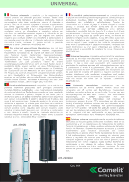
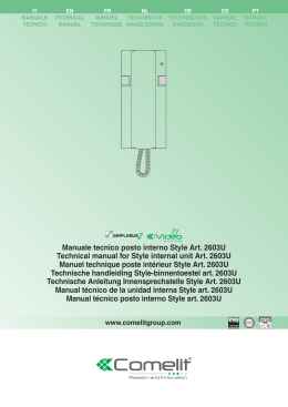
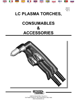
HEV28R
(Round)
English
Quick Install Guide
Guide d’installation rapide du Caisson
Guia de Instalación de la Carcasa
Guida di Installazione Rapida
Manual de Instalação Rápida
Kurzanleitung
Handleiding voor snelle installatie
Français
Español
Italiano
The HEV28R comprises a housing, a gimbal, and a quick change lens.
To complete the installation:
Le modèle HEV28R comporte un caisson, un cardan et un objectif à
changement rapide. Les étapes pour l’installation sont les suivantes :
La unidad HEV28R comprende una carcasa, un cardán y un lente de
cambio rápido. Para efectuar la instalación:
1.
2.
1.
2.
1.
2.
Install the housing. Follow the instructions in this guide.
Install the gimbal. Refer to the Gimbal Quick Install Guide that
comes with the gimbal (green box).
Install the lens. Refer to the Lens Quick Install Guide that comes
with the lens (blue box).
Secure the enclosure cover. Follow the instructions in this guide.
3.
4.
3.
4.
Important safeguards
Installez le caisson. Suivez les instructions figurant dans ce guide.
Installez le cardan. Pour ce faire, consultez le Guide d’installation
rapide du cardan, livré avec celui-ci (boîte verte).
Installez l’objectif. Pour ce faire, consultez le Guide d’installation
rapide de l’objectif, livré avec celui-ci (boîte bleue).
Fixez le couvercle du caisson. Suivez les instructions figurant
dans ce guide.
Il modello HEV28R è costituito da un alloggiamento, una sospensione
cardanica e un obiettivo a sostituzione rapida. Per completare
l’installazione:
Instale la carcasa siguiendo las instrucciones de esta guía.
Instale el cardán. Consulte la Guía de Instalación Rápida del
Cardán incluida con el cardán en la caja verde.
Instale el lente. Consulte la Guía de Instalación Rápida del Lente
incluida con el lente en la caja azul.
Asegure la cubierta de la caja protectora siguiendo las
instrucciones de esta guía.
3.
4.
1.
2.
3.
4.
Installation and servicing should be done by certified technicians to
conform to all local codes and to maintain your warranty.
THIS SYMBOL INDICATES THAT
DANGEROUS VOLTAGE
CONSTITUTING A RISK OF
ELECTRIC SHOCK IS PRESENT
WITHIN THE UNIT.
CAUTION
RISK OF ELECTRIC
SHOCK
DO NOT OPEN
Consignes importantes de sécurité
Precauciones importantes
L’installation et l’entretien doivent être effectués par des techniciens
agréés pour veiller au respect de tous les codes locaux et pour
maintenir vos droits à bénéficier de la garantie.
Para mantener la garantía vigente y cumplir con todos los códigos
locales, la instalación y el servicio a la unidad deben ser realizados sólo
por técnicos certificados.
ATTENTION
THIS SYMBOL INDICATES THAT
IMPORTANT OPERATING AND
MAINTENANCE INSTRUCTIONS
ACCOMPANY THIS UNIT.
CAUTION: TO REDUCE THE RISK OF ELECTRIC
SHOCK, DO NOT REMOVE THE COVER.
NO USER-SERVICEABLE PARTS INSIDE
REFER SERVICING TO QUALIFIED
SERVICE PERSONNEL
RISQUE DE CHOC
ÉLECTRIQUE.
NE PAS OUVRIR
CE SYMBOLE INDIQUE QU’À
L’INTERIEUR DE CETTE UNITÉ PASSE
UN COURANT DE TENSION
SUFFISAMMENT ÉLEVÉE POUR RISQUE
DE PROVOQUER UN CHOC
ÉLECTRIQUE.
ATTENTION: POUR RÉDUIRE LE RISQUE DE CHOC
ÉLECTRIQUE, NE RETIREZ PAS LE COUVERCLE.
AUCUNE PIÈCE DONT L’ENTRETIEN PEUT ÊTRE
ASSURÉ PAR L’UTILISATEUR NE SE TROUVE À
L’INTÉRIEUR. CONFIEZ LA MAINTENANCE À DES
TECHNICIENS QUALIFIÉS SPÉCIALISÉS DANS
L’ENTRETIEN
CE SYMBOLE INDIQUE QUE
D’IMPORTANTES INSTRUCTIONS
CONCERNANT LE FONCTIONNEMENT
ET LA MAINTENANCE ACCOMPAGNENT
CETTE UNITÉ.
Informazioni importanti per la
sicurezza
ESTE SÍMBOLO INDICA QUE
DENTRO DE ESTA UNIDAD HAY
TENSIÓN PELIGROSA QUE
PUEDE CAUSAR CHOQUES
ELÉCTRICOS.
CUIDADO
RIESGO DE CHOQUE
ELÉCTRICO.
NO LO ABRA.
PRECAUCIÓN: PARA REDUCIR EL RIESGO DE
CHOQUES ELÉCTRICOS, NO QUITE LA CUBIERTA.
EL MANTENIMIENTO Y EL SERVICIO DEBEN SER
HECHOS SÓLO POR PERSONAL CALIFICADO.
L’installazione e la manutenzione devono essere eseguite da tecnici
certificati per la conformità alle norme locali e per mantenere la validità
della garanzia.
ESTE SÍMBOLO INDICA QUE
INSTRUCCIONES IMPORTANTES
DE FUNCIONAMIENTO Y
MANTENIMIENTO ACOMPAÑAN
ESTA UNIDAD.
ATTENZIONE: PER RIDURRE IL RISCHIO DI SCOSSA
ÉLETTRICA, NON RIMUOVERE
LA COPERTURA. NON CONTIENE PARTI RIPARABILI
DALL’UTENTE. FARE ESEGUIRE LA MANUTENZIONE A
PERSONALE QUALIFICATO.
Figure 1
Conduit plug installation / Installation du bouchon de l’entrée des
câbles / Instalación del tapón del conducto / Installazione del tappo
del condotto del cavo
Back view / Vue arrière / Vista
posterior / Vista del retro
1
1
WARNING!
To minimize moisture leaking into the HEV28R housing,
position the enclosure with the conduit pointing down. Apply
an appropriate sealant around the conduit connection.
Note
Conduit plug
Bouchon de l’entrée des câbles
Tapón del conducto
Tappo condotto
2
1.
3.
Note
nt
Mou d
Wall mende
m
reco is way
th
Mounting screws (not
supplied)
Vis d’installation (non
fournier)
Tornillos de montaje (no
incluidos)
Viti di montaggio (non in
dotazione)
Pour réduire au maximum la condensation dans le caisson
du modèle HEV28R, installez-le de manière à ce que l’entrée
des câbles soit vers le bas. Appliquez ensuite un matériau
d’étanchéité approprié.
Alternate fasteners (preferably stainless steel) can be
used, provided they are not larger than the screw holes
on the mounting template.
Coaxial termination board / Carte de
terminaison coaxiale / Placa de terminación
coaxial / Scheda di collegamento coassiale
2
3
#$ !%
Audio
Audio
Figure 4
For direct connections to the termination board, it is
recommended that you route the cable using the cable
clamp supplied to restrain the cable (see Figure 4).
$
!
$
Potencia
Alimentazione
Case/ground
Caisson/mise à la
terre
Caja/tierra
Corpo/messa a terra
"
Video
Vidéo
Video
Video
used
# Not
Non utilisé
No se usa
Non utilizzato
Video cable connector / Branchement du câble vidéo / Conexión del
cable de video / Connettore cavo video
Power
supply
24
AWG
22
AWG
18
AWG
16
AWG
15 VDC
45/14
73/22
185/56
295/90
24 VAC
408/125
660/201
1674/510
2664/812
RG-59
RG-6
Wire gauge
23 AWG** 18 AWG** 14 AWG**
750/229
RG-11
1500/457
2000/610
Gimbal assembly connector / Connecteur de l’assemblage du
cardan / Conjunto del connector del cardán / Connettore della
sospensione cardanica
To base power board
Vers la carte d’alimentation de base
Hacia la placa base de potencia
Alla scheda di alimentazione della
base
Termination board
Carte de terminaison
Placa de terminación
Scheda di
collegamento
Installing the base power board / Installation de la carte
d’alimentation de base / Instalación de la placa base de potencia /
Installazione della scheda di alimentazione della base
Tab
Languette
Lengüeta
Linguetta
Note
AWG
250/
76
500/
152
1000/
305
1500/
457
2000/
610
3000/
914
18
3Ω
6Ω
13 Ω
19 Ω
26 Ω
40 Ω
20
5Ω
10 Ω
20 Ω
30 Ω
40 Ω
59 Ω
22
8Ω
17 Ω
33 Ω
48 Ω
66 Ω
99 Ω
24
13 Ω
26 Ω
52 Ω
78 Ω
108 Ω
163 Ω
Use point-to-point Unshielded Twisted Pair wire only.
5
Install the base power board
1.
3.
6
18
AWG
16
AWG
15 VDC
45/14
73/22
185/56
295/90
24 VAC
408/125
660/201
1674/510
2664/812
Remarque Les calculs sont basés sur le cas le plus défavorable, à savoir celui
d’une alimentation électrique linéaire non régulée. L’utilisation d’une
alimentation électrique régulée ou à découpage peut permettre d’augmenter la
longueur de câble. Honeywell recommande l’utilisation d’une alimentation de
classe 2, certifié CSA/homologué UL, pour assurer le respect des normes de
sécurité électrique. Longueur maximale des câbles vidéo coaxiaux (pieds/
mètres).
Edge of bracket
Bord de la ferrure
Borde de la ménsula
Bordo del supporto
2.
3.
7
Ensure the base power and video wiring is in place and the power
to the unit is turned off.
Plug the 8-pin camera assembly connector into the termination
board in the housing (see Figure 5).
The base power board has four horizontal tabs. Slide the two
horizontal tabs that are furthest from the power board wire
connector under the edges of the black bracket on the housing.
See Figure 6.
Each of the other two tabs should now be resting on a standoff
peg. Press the base power board firmly down onto the two
standoffs. Ensure the wires are not in the way.
3.
Opzioni di cablaggio
AVVERTENZA!
Si richiede l’utilizzo di alimentatori con certificazione CSA,
classificati UL, classe 2, per la conformità con gli standard
di sicurezza elettrica.
Conexiones de cableado
La videocamera HEV28R è dotata di tre diverse schede di collegamento
montate sulla parte inferiore dell’alloggiamento. Tutti i collegamenti
sono eseguiti qui. Vedere Figura 3 per le opzioni di cablaggio
selezionate.
Usted puede conectar el cable de video coaxial, UTP, o de fibra
directamente a la placa de terminación. También puede conectar el
cable flexible mini coaxial del BNC provisto con la cámara.
Nota
Para conexiones directas a la placa de terminación se
recomienda que tienda el cable utilizando la abrazadera
de cable provista para retenerlo en su lugar (vea la
Figura 4).
4
Collegamento cavi
È possibile collegare un cavo coassiale, UTP o un cavo video a fibre
ottiche direttamente alla scheda di collegamento. Inoltre, è possibile
collegare il cavo coassiale al mini filo connettore a spirale coassiale
BNC (in dotazione).
Pautas para cables
Nota
Máxima longitud para el cable de suministro de potencia (pies/metros)
Cámaras con suministro CA/CC
Calibre
Suministro
de potencia
AWG
24
AWG
22
AWG
18
AWG
16
15 VCC
45/14
73/22
185/56
295/90
24 VCA
408/125
660/201
1674/510
2664/812
Istruzioni per i cavi
Lunghezza massima cavo di alimentazione (metri)
Videocamere con alimentazione CA/c.c.
Nota
Los cálculos se basan en una alimentación lineal no regulado que sería
el peor escenario. Si utiliza una fuente de alimentación regulada, puede aumentar
la distancia del cable. Honeywell recomienda usar una fuente de alimentación
Certificada por CSA o Clase 2 de UL para asegurar el cumplimiento de las
normas de seguridad eléctricas.
Calibratura fili
Máxima longitud del cable coaxial de video (pies/metros)
Tipo de cable
RG-59
RG-6
RG-11
Alimentazione
elettrica
24
AWG
22
AWG
18
AWG
16
AWG
15V c.c.
45/14
73/22
185/56
295/90
24V CA
408/125
660/201
1674/510
2664/812
Calibre de fil
23 AWG**
18 AWG**
14 AWG**
** Núcleo de accro revestido de cobre, 95% blindaje de malla
750/229
1500/457
2000/610
Máxima longitud del cable UTP de video (pies/meters)
Lunghezza massima cavo video coassiale (metri)
Calibre
Distancia máxima
AWG
18
3Ω
6Ω
13 Ω
19 Ω
26 Ω
40 Ω
20
5Ω
10 Ω
20 Ω
30 Ω
40 Ω
59 Ω
22
8Ω
17 Ω
33 Ω
48 Ω
66 Ω
99 Ω
24
13 Ω
26 Ω
52 Ω
78 Ω
108 Ω
163 Ω
500/
152
1000/305 1500/457 2000/610 3000/914
Étapes suivantes
1.
2.
3.
Installez le cardan. Pour ce faire, consultez le Guide d’installation
rapide du cardan, livré avec celui-ci (boîte verte).
Installez l’objectif. Pour ce faire, consultez le Guide d’installation
rapide de l’objectif, livré avec celui-ci (boîte bleue).
Fixez le couvercle du caisson (voir la Figure 7).
2000/610
500/
152
18
3Ω
6Ω
13 Ω
19 Ω
26 Ω
40 Ω
20
5Ω
10 Ω
20 Ω
30 Ω
40 Ω
59 Ω
22
8Ω
17 Ω
33 Ω
48 Ω
66 Ω
99 Ω
24
13 Ω
26 Ω
52 Ω
78 Ω
108 Ω
163 Ω
Nota
5
1000/305 1500/457 2000/610 3000/914
Tipo di cavo
Calibratura fili
Lunghezza massima
Instale la placa base de potencia
1.
Verifique que la placa base de potencia y el cableado de video
están en su lugar y que la potencia a la unidad está apagada.
Enchufe el conector de 8 pines del conjunto de la cámara en el
panel de terminación de la carcasa (vea la Figura 5).
La placa base de potencia base tiene cuatro lengüetas
horizontales. Deslice las dos lengüetas horizontales que están
situadas más apartadas del conector de cable debajo de los
bordes de la ménsula negra en la carcasa. Vea la Figura 6.
Ahora las dos lengüetas restantes deben haber quedado
descansando en una clavija de soporte. Oprima la placa base de
potencia firmemente sobre lo dos soportes. Confirme que los
alambres no están interfiriendo.
2.
3.
7
Deslice la bisagra hacia la base hasta que los tornillos queden
alineados con sus correspondientes agujeros. Asegure la cubierta
atornillándola en su lugar.
18 AWG**
14 AWG**
750/229
1500/457
2000/610
Lunghezza massima (metri)
AWG
250/76
500/152
18
3Ω
6Ω
13 Ω
19 Ω
26 Ω
40 Ω
20
5Ω
10 Ω
20 Ω
30 Ω
40 Ω
59 Ω
22
8Ω
17 Ω
33 Ω
48 Ω
66 Ω
99 Ω
13 Ω
26 Ω
52 Ω
78 Ω
108 Ω
163 Ω
24
Nota
5
3.
4.
3.
7
Assicurarsi che le connessioni dei cavi di alimentazione e video
siano corrette e che l’alimentazione elettrica dell’unità sia
disattivata.
Collegare il connettore del gruppo camera a 8-pin nella scheda di
collegamento dell’alloggiamento (vedere Figura 5).
La scheda di alimentazione della base è dotata di quattro linguette
in posizione orizzontale. Far scorrere le due linguette orizzontali
che si trovano più distanti dal connettore del cavo della scheda di
alimentazione al di sotto dei bordi del supporto nero presente
sull’alloggiamento. Vedere Figura 6.
Ciascuna delle altre linguette deve essere posizionata su un
dentino di supporto. Premere saldamente la scheda di
alimentazione della base sui due dentini di supporto. Assicurarsi
che i cavi non siano di intralcio per l’esecuzione di questa
operazione.
Passaggi successivi
1.
Fixer le couvercle du caisson
3000/914
Installazione della scheda di
alimentazione della base
1.
6
1000/305 1500/457 2000/610
Utilizzare solo un cavo a coppia intrecciata punto a punto.
2.
Faites glisser la charnière vers la base jusqu’à ce que les vis s’alignent
avec les trous des vis. Fixez le couvercle.
23 AWG**
Nota
Si consiglia di misurare la distanza del cavo per evitare di superare la
capacità del cavo a coppia intrecciata. È possibile calcolare la resistenza del cavo
con un ohmetro cortocircuitando i due conduttori insieme alle estremità e
calcolando quindi la resistenza in loop di entrata di ritorno. Eseguire un confronto
seguendo la tabella riportata.
Instale el cardán. Consulte la Guía de Instalación Rápida del
Cardán incluida con el cardán en la caja verde.
Instale el lente. Consulte la Guía de Instalación Rápida del Lente
incluida con el lente en la caja azul.
Asegure la cubierta en su lugar siguiendo las indicaciones a
continuación (vea la Figura 7).
Asegure la cubierta
RG-11
Honeywell consiglia i seguenti ricetrasmettitori video NVT (venduti separatamente
tramite NVT Inc.):
•
NV-212A (152 m—26 Ω)***
•
NV-213A/A-M (305 m—52 Ω)***
•
NV-652R, NV-862R o NV-1662R (914 m—163 Ω)***
*** Le distanze sono state calcolate in base al cavo a coppia intrecciata 24 AWG.
Pasos siguientes
1.
RG-6
Lunghezza massima cavo video UTP (metri)
2.
6
RG-59
** Anima di acciaio con rivestimento in rame, 95% protezione intrecciata
Use sólo cable de par trenzado, sin blindaje, de punto a punto.
4.
4.
1500/457
250/
76
1.
Secure the enclosure cover
750/229
AWG
3.
3.
14 AWG**
Longitud máxima (pies/metros)
Installation de la carte
d’alimentation de base
2.
18 AWG**
Nota
Se recomienda medir la distancia del cable para asegurar que no va a
exceder la capacidad del cable de par trenzado. La resistencia del cable se puede
medir con un ohmetro cortocircuitando los dos conductores al mismo tiempo en
el extremo alejado y luego midiendo la resistencia del bucle de ida y de vuelta.
Compare el resultado con la siguiente tabla.
2.
Assurez-vous que le câblage de l’alimentation de base et le
câblage vidéo sont en place et que l’unité est mise hors tension.
Branchez le connecteur à 8 broches de l’assemblage de la
caméra sur la carte de terminaison située dans le caisson (voir la
Figure 5).
La carte d’alimentation de base comporte quatre languettes
horizontales. Faites glisser les deux languettes horizontales qui
sont les plus éloignées du capuchon de connexion de la carte
d’alimentation sous les bords du support noir sur le caisson. Voir
la Figure 6.
Chacun des deux autres onglets devraient maintenant reposer sur
une cheville. Enfoncez fermement la carte d’alimentation de base
sur les deux chevilles. Assurez-vous que les câbles ne sont pas
dans le chemin.
23 AWG**
Honeywell recomienda los siguientes transceptores NVT (vendidos por NVT Inc
por aparte):
•
NV-212A (500 pi/152 m—26 Ω)***
•
NV-213A/A-M (1000 pi/305 m—52 Ω)***
•
NV-652R, NV-862R or NV-1662R (3000 pi/914 m—163 Ω)***
*** Las distancias han sido calculadas usando un cable de par trenzado 24 AWG.
Remarque Utilisez uniquement un fil UTP point à point.
7
Per i collegamenti diretti sulla scheda di collegamento, si
consiglia di posizionare il cavo utilizzando il morsetto del
cavo per bloccarlo correttamente (vedere Figura 4).
RG-11
250/
76
6
3
RG-6
Remarque Les longueurs ont été calculées en utilisant un fil à paire torsadée de
calibre 24 AWG.Nous vous recommandons de mesurer la longueur du fil afin de
vous assurer que le système n’excède pas les capacités du produit à paire
torsadée. Vous pouvez mesurer la résistance du fil à l’aide d’un ohmmètre en courtcircuitant les deux conducteurs à l’extrémité distante, puis en mesurant la
résistance de la boucle dans un sens puis dans l’autre. Comparez vos résultats au
tableau suivant.
Slide the hinge towards the base until the screws align with the screw
holes. Secure the cover in place.
È possibile utilizzare dispositivi di fissaggio alternativi
(preferibilmente in acciaio inossidabile), ma solo se non
risultano di dimensioni maggiori rispetto ai fori presenti
sul modello di montaggio.
RG-59
Honeywell recommande l’utilisation des émetteurs-récepteurs vidéo NVT suivants
(vendus séparément par NVT Inc.):
•
NV-212A (500 pi/152 m—26 Ω)***
•
NV-213A/A-M (1000 pi/305 m—52 Ω)***
•
NV-652R, NV-862R or NV-1662R (3000 pi/914 m—163 Ω)***
*** Les longueurs ont été calculées en utilisant un fil à paire torsadée de calibre
24 AWG.
Install the gimbal. Refer to the Gimbal Quick Install Guide that
comes with the gimbal (green box).
Install the lens. Refer to the Lens Quick Install Guide that comes
with the lens (blue box).
Secure the enclosure cover (see Figure 7).
Nota
Type de câble
Longueur maximale des câbles vidéo UTP (pieds/mètres)
5
2.
Nota
I calcoli si basano sull’alimentazione lineare non regolata, che
rappresenta il caso peggiore. L’utilizzo di alimentazione regolata o a commutazione
consente di aumentare la distanza del cavo. Honeywell consiglia l’utilizzo di
alimentatori con certificazione CSA, classificati UL, classe 2, per la conformità
con gli standard di sicurezza elettrica.
Longeur maximale
Next steps
1.
Enclosure cover / Couvercle du caisson / Cubierta de la caja
protectora / Copertura involucro
22
AWG
Longueur maximale (pieds/metres)
4.
Figure 7
24
AWG
** Âme d’acier recouvert de cuivre, blindage tressé à 95%
Bracket
Ferrure
Ménsula
Supporto
Tab
Languette
Lengüeta
Linguetta
Type
d’alimentation
Note
We recommend that you measure the wire distance to ensure that the
capability of the twisted pair product is not exceeded. You can measure wire
resistance with an ohmmeter by shorting the two conductors together at the far
end, then measuring the loop resistance out and back. Compare against the
following table.
2.
Base power board
Carte d’alimentation de base
Placa base de potencia
Scheda di alimentazione della base
Branchement des câbles
Longueur maximale des câbles vidéo coaxiaux (pieds/mètres)
Connector
Connecteur
Conector
Connettore
Fissare il modello di montaggio (in dotazione) sulla superficie di
montaggio (vedere Figura 2).
Eseguire una perforazione preliminare di quattro fori, come
indicato sul modello, utilizzando la dimensione foro consigliata
per le viti.
Se necessario, eseguire la perforazione del foro per il condotto.
La cámara HEV28R puede venir con una de dos placas de terminación
diferentes en el fondo de la carcasa. Todas las conexiones se hacen
ahí. Vea la Figura 3 para la opción de cableado que ha seleccionado.
4
Honeywell recommends the following NVT video transceivers (sold separately
through NVT Inc.):
•
NV-212A (500 ft/152 m—26 Ω)***
•
NV-213A/A-M (1000 ft/305 m—52 Ω)***
•
NV-652R, NV-862R or NV-1662R (3000 ft/914 m—163 Ω)***
*** Distances have been calculated using 24 AWG Twisted Pair wire.
Maximum length (feet/meters)
Guida all’installazione
1.
Opciones de cableado
Es imprescindible utilizar una alimentación de potencia
Clase 2 certificada por CSA o listado por UL para cumplir
con las normas eléctricas de seguridad.
Calibre de fil
Cable type
2
Se non viene utilizzato un condotto per il cablaggio,
installare l’anello in gomma nel foro del condotto, quindi
fare in modo che i cavi passino attraverso l’apertura
dell’anello. Sigillare l’anello per evitare che l’umidatà
penetri nell’alloggiamento.
¡ADVERTENCIA!
Longueur maximale des câbles d’alimentation électrique (pieds/mètres)
Caméras dotées d’une alimentation électrique ca/cc
Coaxial video cable maximum length (feet/meters)
Nota
Options de càblage
Directives concernant les câbles
Note
Calculations are based on an unregulated linear power supply which
would be the worst case. Using a regulated or switching power supply can increase
the cable distance. Honeywell recommends using a CSA Certified/UL listed Class
2 power supply to ensure compliance with electrical safety standards.
Per ridurre la formazione di umidità nell’alloggiamento
HEV28R, posizionare la copertura con il condotto diretto
verso il basso. Applicare del materiale sigillante adeguato
intorno alla connessione del condotto.
Se pueden utilizar otro tipo de sujetadores,
preferiblemente de acero inoxidable, siempre y cuando
no sean más grandes que los orificios en la plantilla de
montaje.
Remarque Pour les branchements directs sur la carte de terminaison, il est recommandé de fixer le tracé du câble en utilisant le collier de serrage prévu pour l’immobiliser (voir
la Figure 4).
UTP video cable maximum length (feet/meters)
Termination board
Carte de terminaison
Placa de terminación
Scheda di
collegamento
Si no se utiliza un conducto para dirigir el cable, monte
la arandela de goma en el orificio del conducto, deslícela
e introduzca el cable a trafés de ésta. Selle la arandela
para impedir la entrada de humedad en la carcasa.
Nota
Vous pouvez brancher votre câble vidéo coaxial, UTP ou fibre optique
directement sur la carte de terminaison. Vous pouvez également
brancher le câble coaxial sur le mini-câble coax BNC sans connecteur.
** Copper clad steel core, 95% braided shield
Figure 6
3.
Wire gauge
! Power
Alimentation
Note To remove the connector,
depress the clip and pull up from
the board.
Remarque Pour enlever le
connecteur, appuyez sur le clip et
retirez-le de la carte.
Nota Para sacar el conector
oprima el clip y tire de él
separàndolo de la placa.
Nota Per scollegare il connetore,
premere la linguetta e quindi
estrarre dalla scheda.
4
Cable guidelines
Maximum length
Figure 5
2.
Apposez le gabarit de montage (fourni) sur la surface de montage
(voir la Figure 2).
Préperforez quatre trous comme indiqué sur le gabarit, en
respectant la taille de trou recommandée pour les vis utilisées.
Au besoin, perforez un trou de conduit.
Votre caméra HEV28R est fournie avec trois cartes différentes de
raccordement à circuit imprimé, dont l’une est installée dans le bas du
caisson. Tous les branchements s’effectuent à ce niveau. Voir la
Figure 3 pour les options de câblage.
Power supply cable maximum length (feet/meters)
Cameras with AC/DC power supplies
Fiber termination board with ST
connector / Carte de
terminaison pour fibre optique
avec connecteur standard /
Fiber termination board with ST
connector SP / Scheda di
collegamento a fibre ottiche con
connettore ST
% Audio
Audio
#$ ! %
"
Sul retro, la copertura della videocamera HEV28R è dotata di un tappo
del condotto cavo preinstallato nell’entrata del condotto con dimensioni
pari a ½". È possibile rimuovere e installare questo tappo sul lato
dell’entrata condotto con dimensioni pari a ¾" (vedere Figura 1).
Coloque la plantilla de montaje provista en la superficie donde va
a colocar la unidad (vea la Figura 2).
Taladre cuatro agujeros en los puntos indicados en la plantilla,
utilizando el tamaño de agujero recomendado para los tornillos
que se van a utilizar.
Taladre el agujero para el conducto, si se necesita.
Vous devez utiliser un adaptateur de courant de classe 2,
certifié CSA/homologué UL, pour assurer le respect des
normes de sécurité sur l’électricité.
You can connect your coaxial, UTP, or fiber video cable directly to the
termination board. You can also connect the coaxial cable to the mini
coax BNC pigtail (supplied).
"
Para evitar en lo posible las infiltraciones de humedad en la
carcasa de la HEV28R selle la entrada del cable con un
sellador apropiado y posicióne el conduit apuntando nacia
abajo.
Guía de montaje
MISE EN GARDE!
Wiring connections
Note
2
3
Your HEV28R camera is supplied with one of three different termination
boards mounted to the bottom of the housing. All connections are made
here. See Figure 3 for the wiring option you have selected.
4
¡PRECAUCIÓN!
Remarque D’autres types d’attaches (de préférence en acier inoxydable) peuvent être utilisées du moment qu’elles ne
sont pas plus grosses que les trous prévus sur le
gabarit d’installation.
WARNING!
1
AVVERTENZA!
1.
3.
Aprire la confezione. Verificare che gli elementi ricevuti corrispondano a
quelli elencati nel modulo d’ordine e nel tagliando della confezione.
Oltre a questa Guida di installazione rapida, la scatola
dell’alloggiamento HEV28R deve comprendere quanto elencato di
seguito:
•
Un involucro HEV28R
•
Un modello di montaggio
•
Un kit hardware
•
Una scheda di garanzia del prodotto
Nel caso di parti mancanti o danneggiate, rivolgersi al rivenditore
presso il quale è stata acquistata l’unità o chiamare il Servizio clienti di
Honeywell.
Installazione del tappo del condotto
cavo
Nota
Schéma de montage
1.
Wiring options
Wiring options / Options de câblage / Opciones de cableado /
Opzioni di cablaggio
UTP termination board / Carte de
terminaison UTP / Placa de terminación
UTP / Scheda di collegamento UTP
Remarque Si un conduit n’est pas utilisé pour le cheminement du
âblage, il est nécessaire d’installer le passe-fil en
caoutchouc dans le trou de conduit, puis d’ouvrir le
passe-fil avant de passer le câblage. Assurez-vous de
l’étanchéité du passe-fil afin d’éviter toute pénétration
d’humidité dans le caisson.
2.
3
La caja de protección de la cámara HEV28R viene con un tapón
preinstalado en la entrada para el conducto de ½ pulgada situada en la
parte posterior. Este tapón se puede sacar e instalar en la entrada
lateral del conducto de ¾ pulgada (vea la Figura 1).
QUESTO SIMBOLO INDICA CHE
L’UNITÀ È ACCOMPAGNATA DA
IMPORTANTI INFORMAZIONI PER
L’USO E LA MANUTENZIONE.
Prima di iniziare
Instale el tapón del conducto
MISE EN GARDE!
The use of a CSA Certified/UL Listed Class 2 power supply is
required to ensure compliance with electrical safety
standards.
Figure 3
Installation du bouchon de l'entrée
des câbles
If a conduit is not used for cable routing, install the
rubber grommet in the conduit hole, then slit the
grommet and feed the wiring through. Seal the
grommet to prevent moisture from entering the
housing.
Affix the mounting template (supplied) to the mounting surface
(see Figure 2).
Pre-drill four holes as indicated on the template, using the
recommended hole size for the screws being used.
Drill out conduit hole, if required.
2.
1
Le caisson de votre caméra HEV28R est livré avec un bouchon d’entrée
des câbles préinstallé dans le conduit d’arrivée des câbles de ½ pouce,
à l’arrière. Vous pouvez retirer ce bouchon et l’installer dans le conduit
d’arrivée des câbles latéral de ¾ de pouce (voir la Figure 1).
Mounting guide
Mounting template guide / Instructions pour le gabarit de montage /
Instalación del tapón del conducto / Guida modello di montaggio
Desempaque todo. Confirme que los artículos recibidos corresponden
a los indicados en el formulario de pedido y la lista de empaque. La
caja del HEV28R debe incluir, además de esta Guía de Instalación
Rápida:
•
Una caja de protección para la cámara HEV28R
•
Una plantilla de montaje
•
Ferretería
•
Una tarjeta de Garantía de Producto
Si hacen falta partes o si hay partes dañadas, contacte al distribuidor
donde compró la cámara o llame al departamento de Atención a
Clientes de Honeywell.
Déballez l’ensemble des éléments. Vérifiez que les articles reçus
correspondent à ceux répertoriés sur le bon de commande et sur le
bordereau d’emballage. La boîte du caisson du HEV28R doit
comprendre, en plus de ce guide d’installation rapide :
•
Un caisson HEV28R
•
Un gabarit de montage
•
Un jeu de pièces
•
Une carte de garantie du produit
Si certaines pièces manquent ou sont endommagées, contactez le
distributeur auprès duquel vous avez acheté la caméra ou appelez le
service clientèle de Honeywell.
Your HEV28R camera enclosure comes with a conduit plug pre-installed
in the 1/2 inch conduit entry on the back. This plug may be removed
and installed in the side 3/4 inch conduit entry (see Figure 1).
Retainer plate
Plaque de
retenue
Placa de
retención
Piastra di blocco
Gasket
Joint statique
Sello
Anello di tenuta
Instructions préliminaires
Install the conduit plug
Side view / Vue latérale / Vista
lateral / Vista laterale
Screw
Vis
Tornillo
Vite
Figure 2
Antes de comenzar
Unpack everything. Check that the items received match those listed on
the order form and packing slip. The HEV28R housing box should
include, in addition to this Quick Install Guide:
•
One HEV28R enclosure
•
One mounting template
•
One hardware kit
•
One Product Warranty card
If any parts are missing or damaged, contact the dealer you purchased
the camera from or call Honeywell Customer Service.
QUESTO SIMBOLO INDICA LA
PRESENZA DI TENSIONI
PERICOLOSE ALL’INTERNO
DELL’UNITÀ; RISCHIO DI
SCOSSA ÉLETTRICA.
ATTENZIONE
RISCHIO DI SCOSSA
ÉLETTRICA
NON APRIRE
Before you begin
Figures
Installare l’alloggiamento. Seguire le istruzioni riportate in questa
guida.
Installare la sospensione cardanica. Fare riferimento alla Guida di
installazione rapida della sospensione cardanica in dotazione con
la sospensione cardanica (scatola verde).
Installare l’obiettivo. Fare riferimento alla Guida di installazione
rapida dell’obiettivo in dotazione con l’obiettivo (scatola blu).
Fissare la copertura dell’involucro. Seguire le istruzioni riportate in
questa guida.
Installare la sospensione cardanica. Fare riferimento alla Guida di
installazione rapida della sospensione cardanica in dotazione con
la sospensione cardanica (scatola verde).
Installare l’obiettivo. Fare riferimento alla Guida di installazione
rapida dell’obiettivo in dotazione con l’obiettivo (scatola blu).
Fissare la copertura dell’involucro (vedere Figura 7).
Fissare la copertura dell’involucro
Far scorrere la cerniera in direzione della base fino ad allineare le viti
con i relativi fori. Bloccare la copertura in posizione.
Figures
Figure 1
Português
Instalação do tampão do passa-fios / Abdichtstöpsel für Kabelkanal
/ Het aanbrengen van een leidingplug
Vista de trás / Rückansicht /
Achteraanzicht
Vista lateral / Seitenansicht /
Zijaanzicht
A câmara HEV28R é composta por um alojamento, um cardan e uma
objectiva de substituição rápida. Para efectuar a instalação:
Das Modell HEV28R besteht aus einem Gehäuse, einem Kardan und
einem Schnellwechsel-Objektiv. So führen Sie den Einbau durch:
De HEV28R omvat een behuizing, een cardanische ophanging en een
snel verwisselbare lens. Om de installatie volledig te maken:
1.
2.
1.
1.
2.
Instale o alojamento. Siga as instruções indicadas neste manual.
Instale o cardan. Consulte o Manual de Instalação Rápida do
Cardan fornecido com o cardan (caixa verde).
Instale a objectiva. Consulte o Manual de Instalação Rápida da
Objectiva fornecido com a objectiva (caixa azul).
Fixe a tampa da caixa. Siga as instruções indicadas neste
manual.
3.
4.
Parafuso
Schraube
Schroef
Placa de
retenção
HalterungsPlatte
Blokkeerring
2.
3.
4.
Aviso importante
Figure 2
Tampão do passa-fios
Abdichtstöpsel für Kabelkanal
Leidingplug
CUIDADO: PARA REDUZIR O RISCO DE CHOQUES
ELÉCTRICOS, NÃO REMOVA A TAMPA (OU A
PARTE DE TRÁS). NÃO EXISTEM NO INTERIOR
PEÇAS QUE POSSAM SER REPARADAS PELO
UTILIZADOR. TODA A MANUTENÇÃO DEVE SER
EFECTUADA POR PESSOAL QUALIFICADO.
Guia de montagem / Anleitung für die Montageschablone /
Montagemal handleiding
Opções de ligações / Optionen zur Leitungsführung / Mogelijke
bedrading
Placa de conexão UTP / UTP-Klemmbrett /
UTP aansluitkaart
1
VORSICHT
Placa de conexão de fibra com
conector padrão /
Glasfaserklemmbrett mit STStecker / Galsvezelaansluitkaart
met ST connector
"
#$ !%
A caixa da câmara HEV28R é fornecida com um tampão pré-instalado
na entrada do passa-fios de ½ polegada situado na parte de trás. Este
tampão pode ser removido e instalado na entrada lateral do passa-fios
de ¾ polegada (consulte a Figura 1).
Packen Sie alles aus. Überprüfen Sie, ob die erhaltenen Artikel mit dem
Bestellformular und dem Packzettel übereinstimmen. Die HEV28RVerpackung sollte außer dieser Kurzanleitung für den Einbau Folgendes
enthalten:
•
Ein HEV28R-Gehäuse
•
Eine Montageschablone
•
Ein Hardwaremontagesatz
•
Eine Produktgarantiekarte
Bei fehlenden oder beschädigten Teilen wenden Sie sich bitte an den
Händler, von dem Sie die Kamera erworben haben, oder rufen Sie die
Kundenbetreuung von Honeywell an.
1
"
2
Geluid
! Alimentação
Strom
$
Voeding
Caixa/ligação à terra
Gehäuse/Masse
Behuizing/aarde
1.
utilizado
# Não
Nicht verwendet
Fixe o guia de montagem (fornecido) à superfície de montagem
(consulte a Figura 2).
Fure previamente quatro orifícios no guia do tamanho
recomendado para os parafusos que vai utilizar.
Fure o orifício para o passa-fios, se for necessário.
3.
Niet in gebruik
2
Heften Sie die mitgelieferte Montageschablone an der
Montagefläche an (siehe Abbildung 2).
Bohren Sie an den von der Schablone vorgegebenen Stellen vier
Löcher vor. Verwenden Sie dabei die empfohlene Lochgröße für
die verwendeten Befestigungsschrauben vor.
Bohren Sie das Loch für den Kabelkanal, falls erforderlich.
Hinweis
3
Para ligações directas à placa de conexão, é
recomendável encaminhar o cabo com o grampo
fornecido para segurar o cabo (consulte a Figura 4).
Até à placa de alimentação base
Zur Stromversorgung am Sockel
Naar de basisvoedingskaart
WAARSCHUWING!
Het gebruik van CSA Gecertificeerde/UL geregistreerde
Klasse 2 voeding is vereist om zeker te zijn van conformiteit
met de elektrische veiligheidsnormen.
4
Kabelaansluitingen
U kunt uw coaxiale, UTP- of glasvezel videokabel direct op de
aansluitkaart aansluiten. U kunt ook de coaxiale kabel aansluiten op het
mini BNC coaxkabeltje (bijgeleverd).
Ihre HEV28R-Kamera wird mit einem von drei verschiedenen
Klemmbrettern geliefert, das am Boden des Gehäuses installiert ist. Alle
Anschlüsse werden an dieser Stelle vorgenommen. Die von Ihnen
gewählte Leitungsführung entnehmen Sie bitte der Abbildung 3.
4
Opmerking Voor directe aansluitingen op de aansluitkaart is het
aanbevolen dat u de kabel vastzet met behulp van de
bijgeleverde kabelklem (zie Figuur 4).
Leitungsanschlüsse
Sie können Ihr Koaxial-, UTP- oder Glasfaser-Videokabel direkt am
Klemmbrett anschließen. Das Koaxialkabel können Sie auch direkt an
der kleinen Koax-BNC-Anschlusslitze anschließen.
Hinweis
Comprimento máximo do cabo de alimentação (pés/metros)
Câmaras com fontes de alimentação CA/CC
Instalar a placa de alimentação base / Installation der
Stromversorgung am Sockel / Plaatsen van de basisvoedingkaart
Patilha
Lasche
Lip
Suporte
Klammer
Beugel
Fonte de
alimentação
24
AWG
22
AWG
18
AWG
16
AWG
15 VDC
45/14
73/22
185/56
295/90
24 VAC
408/125
660/201
1674/510
2664/812
Maximumlengte voedingkabel (voet/meter)
Camera’s met AC/DC voeding
Bei direktem Anschluss am Klemmenbrett wird
empfohlen, die Kabel mit Hilfe der mitgelieferten
Kabelklemmen zu führen und zu halten (siehe
Abbildung 4).
RG-59
Espessura do fio
Comprimento máximo
Placa de alimentação base
Sockel-Stromversorgung
Basis voeding kaart
Figure 7
Patilha
Lasche
Lip
Extremidade do
suporte
Kante der Klammer
Rand van beugel
Tampa da caixa / Gehäuseabdeckung / Omhulseldeksel
RG-6
Drahtquerschnitt
RG-11
23 AWG**
18 AWG**
14 AWG**
750/229
1500/457
2000/610
** Núcleo de aço revestido a cobre, blindagem 95% entrançada
Comprimento máximo do cabo de vídeo UTP (pés/metros)
Nota
É recomendável medir a distância dos fios para assegurar que a
capacidade do produto de par entrançado não é ultrapassada. Pode medir a
resistência do fio com um ohmímetro fazendo um contacto de curto-circuito entre
os dois condutores na extremidade mais afastada e medindo a resistência do anel
de saída e de retorno. Compare os resultados com a seguinte tabela.
Comprimento total (pés/metros)
AWG
250/
76
500/
152
18
3Ω
6Ω
26 Ω
40 Ω
10 Ω
20 Ω
30 Ω
40 Ω
59 Ω
22
8Ω
17 Ω
33 Ω
48 Ω
66 Ω
99 Ω
13 Ω
26 Ω
52 Ω
78 Ω
108 Ω
Stromversorgung
24
AWG
22
AWG
18
AWG
16
AWG
15 V Gleichstrom
45/14
73/22
185/56
295/90
24 V Wechselstrom
408/125
660/201
1674/510
2664/812
Hinweis
Die Berechnungen basieren auf ungeregelten linearer
Stromversorgung, was den schlechtesten Fall darstellen würde. Durch die
Verwendung einer geregelten Stromversorgung oder einem Schaltnetzteil kann die
Kabelstrecke erhöht werden. Honeywell empfiehlt die Verwendung einer CSAzertifizierten/UL-gelisteten Klasse 2-Stromversorgung, um die Einhaltung der
elektrischen Sicherheitsstandards sicherzustellen.
163 Ω
Kabeltyp
Instalar a placa de alimentação base
2.
3.
4.
Certifique-se de que os fios de alimentação e vídeo estão no lugar
e que a corrente eléctrica que alimenta a unidade está desligada.
Ligue o conector de 8-pinos da montagem da câmara na placa de
conexão no alojamento (consulte a Figura 5).
A placa de alimentação base tem quatro patilhas horizontais.
Deslize as duas patilhas horizontais que estão mais afastadas do
conector de fios da placa de alimentação sob as extremidades do
suporte preto no alojamento. Consulte a Figura 6.
Cada uma das duas outras patilhas deve assentar sobre uma
cavilha de suporte. Prima a placa de alimentação base
firmemente sobre as duas cavilhas. Certifique-se de que os fios
não ficam entalados.
RG-11
23 AWG** 18 AWG** 14 AWG**
750/229
1500/457
2000/610
** Kupferummantelter Stahlkern, 95% umwickelte Abschirmung
Maximale Länge des UTP-Videokabels (Fuß/Meter)
Honeywell empfiehlt die folgenden NVT-Video-Transceiver (separat von NVT Inc.
verkauft):
•
NV-212A (500 ft/152 m—26 Ω)***
•
NV-213A/A-M (1000 ft/305 m—52 Ω)***
•
NV-652R, NV-862R oder NV-1662R (3000 ft/914 m—163 Ω)***
*** Die Entfernungen wurden mit einem Kabel vom Typ „24 AWG verdrilltes
Doppelkabel“ ermittelt.
Hinweis Wir empfehlen, die Leitungsentfernung nachzumessen, um
sicherzustellen, dass das Leistungsvermögen des verdrillten Doppelkabels nicht
überschritten wird. Sie können die Leitungsentfernung mit einem
Widerstandsmessgerät messen, indem Sie die beiden Leiter am äußeren Ende
kurzschließen und dann den Schleifenwiderstand hinaus und zurück messen.
Vergleichen Sie die Werte mit der folgenden Tabelle.
Honeywell Security Espana
Calle Vivero, 5, 28040
Madrid, Spain
www.security.honeywell.com/es
℡ +34.91.102.5900
Honeywell Security Nederland
Amperestraat 41
1446 TR Purmerend, Netherlands
www.SecurityHouse.nl
℡ +31.299.419.000
Honeywell Video Systems UK Ltd.
Aston Fields Road, Whitehouse Ind Est
Runcorn, Cheshire, WA7 3DL, UK
www.security.honeywell.com
℡ +44.1928.754.000
Honeywell Security Germany
Großenbaumer Weg 8
40472 Düsseldorf, Germany
www.honeywell-security.de
℡ +49.211.415.090
Honeywell Security Poland
Chmielewskiego 22a, 70-028
Szczecin, Polska
www.ultrak.pl
℡ +48.91.485.40.60
Honeywell Security Czech Republic
Havránkova 33, Brno
Dolní Heršpice, 619 00, Czech Republic
www.olympo.cz
℡ +420.543.558.111
Voeding
toevoer
24
AWG
22
AWG
18
AWG
16
AWG
15 V DC
45/14
73/22
185/56
295/90
24 VAC
408/125
660/201
1674/510
2664/812
Opmerking De berekeningen zijn gebaseerd op ongereguleerde lineaire voeding
in het ongunstigste geval. Bij gebruik van een gereguleerde of geschakelde
voeding kan de kabelafstand worden vergroot. Honeywell beveelt het gebruik aan
van een CSA Certified/UL listed Class 2 voeding om te kunnen voldoen aan de
elektrische veiligheidsnormen.
Coaxiale videokabel maximum lengte (voet/meter)
Kabeltype
RG-59
RG-6
RG-11
Draaddiameter
23 AWG**
18 AWG**
14 AWG**
Maximumlengte
750/229
1500/457
2000/610
** Met koper beklede stalen kern, 95% gevlochten afscherming
UTP videokabel maximum lengte (voet/meter)
Honeywell beveelt het gebruik aan van de volgende NVT video zendontvangers
(apart verkocht via NVT Inc.):
•
NV-212A (500 ft/152 m—26 Ω)***
•
NV-213A/A-M (1000 ft/305 m—52 Ω)***
•
NV-652R, NV-862R of NV-1662R (3000 ft/914 m—163 Ω)***
*** De afstanden zijn berekend met gebruik van 24 AWG gevlochten paar draad.
Opmerking Wij bevelen aan de draadafstand te meten om er zeker van te zijn dat
de capaciteit van het gevlochten draad niet wordt overschreden. U kunt de
draadweerstand meten met een ohmmeter door de twee aders aan het uiteinde
met elkaar te verbinden, en vervolgens de lusweerstand heen en terug te meten.
Vergelijk met de volgende tabel.
Maximumlengte (voet/meter)
250/
76
500/
152
1000/305
1500/457
2000/610
3000/914
AWG
18
3Ω
6Ω
13 Ω
19 Ω
26 Ω
40 Ω
20
5Ω
10 Ω
20 Ω
30 Ω
40 Ω
59 Ω
22
8Ω
17 Ω
33 Ω
48 Ω
66 Ω
99 Ω
24
13 Ω
26 Ω
52 Ω
78 Ω
108 Ω
163 Ω
Opmerking Gebruik uitsluitend punt-tot-punt UTP (onafgeschermd gevlochten
paar) draad.
Maximale Länge (Fuß/Meter)
250/
76
500/
152
1000/305
1500/457
2000/610
3000/914
AWG
18
3Ω
6Ω
13 Ω
19 Ω
26 Ω
40 Ω
20
5Ω
10 Ω
20 Ω
30 Ω
40 Ω
59 Ω
1.
22
8Ω
17 Ω
33 Ω
48 Ω
66 Ω
99 Ω
2.
24
13 Ω
26 Ω
52 Ω
78 Ω
108 Ω
163 Ω
3.
5
Plaats de basisvoedingkaart
Hinweis Verwenden Sie nur Punkt-zu-Punkt-UTP-Leitungen (nicht
abgeschirmte verdrillte Doppelkabel).
4.
5
Installation der Stromversorgung
am Sockel
Passos seguintes
1.
2.
3.
RG-6
Maximale Länge
1.
2.
RG-59
Drahtquerschnitt
Utilize apenas fios de Par Entrançado não Blindados ponto-a-ponto.
1.
7
19 Ω
5Ω
Nota
6
13 Ω
3000/914
20
24
5
1000/305 1500/457 2000/610
AWG (Amerikanische Norm für
Drahtquerschnitte)
Maximale Länge des Koaxial-Videokabels (Fuß/Meter)
A Honeywell recomenda os seguintes transmissores-receptores de vídeo NVT
(vendidos separadamente pela NVT Inc.):
•
NV-212A (500 pés/152 m—26 Ω)***
•
NV-213A/A-M (1000 pés/305 m—52 Ω)***
•
NV-652R, NV-862R ou NV-1662R (3000 pés/914 m—163 Ω)***
*** As distâncias foram calculadas utilizando um fio de Par Entrançado 24 AWG.
Honeywell Security Italia SpA
Via della Resistenza 53/59, 20090 Buccinasco
Milan, Italy
www.ademco.it
℡ +39.02.457.1791
Draaddiameter
Maximale Länge des Stromversorgungskabels (Fuß/Meter)
Kameras mit Wechselstrom-/Gleichstrom-Versorgung
Comprimento máximo do cabo de vídeo coaxial (pés/metros)
Tipo de cabo
Honeywell Security France
Parc Gutenberg, 13, Voie La Cardon
91120, Palaiseau, France
www.ademco.fr
℡ +33.1.6932.1090
Honeywell Security Slovakia Republic
Vajnorskà 142, 83104 Bratislava
Slovakia
www.olympo.sk
℡ +421.2.444.54.660
Kabelrichtlijnen
Richtlinien für Kabel
Nota
Os cálculos baseiam-se numa fonte de alimentação linear não regulada
que seria o pior caso. A utilização de uma fonte de alimentação regulada ou
comutada poderá aumentar a distância do cabo. A Honeywell recomenda que seja
utilizada uma fonte de alimentação com Certificação CAS / Classe 2 de UL para
assegurar a conformidade com as normas de segurança eléctrica.
Honeywell Security Asia Pacific
Flat A, 16/F, CDW Building, 388 Castle Peak Road
Tsuen Wan, N.T., Hong Kong
www.security.honeywell.com/hk
℡ +852.2405.2323
Mogelijke bedrading
Espessura do fio
Figure 6
Honeywell Security Australia Pty Ltd.
Unit 5, Riverside Centre, 24-28 River Road West
Parramatta, NSW 2150, Australia
www.ademco.com.au
℡ +61.2.8837.9300
Honeywell Security South Africa
Unit 6 Galaxy Park, Galaxy Avenue, Linbro Business Park
P.O. Box 59904, Kengray, 2100, South Africa
www.honeywell.co.za
℡ +27.11.574.2500
Uw HEV28R camera is uitgerust met één van de drie verschillende
aansluitkaarten onder in de behuizing. Hier wordt alles op aangesloten.
Zie Figuur 3 voor de door u gekozen bedradingsoptie.
Die Verwendung einer CSA-zertifizierten/UL-gelisteten
Klasse-2-Stromversorgung ist erforderlich, um die
Einhaltung der elektrischen Sicherheitsstandards zu
Orientações gerais para os cabos
Placa de conexão
Klemmbrett
Aansluitkaart
3
Es können alternative Befestigungen (vorzugsweise
aus Edelstahl) verwendet werden, vorausgesetzt, sie
sind nicht größer als die Schraubenlöcher auf der
Montageschablone.
ACHTUNG!
É possível ligar o cabo de vídeo coaxial, UTP ou de fibra directamente à
placa de conexão. Também pode ligar o cabo coaxial ao mini cabo
coaxial BNC de acoplamento (fornecido).
Nota
Breng de montagemal (bijgeleverd) aan op het gekozen
oppervlak (zie Figuur 2).
Boor de vier op de mal aangegeven gaten in de aanbevolen
diameter voor de te gebruiken montageschroeven.
Boor zonodig een gat uit voor de leiding.
Honeywell Video Systems (Head Office)
2700 Blankenbaker Pkwy, Suite 150
Louisville, KY 40299, USA
www.honeywellvideo.com
℡ +1.800.796.2288
Optionen zur Leitungsführung
Ligações de fios eléctricos
Conector
Stecker
Aansluiting
Nota Para remover o conector, prima
o clip e puxe-o da placa.
Hinweis Zum Entfernin des Steckers
drücken Sie die Klemme und ziehen
Sie den Stecker aus dern Klemmbrett.
Opmerking Om de connector te
verwijderen, druk de clip in en trek
hem los van de kaart.
1.
Opmerking Andere bevestigingen (bij voorkeur RVS) kunnen
worden gebruikt, mits ze niet groter zijn dan de
schroefgaten op de montagemal.
A câmara HEV28R é fornecida com uma de três placas de conexão
diferentes montadas na parte inferior do alojamento. Todas as ligações
são feitas aqui. Consulte a Figura 3 para ver a opção de ligação que
escolheu.
4
Montagehandleiding
1.
AVISO!
Placa de
conexão
Klemmbrett
Aansluitkaart
2
3.
2.
Opções de ligações
A utilização de uma fonte de alimentação com Certificação
CSA / Classe 2 de UL é obrigatória para assegurar a
conformidade com as normas de segurança eléctricas.
Wird kein Kabelkanal für die Kabelführung verwendet,
legen Sie die Gummiöse in die Öffnung für den
Kabelkanal. Schneiden Sie die Öse ein, und führen Sie
die Leitungen hindurch. Versiegeln Sie die Öse, damit
keine Feuchtigkeit in das Gehäuse eindringt.
Opmerking Als u voor de kabelroutering geen gebruik maakt van
een leiding, plaats dan de rubber kabeldoorvoer in
het leidinggat. Snijd de kabeldoorvoer in en trek de
bedrading erdoorheen. Dicht de kabeldoorvoer af om
te voorkomen dat er vocht in de behuizing komt.
Montageanleitung
3.
Conector de montagem do cardan / Stecker der Kardanbaugruppe /
Connector voor cardanische ophanging
Om zo veel mogelijk vochtlekkage te voorkomen in de
HEV28R behuizing, plaatst u het omhulsel met de leiding
naar beneden. Breng een geschikte afdichting aan rond de
leidingaansluiting.
2.
Podem ser utilizados outros tipos de dispositivos de
fixação (preferivelmente de aço inoxidável), desde que
não sejam maiores do que os orifícios para os
parafusos indicados no guia de montagem.
Conector do cabo de video / Videokabel-Stecker /
Videokabelconnector
3
Figure 5
WAARSCHUWING!
Damit so wenig Feuchtigkeit wie möglich in das HEV28RGehäuse eindringen kann, müssen Sie das Gehäuse mit
dem Kabelkanal nach unten gerichtet anbringen. Bringen
Sie um den Kabelkanalanschluss herum ein geeignetes
Abdichtungsmittel auf.
Se não for utilizada uma conduta para
encaminhamento dos cabos, instale o anel isolante em
borracha no orifício da conduta, abra uma fenda no
anel e faça passar os cabos através da fenda. Proceda
à vedação do anel isolante para impedir que a
humidade pentre na caixa.
Nota
Figure 4
Het HEV28R camera-omhulsel wordt geleverd met een
voorgeïnstalleerde leidingplug in de 1/2 inch leidingingang aan de
achterkant. Deze plug kan worden verwijderd en worden geplaatst in de
3/4 inch leidingingang aan de zijkant (zie Figuur 1).
Ihr HEV28R-Kameragehäuse enthält im 1/2 Zoll Kabelkanaleingang an
der Rückseite einen voreingebauten Abdichtstöpsel für Kabelkanäle.
Dieser Stöpsel kann entfernt und im seitlichen 3/4 Zoll
Kabelkanaleingang eingebaut werden (siehe Abbildung 1).
Guia de montagem
2.
% Áudio
Audio
Plaats de leidingplug
Einbau des Abdichtstöpsels für den
Kabelkanal
Hinweis
Video
Video
Video
1
ACHTUNG!
Nota
$
!
Pak alles uit. Controleer of u alle onderdelen hebt ontvangen die op het
orderformulier en op de pakbon worden vermeld. De HEV28R
behuizingverpakking moet behalve deze Handleiding voor snelle
installatie omvatten:
•
Een HEV28R omhulsel
•
Een montagemal
•
Een hardwarekit
•
Een Productgarantiekaart
Neem wanneer er onderdelen ontbreken of zijn beschadigd, contact op
met de leverancier waar u de camera hebt aangeschaft of neem contact
op met de klantenservice van Honeywell.
Bevor Sie anfangen
Para minimizar a entrada de humidade no alojamento
HEV28R, posicione e caixa com o passa-fios a apontar para
baixo. Em seguida, aplique um vedante apropriado.
"
DIT SYMBOOL BETEKENT DAT ER
BELANGRIJKE BEDIENINGS- EN
ONDERHOUSINSTRUCTIES BIJ
DIT APPARAAT AANWEZIG ZIJN.
LET OP: VERWIJDER DE KAP NIET, OM DE KANS OP
ELEKTRISCHE SCHOKKEN TE VERKLEINEN. DIT
APPARAAT BEVAT GEEN ONDERELEN DIE U ZELF
KUNT REPAREREN. LAAT REPARATIES UITVOEREN
DOOR ERKEND ONDERHOUDSPERSONEEL.
Voordat u begint
AVISO!
%
#$ !
DIT SYMBOOL BETEKENT DAT ER
IN DIT APPARAAT GEVAARLIJKE
SPANNING AANWEZIG IS, MET
HET RISICO VAN ELEKTRISCHE
SCHOKKEN.
LET OP
GEVAAR VOOR ELEKTRISCHE
SCHOKKEN
NET OPENEN
DIESES SYMBOL WEIST AUF
WICHTIGE BETRIEBS- UND
WARTUNGSANWEISUNGEN HIN,
DIE IM LIEFERUMFANG DIESES
GERÄTS ENTHALTEN SIND.
VORSICHT: UM DAS RISIKO EINES STROMSCHLAGES ZU
REDUZIEREN, ENTFERNEN SIE NIEMALS DIE VORDERE
ODER RÜCKSEITIGE ABDECKUNG. ES BEFINDEN SICH
KEINE BENUTZERRELEVANTEN SERVICETEILE UNTER
DER ABDECKUNG. WENDEN SIE SICH FÜR
SERVICEFÄLLE AN QUALIFIZIERTES
SERVICEPERSONAL.
Instale o tampão do passa-fios
Placa de conexão coaxial / KoaxialKlemmbrett / Coaxiale aansluitkaart
Plaats de behuizing. Volg de aanwijzingen in deze handleiding op.
Plaats de cardanische ophanging. Zie de Handleiding voor snelle
installatie van de cardanische ophanging geleverd bij de
cardanische ophanging (groene doos).
Plaats de lens. Zie de Handleiding voor snelle installatie van de
lens geleverd bij de lens (blauwe doos).
Bevestig het omhulseldeksel. Volg de aanwijzingen in deze
handleiding op.
Dit apparaat moet worden geïnstalleerd en onderhouden door erkende
technici, zodat aan alle plaatselijke voorschriften wordt voldaan en uw
garantie geldig blijft.
DIESES SYMBOL ZEIGT AN, DASS
DIESES GERÄT GEFÄHRLICHE
SPANNUNG VERBUNDEN MIT
DER GEFAHR EINES
STROMSCHLAGS ENTHÄHLT.
GEFAHR EINES
STROMSCHLAGS NICHT
ÖFFNEN
ESTE SÍMBOLO INDICA QUE
EXISTEM INSTRUÇÕES
IMPORTANTES PARA A
OPERAÇÃO E MANUTENÇÃO
DESTA UNIDAD.
Retire todos os itens da embalagem. Verifique se os itens recebidos
correspondem à lista da nota de encomenda e da folha da embalagem.
A caixa de alojamento da câmara HEV28R deve incluir, para além deste
Manual de Instalação Rápida:
•
Uma caixa HEV28R
•
Um guia de montagem
•
Um kit de hardware
•
Um Postal de Garantia do Produto
Se algumas peças estiverem em falta ou danificadas, contacte o agente
ao qual adquiriu a câmara ou contacte o Serviço de Apoio ao Cliente da
Honeywell.
Parafusos de montagem (não
fornecidos)
Befestigungsschrauben (nicht
mitgeliefert)
Montageschroeven (niet
bijgeleverd)
4.
Einbau und Wartung sollten durch zertifizierte Techniker erfolgen, damit
alle örtlichen Vorschriften eingehalten werden und Ihre Garantie
bestehen bleibt.
Antes de começar
nt
Mou d
Wall mende
m
reco is way
th
Figure 3
RISCO DE
ELECTROCUSSÃO
NÃO ABRIR
3.
Wichtige Sicherheitsvorkehrungen
ESTE SÍMBOLO INDICA QUE
EXISTE DENTRO DESTA
UNIDADE VOLTAGEM PERIGOSA
QUE PODERÁ CAUSAR
CHOQUES ELÉCTRICOS.
CUIDADO
Bauen Sie das Gehäuse ein. Folgen Sie den Anweisungen in
dieser Anleitung.
Installieren Sie den Kardan. Informationen dazu finden Sie in der
Kurzanleitung für Kardaneinbau, die mit dem Kardan mitgeliefert
wird (grüne Schachtel).
Bauen Sie das Objektiv ein. Informationen dazu finden Sie in der
Kurzanleitung für Objektiveinbau, die mit dem Objektiv mitgeliefert
wird (blaue Schachtel).
Befestigen Sie die Gehäuseabdeckung. Folgen Sie den
Anweisungen in dieser Anleitung.
Contact Information
L’Information de Contact
Información del Contacto
Le Informazioni del Contatto
Informação do Contato
Kontact Informationen
Contact Informatie
Belangrijke veiligheidsmaatregelen
A instalação e manutenção devem ser efectuadas por técnicos
qualificados para assegurar a conformidade com todas as regras locais
e manter a garantia.
Junta
Dichtung
Pakking
Nederlands
Deutsch
Instale o cardan. Consulte o Manual de Instalação Rápida do
Cardan fornecido com o cardan (caixa verde).
Instale a objectiva. Consulte o Manual de Instalação Rápida da
Objectiva fornecido com a objectiva (caixa azul).
Fixe a tampa do alojamento (consulte a Figura 7).
3.
4.
Fixar a tampa da caixa
Deslize a dobradiça em direcção à base até os parafusos ficarem
alinhados com os orifícios. Fixe a tampa no lugar.
6
Nächste Schritte
1.
2.
3.
7
Stellen Sie sicher, dass die Strom- und Videokabel am Sockel
angeschlossen sind und die Stromzufuhr zur Einheit abgeschaltet
ist.
Stecken Sie den 8-Pin-Stecker der Kamerabaugruppe in das
Klemmbrett im Gehäuse (siehe Abbildung 5).
An der Sockel-Stromversorgung befinden sich vier waagerechte
Laschen. Schieben Sie die zwei waagerechten Laschen, die sich
am weitesten weg vom Stromkabelstecker befinden, unter die
Kanten der schwarzen Klammer am Gehäuse. Siehe Abbildung 6.
Die beiden anderen Laschen sollten nun auf Abstandshaltern
aufliegen. Drücken Sie die Sockel-Stromversorgung fest auf die
beiden Abstandshalter. Achten Sie darauf, dass dabei keine Kabel
im Weg sind.
Installieren Sie den Kardan. Informationen dazu finden Sie in der
Kurzanleitung für Kardaneinbau, die mit dem Kardan mitgeliefert
wird (grüne Schachtel).
Bauen Sie das Objektiv ein. Informationen dazu finden Sie in der
Kurzanleitung für Objektiveinbau, die mit dem Objektiv mitgeliefert
wird (blaue Schachtel).
Befestigen Sie die Gehäuseabdeckung (siehe Abbildung 7).
Befestigen der Gehäuseabdeckung
Schieben Sie das Gelenk in Richtung Sockel, bis sich die Schrauben
über den Schraubenlöchern befinden. Befestigen Sie nun die
Abdeckung.
6
Volgende stappen
1.
2.
3.
7
Zorg dat de basisvoeding en videobedrading zijn aangebracht en
dat de voeding naar de unit is uitgeschakeld.
Steek de 8-pin camera-samenstel-connector in de aansluitkaart in
de behuizing (zie Figuur 5).
De basisvoedingkaart heeft vier horizontale lippen. Schuif de twee
horizontale lippen die het verst verwijderd zijn van de
voedingskaart onder de randen van de zwarte beugel op de
behuizing. Zie Figuur 6.
Elk van de andere twee lippen moeten nu rusten op een
afstandsteun. Druk de basisvoedingkaart stevig op de twee
afstandsteunen. Controleer of er geen draden in de weg zitten.
Plaats de cardanische ophanging. Zie de Handleiding voor snelle
installatie van de cardanische ophanging geleverd bij de
cardanische ophanging (groene doos).
Plaats de lens. Zie de Handleiding voor snelle installatie van de
lens geleverd bij de lens (blauwe doos).
Bevestig het omhulseldeksel (zie Figuur 7).
Bevestig het omhulseldeksel
Schuif de scharnier naar de basis tot de schroeven in lijn liggen met de
schroefgaten. Bevestig het deksel op zijn plaats.
Video Systems
www.honeywellvideo.com
+1.800.796.CCTV
© 2005 Honeywell International Inc.
Document 900.0293 Rev 1.02 09/05
Specifications are subject to change without notice.
Especificaciones pueden cambiar sin aviso.
Caractéristiques techniques sujettes à changement sans prévais.
Specifiche tecniche soggette a modifica senza preavviso.
Especificações sujeitas a alteração sem aviso prévio.
Spezifikationen unterliegen Änderungsvorbehalt ohne vorherige
Ankündigung.
Specificaties kunnen zonder kennisgeving worden gewijzigd.
Imperial conversions are approximate.
La conversin des unités impériales est approximative.
Las conversiones a unidades imperiales son aproximadas.
Le conversioni in unita di misura del sistema metrico (sistema imperiale)
sono approssimative.
As conversões das medidas imperiais são aproximadas.
Umrechnungen in das metrische System sind Näherungen.
Omrekeningen van Engelse maten zijn bij benadering.
Scarica