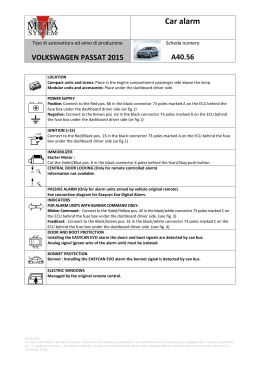
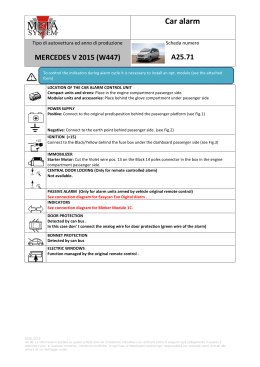
Car alarm
Tipo di autovettura ed anno di produzione
Scheda numero
MAZDA CX5 2012
A24.30
LOCATION
Compact units and sirens: Place on the driver side wheel cover on the original hole.
Centrali di comando e accessori: Place under the dashboard on driver side.
POWER SUPPLY
Positive: Connect to the White/Blue directly on the rear side of the fuse box behind the sill on driver side.
Negative: Connect to the original ground point on the driver side.
IGNITION (+15)
Connect to the Violet in the white connector placed in vertical position in the connector holder on the sill
on driver side (see Fig. 1)
IMMOBILIZER
Starter Motor :
Cut the Yellow/Black silver dots on the connector 2 poles on the clutch pedal.
CENTRAL DOOR LOCKING (Only for remote controller alarm)
Not available.
PASSIVE ALARM (Only for alarm units armed by vehicle original remote)
See connection diagram for Easy Can / Easy Can Evo Alarm.
INDICATORS
FOR ALARM UNITS WITH BLINKER COMMAND ONLY: set the function 10 in POWER .
Connect to the Blue/Red and Blue/Black on the white connector 50 poles in the connector holder on the sill on
driver side.
DOOR AND BOOT PROTECTION
Detected by can bus.
Analog signal (green wire of the alarm unit) must be isolated.
BONNET PROTECTION
Bonnet : Install the bonnet switch provided.
ELECTRIC WINDOWS
Function managed by the original remote control.
02/08/2012
rev.00Le informazioni riportate su questa scheda sono da considerarsi indicative e da verificarsi prima di eseguire ogni collegamento in quanto il costruttore
puo,’ in qualsiasi momento , introdurre modifiche. In ogni caso la MetaSystem declina ogni responsabilità per eventuali danni arrecati alla vettura da un
montaggio errato.
Car alarm
Tipo di autovettura ed anno di produzione
Scheda numero
MAZDA CX5 2012
A24.30
FITTING INSTRUCTIONS FOR EASY CAN / EASY CAN EVO DIGITAL ALARM
After completing connections, set the alarm unit for MAZDA 5 “61A” commands. (see LINKING UP THE
VEHICLE CAN in the fitting instruction for more details) by PDC programmer or PRG007
See previous diagram for other connection points.
See previous page for the rest of connection points.
Informations valid for cars equipped with the remote control as following:
Informations valid also for car equipped with Keyless entry system.
FUNCTION
ALARM WIRE
VEHICLE WIRE
CAN H
RED/BLACK
Green/grey dots
CAN L
VIOLET/BLACK
Violet/Grey dots
POSITION
Behind the EOBD
connector under the
dashboarddriver side (see
Fig. 2)
Fig. 1 + 15 Ignition
Fig. 2 Can Bus
02/08/2012
rev.00Le informazioni riportate su questa scheda sono da considerarsi indicative e da verificarsi prima di eseguire ogni collegamento in quanto il costruttore
puo,’ in qualsiasi momento , introdurre modifiche. In ogni caso la MetaSystem declina ogni responsabilità per eventuali danni arrecati alla vettura da un
montaggio errato.
Scarica