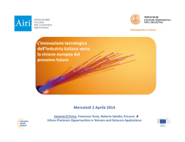
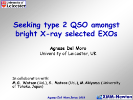
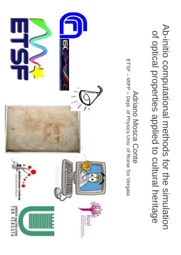
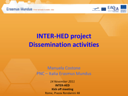
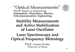
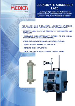
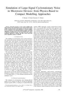
LIFT-THE ITALIAN LINK FOR TIME AND FREQUENCY F. Levi, D. Calonico, A. Mura, C.E. Calosso, M. Zucco INRIM, strada delle Cacce 91, Torino, Italy; C. Clivati, G. A. Costanzo, INRIM, strada delle Cacce 91, and Politecnico di Torino, Torino, Italy R. Ambrosini, Istituto di Radioastronomia, Bologna, Italy G. Galzerano, CNR IFN, Istituto di Fotonica e Nanotecnologie, Milano, Italy P. Denatale and D. Mazzotti CNR INO, Istituto Nazionale di Ottica, Firenze, Italy N. Poli and G. M. Tino Dip. di Fisica e Astronomia e LENS, Università di Firenze, INFN, sezione di Firenze, Sesto Fiorentino (FI), Italy We report on the realization of the coherent optical link for time and frequency dissemination that is being developed in Italy. The fiber backbone will connect scientific laboratories that need accurate time&frequency measurements located in Torino, Milano, Bologna and Firenze. We will describe the technique, and report the status of installation and preliminary characterization. Also, we highlight the possible applications this facility. 1. Introduction Optical frequency standards are recommended by the BIPM for the secondary representation of the second in the International System (SI) of units, and are the most promising candidates for its future redefinition [1]. However, atomic clocks are not transportable, so an adequate time&frequency (T&F) transfer technique is needed to perform remote standards comparisons and T&F dissemination. Optical fiber links can be used to this purpose [2,3] and their resolution exceeds the state-of-the-art satellite techniques by several orders of magnitude, provided that the phase noise introduced by the fiber due to mechanical stresses and temperature variations is compensated. This can be achieved by bidirectional Doppler cancellation [4]: thus, frequency dissemination at the 10-16 level of stability [2,3] and time dissemination at the 100 ps level [5] over distances of 1000 km can be obtained. The National Institute of Metrology (INRIM) realizes in Italy accurate T&F signals and disseminates them to a variety of scientific laboratories and industries. Presently, INRIM maintains two Cs primary frequency standards, with an accuracy at the 10-16 level [6], and is developing an optical clock based on Yb atoms [7]. To improve the quality of T&F dissemination, INRIM started together with other major National Institutions, the LIFT project (the Italian Link for Frequency and Time, funded within Progetti Premiali 2012), to realize an optical link along a 650 km fiber backbone that connects Torino to Milano, Bologna, and Firenze. The aim of the project is the distribution via optical fiber of the INRIM reference T&F signals with a target relative instability of 10-13 at 1 s measurement time and 10-18 at one day, to a variety of scientific laboratories, representing national centers of excellence in their fields. This facility will further improve their scientific capabilities, allowing these laboratories to better exploit existing experiments and to establish new ones in the future. Present partners of the project are the National Institute of Nuclear Physics in Firenze (INFN), in collaboration with LENS and Department of Physics and Astronomy of University of Firenze, the National Institute of Optics (INO) in Firenze; the National Institute of Astrophysics (INAF) in Medicina, near Bologna, and the National Council of Research (CNR) in Milano. Both INFN and CNR are involved in high resolution spectroscopic measurements, and will benefit from T&F dissemination via optical fiber. In particular, at LENS a Sr optical clock is under development [8], and its frequency comparison to the frequency standards of INRIM could allow a number of new fundamental physics experiments. INAF is involved in Very Long Baseline Interferometry (VLBI), and therefore needs ultrastable frequency references on long timescales. The quality of this reference signals will be improved thanks to direct optical fiber dissemination from INRIM. T&F measurements with improved resolution are expected to be performed from 2014, in the second stage of the project, whilst in the first start-up stage the fiber backbone will be fully characterized and preliminary tests and checks will be completed. 2. Coherent time and frequency dissemination through optical fiber A key point of the project is to use the same infrastructure to disseminate both time and frequency. When performing frequency dissemination, an ultrastable laser (1542 nm) is sent to the user, and its frequency is simultaneously measured in the two laboratories, with the aid of an optical frequency comb. The frequency of the delivered laser is perturbed by environmental noise in the fiber. However, it is possible to compensate this noise with an optoelectronic actuator; this technique requires that the end laboratory redirects the incoming signal to the start laboratory, where the delivered signal is compared with the received one, and the added noise is cancelled in real time. For the noise cancellation to be effective, there must be a fully-optical backbone with no optical/electrical conversions, and the light has to travel exactly the same fiber in both directions. This is quite different with respect to typical fiber transmission techniques, and poses several requirements on the optical instrumentation. To disseminate time signals, a pseudorandom noise will be encoded on the optical carrier, similarly to what is done in two way satellite time and frequency transfer: instead of cancelling the phase noise of the carrier itself, the measured transmission delay will be calibrated and stabilized, with a resolution exceeding 100 ps. The optical fiber used is a 650 km dedicated fiber, with a total attenuation of 200 dB. To partly compensate optical losses, we installed dedicated, fully bidirectional Erbium Doped Fiber Amplifiers along the path, that use the same active fiber in both directions [2-3]. 3. Link implementation and characterization One of the most demanding steps of the link implementation is to compensate the optical losses in such a bidirectional transmission scheme: the gain of our dedicated EDFAs could be set only with the whole operating link, as the gain and optical signal-to-noise ratio (OSNR) of each stage is affected by the others. Also, it has to stay below 20 dB, to prevent oscillation lasing effects and OSNR degradation due to backscattering and Amplified Spontaneous Emission [9]. Currently, 9 amplifiers have been installed, and optical filters have been used to keep the OSNR at an adequate level. One additional amplifier will be added in the next future. In Figure 1, the optical path is shown with the amplification shelters; the table reports for each station the distance from Torino and the optical losses of the span. Location Length Torino Santhia (VC) Novara (NO) Lainate (MI) Milano Piacenza Reggio Emilia Bologna Rioveggio (BO) Firenze LENS lab (FI) 22.5 km 89.8 km 166.6 km 216.4 km 277.2 km 344.5 km 438.7 km 513.0 km 550.8 km 622.7 km 640.3 km Losses 9 dB 18 dB 18 dB 15 dB 18 dB 16 dB 23 dB 19 dB 10 dB 18 dB 7 dB Figure 1: the map shows the optical path and amplification shelters, and the table shows the integrated length and the attenuation for each span. Measurements of the phase noise added by the fiber have been performed during EDFA installation on several amplification shelters, by reflecting back the signal towards INRIM. These measurements allowed us to check the noise contribution of each span and the phasecompensation capabilities of the control loop. Figure 2 shows the phase noise power spectral density of the correction signal applied to the actuator when the compensation loop was activated. It represents the phase noise of the fiber up to that intermediate station. 4 10 3 2 10 2 S(f) /rad /Hz 10 1 10 0 10 -1 10 Torino Santhia Novara Rogoredo -2 10 Piacenza Reggio Emilia Bologna -3 10 1 10 100 frequency /Hz Figure 2: phase noise of the fiber link starting at INRIM and ending at each specific station. Based on these measurements we estimated the achievable stability, in terms of Allan deviation in 1 kHz bandwidth, of the transferred signal at Milano, Bologna and Firenze, based on the assumption that the phase noise of the fiber scales with length and that the phase cancellation bandwidth is limited by the time it takes to the light to travel to the far fiber end and back [5], and thus decreases with the link length. -13 frequency instability (Allan deviation) 10 -14 10 Milano (277 km) Bologna (513 km) Firenze (650 km) -15 10 -16 10 -17 10 -18 10 1 10 100 1000 10000 averaging time /s Figure 3: estimated residual frequency instability of the compensated optical link at each user end, in terms of Allan deviation (1 kHz integration bandwidth). For an ultimate characterization, during next year, a second fiber link will be implemented in an antiparallel configuration [2]. This will allow to determine the contribution of the non-compensated phase noise of the fiber itself. Nevertheless, the present optical link can already be used for frequency dissemination to the reported sites. 4. Conclusions We report on the implementation and preliminary characterization of the 650 km fiber link connecting Torino to Milano, Bologna and Firenze within the LIFT project. At present, the fiber backbone has been implemented and preliminary characterization is being carried on. The amount of phase noise added by the optical fiber that cannot be compensated is not a limitation, and we estimated that frequency dissemination at the 10-16 level of stability in few minutes of averaging time can be obtained. Experiments related to time distribution will also performed in the next months. Fiber frequency dissemination represents a dramatic improvement with respect to satellite techniques, and enables frequency comparisons and calibrations at unprecedented levels of uncertainty, paving the way for a number of scientific experiments in the fields of high resolution spectroscopy, radioastronomy, fundamental physics. The development of this National network is of major interest also for high–tech industries, making available high quality T&F signals in real time, without the need of routine calibration. This infrastructure will be easily adapted to perform widespread dissemination towards a larger variety of users, with reduced costs. This secondary dissemination will use optical fiber as well, but instead of optical carrier it will distribute an amplitude modulated signal, much easier to detect and use. 5. Acknowledgments University of Florence, Politecnico of Turin and INRIM acknowledge the Italian Ministry of University (PRIN09-2009ZJJBLX) for funding the optical link. INRIM acknowledges for funding Compagnia di S. Paolo the EMRP program (Project SIB02-NEAT-FT), and the Italian Ministry of University (Progetti Premiali 2012). The EMRP is jointly funded by the EMRP participating countries within EURAMET and the European Union. INRIM acknowledges GARR for the technical help with the fiber. Bibliography [1] C. W. Chou, D. B. Hume, J. C. J. Koelemeij, D. J. Wineland, and T. Rosenband, “Frequency Comparison of Two High-Accuracy Al+ Optical Clocks,” Phys. Rev. Lett. 104, 070802 (2010). [2] O. Lopez, A. Haboucha, F. Kefelian, H. Jiang, B. Chanteau, V. Roncin, C. Chardonnet, A. AmyKlein, G. Santarelli, “Cascaded multiplexed optical link on a telecommunication network for frequency dissemination,” Opt. Expr. 18, 16849-16857 (2010). [3] K. Predehl, G. Grosche, S. M. F. Raupach, S. Droste, O. Terra, J. Alnis, Th. Legero,T. W. Hansch, Th. Udem, R. Holzwarth, H. Schnatz, “A 920-Kilometer Optical Fiber Link for Frequency Metrology at the 19th decimal place,” Science 336, 441-444 (2012). [4] W. Williams, W. C. Swann, and N. R. Newbury, “High-stability transfer of an optical frequency over long fiber optic links,” J. Opt. Soc. Am. B 25, 1284-1293 (2008). [5] O. Lopez, A. Kanj, P. Pottie, D. Rovera, J. Achkar, C. Chardonnet, A. Amy-Klein, G. Santarelli "Simultaneous remote transfer of accurate timing and optical frequency over a public fiber network" Appl. Phys. B 110, 3–6 (2013). [6] F. Levi, C. calosso, D. Calonico, L. Lorini, E. K. Bertacco, A. Godone, G. A. Costanzo, B. Mongino, S. Jefferts, T. P. Heavner, E. A. Donley “Cryogenic Fountain Development at NIST and INRIM: Preliminary Characterization”, IEEE Trans. Ultrason. Ferroelectr. Freq. Contr. 57, 600-605, (2010) [7] M. Pizzocaro, G. A. Costanzo, A. Godone, F. Levi, A. Mura, M. Zoppi, D. Calonico, “Realization of an Ultrastable 578 nm Laser for an Yb Lattice Clock”, IEEE Trans. Ultrason. Ferroelectr. Freq. Contr. 59, 3, 426431 (2012). [8] N. Poli, M. G. Tarallo, M. Schioppo, C. W. Oates and G. M. Tino "A simplified optical lattice clock", Appl. Phys. B 97, 27-33 (2009). [9] L. Sliwczynski and J. Kolodziej, “Bidirectional Optical Amplification in Long-Distance Two-Way Fiber-Optic Time and Frequency Transfer Systems”, IEEE Trans. Instrum. Meas. 62, 1, 2013.
Scarica