Il modulo Z202 misura il valore della tensione alternata applicata ai morsetti di
ingresso, convertendolo in un segnale normalizzato in corrente e in tensione ai morsetti
d'uscita.
Lo strumento si distingue per la classe di precisione e l'elevata impedenza d'ingresso;
le caratteristiche generali di cui gode sono le seguenti:
Lo strumento sopporta un sovraccarico del 200 % per 10 s; sovraccarichi superiori o
prolungati possono causare danneggiamento o staratura della sezione d'ingresso dello
strumento stesso; si consiglia pertanto di verificare con attenzione le impostazioni
prima di applicare la tensione di misura, eventualmente misurando con un ohmmetro la
resistenza di ingresso che deve essere pari a Rin = 2 000 W·Portata (V).
Portata
490 V (F)
480 V
470 V
460 V
440 V
430 V
420 V
410 V
390 V
380 V
370 V
360 V
350 V
340 V
320 V
310 V
300 V
290 V
270 V
260 V
250 V
SPECIFICHE TECNICHE
9..40 VDC (polarità libera) o 19..28 VAC 50..400 Hz; il modulo è
stato espressamente disegnato per poter funzionare anche
con accumulatori a 12 V.
Isolamento verso i morsetti d'uscita: 1500 V. Protezione 400
W/ms.
<1.5 W a pieno carico; circa 60mA @ 12Vdc senza carico.
Ingresso Tensione:
Tensione alternata 0..500 Vac; si veda la tabella per la
selezione della portata.
Impedenza ingresso: 2000 W/V.
Frequenza: 10 Hz..1 kHz.
Isolamento verso i morsetti di alimentazione/uscita: 3750 V.
(1)
MI000910-I/E
Attiva o passiva: 0..20 mA o 4..20 mA selezionabile tramite
DIP-switch(2).
Resistenza massima di carico : 600 W. Protezione 400
W/ms.
Uscita Corrente:
CMR
@ 25ºC:
35..400 Hz
(4)
10 Hz..1 kHz
(4)
Altro
INGOMBRI
(1)
0.2 %dm
0.05 %ds
>60 dB
0.02% d.s.
0.3 %dm
0.15 %ds
>55 dB
0.02% d.s.
Stabilità Termica:
100 ppm/K.
Tempo di Risposta:
Per una variazione a gradino: 30 ms dal 10 al 90 %.
Condizioni Ambientali: Temperatura: 0..60°C, umidità 30÷90 % @ 40°C non
condensante.
Segnalazioni a LED:
Alimentazione presente (verde).
Grado di protezione:
IP20.
Peso, Dimensioni:
140 g, 100 x 112 x 17.5 mm.
EN50081-2 (emissione elettromagnetica, ambiente
industriale)
EN50082-2 (immunità elettromagnetica, ambiente industriale)
EN61010-1 (sicurezza)
Tutti i circuiti devono essere isolati con doppio isolamento dai
circuiti sotto tensione pericolosa. Il trasformatore di
alimentazione deve essere a norma EN60742: “Trasformatori
di isolamento e trasformatori di sicurezza”.
SW3
1000
1000
1001
1011
1000
1000
1001
1011
1100
1100
1000
1001
1011
1011
1100
1100
1101
1111
1100
1101
1101
Portata
240 V
230 V
220 V
200 V
190 V
180 V
170 V
150 V
140 V
130 V
120 V
110 V
100 V
80 V
70 V
60 V
50 V
30 V
20 V
10 V
0 V (I)
Morsetti
9 (N), 11
8 (N), 11
8 (N), 11
8 (N), 11
8 (N), 11
8 (N), 11
8 (N), 11
8 (N), 11
8 (N), 11
8 (N), 10
8 (N), 10
8 (N), 10
8 (N), 10
8 (N), 10
8 (N), 10
8 (N), 10
8 (N), 10
8, 10
8, 10
8, 10
8, 10
MI000910-I/E
SW2
11
01
01
10
11
11
11
10
11
00
00
00
01
00
01
01
01
10
10
10
11
SW3
1111
1001
1011
1000
1000
1001
1011
1100
1100
1000
1001
1011
1011
1100
1100
1101
1111
1100
1101
1111
1111
9..40 VDC
19..28 VAC
La tensione di alimentazione deve essere compresa tra
9..40 VDC (polarità indifferente), 19..28 VAC; vedere anche la
sezione NORME DI INSTALLAZIONE.
I Iimiti superiori non devono essere superati, pena
gravi danni al modulo.
E' necessario proteggere la sorgente di alimentazione da
eventuali guasti del modulo mediante fusibile
opportunamente dimensionato.
2 3
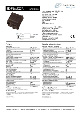
COLLEGAMENTO TENSIONE ALTERNATA DI INGRESSO
10
V
FONDO-SCALA 10 .. 130 Vac
(N)
8
11
V
FONDO-SCALA 140 .. 230 Vac
(N)
8
11
V
FONDO-SCALA 240 .. 370 Vac
(N)
9
12
V
FONDO-SCALA 380 .. 490 Vac
(N)
9
10
uA
MICRO-AMPEROMETRO
8
ITALIANO - 5/8
MI000910-I/E
(N): Nel caso in cui uno dei due fili sia il neutro o la terra, collegarlo preferibilmente al
morsetto indicato.
(I) : Utile quando si voglia usare lo strumento come microamperometro (500 µA fs) o
per portate inferiori ai 10 V (SW3.1 aperto).
(F): Configurazione di fabbrica.
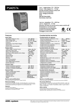
REGOLAZIONE DEL FONDO-SCALA
Portando in posizione “0” (OFF) lo switch SW3.1, si introduce l'effetto di regolazione del
trimmer accessibile dal frontale, il che consente di ampliare ogni scala fissa di un valore
compreso tra 0 V (0 W completamente antiorario) e 25 V (50 kW completamente orario);
la resistenza del trimmer è accessibile ai morsetti 7 e 8: è posssibile pertanto
conoscere di quanti Volt è stata ampliata la scala, misurando con un ohmmetro questa
resistenza e dividendone il valore per 2000 W/V.
È anche possibile “tarare” lo strumento applicando la tensione nota ai morsetti di
ingresso (come da tabella) e regolando il trimmer fino ad ottenere la lettura desiderata;
quando la tensione applicata sia superiore a 42 V è obbligatorio fare uso di un
cacciavite isolato, non essendo garantito l'isolamento della vite di regolazione.
Si rimanda agli esempi del prossimo paragrafo.
Il fondo-scala può essere incrementato di un valore
compreso tra 0 V e 25 V rispetto al valore nominale del
fondo-scala impostato.
La misura in ohm divisa per 2.000 fornisce il valore da
aggiungere al fondo-scala.
Esempio: se si legge 30.000 ohm, il valore del fondo-scala
viene incrementato di 30.000 / 2.000 = 15 V
ATTENZIONE!
OPERAZIONE DA EFFETTUARE CON
STRUMENTO NON ALIMENTATO E INGRESSO
SCOLLEGATO.
ITALIANO - 7/8
ohm
8
7
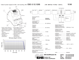
COLLEGAMENTO USCITE
Categ. d’installazione: III, per installazione su rete trifase fino a 500 Vac f-f, 300 Vac
f-n.
Normative di
Conformità:
SW2
00
01
01
01
10
11
11
11
10
11
00
00
00
01
00
01
01
01
10
10
11
ITALIANO - 3/8
112 mm
(3)
MI000910-I/E
Tensione continua: 0..5 V, 1..5 V, 0..10 V o 2..10V
(2)
selezionabile tramite DIP-switch .
Resistenza minima di carico : 2500 W. Protezione 400 W/ms.
Uscita Tensione:
Precisione
ITALIANO - 1/8
Morsetti
9 (N), 12
9 (N), 12
9 (N), 12
9 (N), 12
9 (N), 12
9 (N), 12
9 (N), 12
9 (N), 12
9 (N), 12
9 (N), 12
9 (N), 11
9 (N), 11
9 (N), 11
9 (N), 11
9 (N), 11
9 (N), 11
9 (N), 11
9 (N), 11
9 (N), 11
9 (N), 11
9 (N), 11
ALIMENTAZIONE
17,5 mm
PREDISPOSIZIONE DEL SEGNALE DI USCITA
4
Lo strumento Z202 trasmette contemporaneamente un segnale di tensione ed uno di
corrente. Le scale dei segnali sono impostabili mediante il dip-switch doppio SW1; in
paticolare:
5
Switch 1 Posizione
0 - OFF
SW 1.1
1 - ON (F)
0 - OFF
SW 1.2
1 - ON (F)
(F)
Effetto
Il fondo-scala per l’uscita in tensione è 5 V
Il fondo-scala per l’uscita in tensione è 10 V
L'offset di inizio scala è disabilitato (scale 0..20 mA, 0..5/10 V)
L'offset di inizio scala è abilitato (scale 4..20 mA, 1..5 o 2..10 V)
: Configurazione di fabbrica
CORRENTE (COLLEGAMENTO ATTIVO)
mA
mA
5
+
Consumo:
ATTENZIONE!
PRIMA DI EFFETTUARE QUALSIASI COLLEGAMENTO ALLO
STRUMENTO ACCERTARSI DI AVERE DISCONNESSO TUTTI I CIRCUITI
A TENSIONI PERICOLOSE.
La portata dello strumento è stabilita dall'impostazione dei DIP-switch SW2 (2 vie) e
SW3 (4 vie) unitamente alla scelta dei morsetti d'ingresso; la tabella sottostante riporta
le combinazioni utili per le portate pretarate.
Lo stato dei DIP-switch è rappresentato da una serie di “1” e “0”, che, nell'ordine,
indicano rispettivamente “ON” (verso il frontale dello strumento) e “OFF” (verso il fondo
dello strumento).
Ingresso in tensione alternata 10..490 Vac in 41 scale pre-tarate, selezionabili a
mezzo morsetti/DIP-switch.
Possibilità di tarare ed estendere ogni scala a quella successiva, consentendo la
calibrazione in un qualsiasi fondo scala nel range continuo 0..500 Vac, senza né
starare le portate fisse, né aprire lo strumento (trimmer multigiri accessibile dal
frontalino).
Uscita contemporanea in corrente (0/4..20 mA attiva/passiva) ed in tensione (0/1..5 V
o 0/2..10 V).
Elevata precisione e linearità: 0,25%.
Range esteso della frequenza d'ingresso (10 Hz..1 kHz).
Tempo di assestamento estremamente breve (<30 ms).
Isolamento galvanico tra l'ingresso di tensione e gli altri morsetti pari a 3750 V.
Isolamento tra i morsetti di uscita e quelli di alimentazione di 1500 V.
Indicazione della presenza di alimentazione a mezzo di LED a pannello.
Possibilità di utilizzare lo strumento come microamperometro (500 µAfs R=5 W).
Ampio range di alimentazione AC/DC, compreso il funzionamento con accumulatori a
12 V.
Alimentazione:
COLLEGAMENTI ELETTRICI
ATTENZIONE!
PRIMA DI MANOVRARE I DIP-SWITCH ACCERTARSI DI AVERE
DISCONNESSO TUTTI I CIRCUITI A TENSIONI PERICOLOSE.
+
CARATTERISTICHE GENERALI
PREDISPOSIZIONE PORTATA INGRESSO
+
Z202
NORME DI INSTALLAZIONE
Il modulo è progettato per essere montato su guida DIN 46277 e cablato unicamente a
mezzo dei morsetti frontali. Al fine di favorire la ventilazione del modulo stesso, ne viene
consigliato il montaggio in posizione verticale, evitando di posizionare canaline o altri
oggetti che ne occludano le feritoie di aereazione.
Evitare di collocare il modulo sopra apparecchiature che generino calore; è consigliabile la
collocazione nella parte bassa del quadro o del vano di contenimento.
6
CORRENTE (COLLEGAMENTO PASSIVO)
Vext
1
+
CONVERTITORE PER TENSIONE ALTERNATA
I
TENSIONE
V
1
100 mm
Note:
(1): È tollerato un valore medio della tensione (Vcc) fino al 10 %dm; valori superiori degradano la
precisione e possono recare danni.
(2): La selezione dell'offset di inizio scala (4 mA e 1 o 2 V) è comune alle due uscite
corrente/tensione.
(3): Valgono gli acronimi: dm = della misura, ds = della scala.
(4): Le precisioni sono indicate per un segnale sinusoidale con distorsione <1 %, sulla lettura in
corrente 4..20 mA; gli errori sulle altre scale di uscita vanno così aumentati: dello 0.05% quando
non vi sia offset di zero (4 mA, 1 o 2 V), dello 0.17% sul fs 5 V e dello 0.1% sul fs 10 V. A
richiesta è possibile avere la precisione indicata in tabella su di un'altra scala specificata.
Si rammenta che lo strumento riporta il valore medio rettificato rapportato al valore efficace.
ESEMPI CONFIGURAZIONE MODULO
Vengono di seguito riportati due esempi di configurazione:
Morsetti INGRESSO
SW1
SW2
SW3
- Tensione di INGRESSO 250 Vac
- Uscite 4..20 mA e 1..5 V
9 (N) - 11
0-1
1-1
1-1-0-1
- Tensione di INGRESSO 120 V
- Uscite 0..20 mA e 0..10 V
8 (N) - 10
1-0
0-0
1-0-0-1
Questo documento è di proprietà SENECA srl. La duplicazione e la riproduzione sono vietate, se non
autorizzate. Il contenuto della presente documentazione corrisponde ai prodotti e alle tecnologie
descritte. I dati riportati potranno essere modificati o integrati per esigenze tecniche e/o commerciali. Il
contenuto della presente
R
THE INTERNATIONAL CERTIFICATION NETWORK
ISO9001-2000
MI000910-I/E
ITALIANO - 2/8
MI000910-I/E
ITALIANO - 4/8
MI000910-I/E
ITALIANO - 6/8
MI000910-I/E
ITALIANO - 8/8
INSTALLATION
ALTERNATE VOLTAGE CONVERTER
Z202
GENERAL FEATURES
The Z202 module measures the alternate voltage input value and converts it into a
current or voltage signals output.
The instrument stands out for its precision class and its high input impedance. These
are its general features:
INPUT FULL-SCALE PRE-SETTING
The module is designed to be installed on a DIN 46277 guide, and wired only by front
terminals.
We suggest you to install the instrument vertically in order to arrange the ventilation of
the module and pay attention to do not fit any objects or canals that can obstruct its
ventilation louvers.
Avoid fitting modules above equipment that generates heat; you are advised to fit them
at the bottom of the panel or on the enclosing compartment.
Full-scale Terminals SW2
490 V (F) 9 (N), 12
00
01
480 V
9 (N), 12
9 (N), 12
470 V
01
460 V
9 (N), 12
01
10
440 V
9 (N), 12
9 (N), 12
430 V
11
420 V
9 (N), 12
11
410 V
9 (N), 12
11
390 V
9 (N), 12
10
380 V
11
9 (N), 12
370 V
9 (N), 11
00
360 V
9 (N), 11
00
9 (N), 11
350 V
00
340 V
9 (N), 11
01
320 V
00
9 (N), 11
310 V
9 (N), 11
01
300 V
01
9 (N), 11
290 V
01
9 (N), 11
270 V
9 (N), 11
10
260 V
10
9 (N), 11
250 V
9 (N), 11
11
TECHNICAL FEATURES
9..40 VDC (free polarity) or 19..28 VAC 50..400 Hz. The module
was specifically designed to operate also on 12 V batteries.
Insulation toward the output terminals: 1500 V. Protection
400 W/ms.
Consumption:
<1.5 W at full load; about 60mA @ 12Vdc.
Voltage input:
Alternate voltage 0..500 Vac; see the capacity selection
table.
Input impedance: 2000 W/V.
Frequency: 10 Hz..1 kHz.
Insulation toward the power supply/output terminals: 3750 V.
(1)
Active or passive 0..20 mA or 4..20 mA setup via DIPswitchs(2).
Maximum load resistance: 600 ohm. Protection 400 W/ms.
ENGLISH - 3/8
OVERALL DIMENSIONS
Continuous voltage:
(2)
0..5 V, 1..5 V, 0..10 V or 2..10V selected by DIP-switch .
Minimum load resistance: 2500 ohm. Protection 400 W/ms.
(4)
10 Hz..1 kHz
(4)
CMR
Others
(1)
0.2 %om
0.05 %ots
>60 dB
0.02% o.s.
0.3 %om
0.15 %ots
>55 dB
0.02% o.s.
Thermal stability:
100 ppm/K.
Response time:
For a stepped variation: 30 ms from 10 to 90%.
Operating
temperature:
Temperature: 0..60°C , Max humidity 30..90% at 40°C noncondensing.
LED signals:
Power ON (green).
Protection:
IP20.
Weight, dimensions:
140 g, 100 x 112 x 17.5 mm.
Installation class:
III, for installation on 3-phase lines up to 500 Vac f-f, 300 Vac
f-n.
MI000910-I/E
SW3
1111
1001
1011
1000
1000
1001
1011
1100
1100
1000
1001
1011
1011
1100
1100
1101
1111
1100
1101
1111
1111
9..40 VDC Power supply voltage must be in the range 9..40 VDC (at any
19..28 VAC polarity), 19..28 VAC; also see section; INSTALLATION
INSTRUCTIONS.
The upper limits must not be exceeded, to avoid
serious damage to the module.
Protect the power supply source against possible
damage of the module by using a fuse of suitable size.
2 3
CONNECTION OF ALTERNATE INPUT VOLTAGE
10
FULL-SCALE 10 .. 130 Vac
V
(N)
8
11
FULL-SCALE 140 .. 230 Vac
V
(N)
8
11
FULL-SCALE 240 .. 370 Vac
V
(N)
9
12
FULL-SCALE 380 .. 490 Vac
V
(N)
9
10
uA
MICRO-AMMETER
8
ENGLISH - 5/8
MI000910-I/E
(N): If one of the two wires is neutral or earth, connect it preferably to the indicated
terminal.
(I) : This is useful if you wish to use the instrument as a microammeter (500 µA fs) or
for range values below 10 V (SW3.1 open).
(F): Factory configuration.
ADJUST OF FULL-SCALE
If you turn OFF ("0" position) switch SW3.1, this introduces the adjustment effect of the
trimmer, accessible from the front panel. This enables you to broaden each fixed scale
by a value between 0 V (0 W completely ccw) and 25 V (50 kW completely cw). The
trimmer resistance can be accessed on terminals 7 and 8. In this way you can find out
by how many volts the scale was increased, by measuring this resistance with an
ohmmeter and dividing the value by 2000 W/V.
The instrument can also be 'set' by applying the known voltage on the input terminals
(as on the table) and adjusting the trimmer until you obtain the required reading. When
the applied voltage exceeds 42 V, you must use an insulated screwdriver, because the
insulation of the adjusting screws is not guaranteed.
See the examples in the next paragraph.
The full-scale can be increased by a value from 0 V to 25 V
with respect to the rated value of the set full-scale.
The measurement in ohms divided by 2,000 provides the
value to be added to the full-scale.
Example: if the reading is 30,000 ohm, the full-scale value is
increased by 30,000 / 2,.000 = 15 V
CAUTION!
THIS OPERATION MUST BE CARRIED OUT
WITH POWER CUT TO THE INSTRUMENT AND
WITH THE INPUT DISCONNECTED.
ENGLISH - 7/8
ohm
8
7
CONNECTION OF OUTPUTS
OUTPUT SIGNAL PRE-SETTING
EN50081-2 (electromagnetic emission, industrial environment)
EN50082-2 (electromagnetic immunity, industrial environment)
EN61010-1 (safety)
All the circuits must be provided with double isolation against
circuits under dangerous voltage. The power supply
transformer must comply with EN60742 standards for
isolation transformers and safety transformers. The power
supply transformer must comply with EN60742 standards for
insulation transformers and safety transformers. " Insulation
transformers and safety transformers".
The Z202 instrument simultaneously transmits a voltage and a current signal. The
signal scales can be set with the double dip-switch SW1; specifically:
17,5 mm
Switch 1 Position
0 - OFF
SW 1.1
1 - ON (F)
0 - OFF
SW 1.2
1 - ON (F)
Effect
The full scale of the voltage output is 5 V
The full scale of the voltage output is 10 V
The start of scale offset is disabled (scale 0..20 mA, 0..5/10 V)
The start of scale offset is enabled (scale 4..20mA, 1..5 or
2..10V)
(F) : Factory configuration
4
CURRENT (ACTIVE CONNECTION)
mA
5
mA
5
+
Precision (3) @ 25ºC:
112 mm
Voltage output:
Conform to CE
standards:
MI000910-I/E
Full-scale Terminals SW2
240 V
9 (N), 11
11
230 V
01
8 (N), 11
220 V
8 (N), 11
01
200 V
10
8 (N), 11
190 V
11
8 (N), 11
180 V
8 (N), 11
11
170 V
11
8 (N), 11
150 V
8 (N), 11
10
140 V
11
8 (N), 11
130 V
00
8 (N), 10
120 V
8 (N), 10
00
110 V
00
8 (N), 10
100 V
8 (N), 10
01
80 V
00
8 (N), 10
70 V
01
8 (N), 10
60 V
01
8 (N), 10
50 V
01
8 (N), 10
30 V
10
8, 10
20 V
10
8, 10
10 V
10
8, 10
0 V (I)
11
8, 10
POWER SUPPLY
+
Current output:
35..400 Hz
ENGLISH - 1/8
SW3
1000
1000
1001
1011
1000
1000
1001
1011
1100
1100
1000
1001
1011
1011
1100
1100
1101
1111
1100
1101
1101
CAUTION!
BEFORE MAKING ANY CONNECTION TO THE INSTRUMENT, MAKE
SURE THAT YOU HAVE DISCONNECTED ALL CIRCUITS AT
DANGEROUS VOLTAGE.
+
MI000910-I/E
The instrument withstands an overload of 200% for 10 s. Higher or prolonged overload
values may damage instrument's input section. We therefore advise you to carefully
check the settings before applying the measurement voltage, if necessary using an
ohmmeter to measure the input resistance which should be Rin = 2 000 W· Range (V).
The range of the instrument is established by the positions of the DIP-switches SW2 (2
way) and SW3 (4 way) and by the choice of the input terminals. The table below shows
the combinations useful for the preset capacity values.
The status of the DIP-switches is indicated by a series of “1” and “0”, which, in that
order respectively indicate "ON" (toward the front of the instrument) and "OFF" (toward
the rear of the instrument).
Alternate voltage input 10..490 Vac in 41 preset scales, which can be selected by
terminals/Dipswitches.
Each scale can be set and extended to the next one, and it's possible to calibrate the
instrument on any full-scale in the continuous range of 0…500 Vac, without either
over-setting the fixed capacities, or opening the instrument (multi-rev trimmer
accessible from front panel).
Simultaneous output in current (0/4..20 mA active/passive) and in voltage (0/1..5 V or
0/2..10 V).
High precision and linearity: 0.25%.
Wide range of frequency input (10 Hz..1 kHz).
Extremely short settling time (<30 ms).
3750 V galvanic isolation between voltage input and the other terminals.
1500 V isolation between the output terminals and the power supply terminals.
Power ON indication by the panel LED.
Possibility to use the instrument as a microammeter (500 µAfs R=5 W).
Wide range of power supply AC/DC , including operation on 12 V batteries.
Power supply:
ELECTRICAL CONNECTIONS
CAUTION!
BEFORE YOU ATTEMPT USING THE DIP-SWITCHES, MAKE SURE
THAT YOU HAVE DISCONNECTED ALL CIRCUITS AT DANGEROUS
VOLTAGE.
6
VOLTAGE
V
100 mm
1
EXAMPLES OF POSSIBLE CONFIGURATIONS
Note:
(1): A medium voltage value (Vcc) up to 10% dm is tolerated; higher values decrease precision
and can cause damages.
(2): The selection of starting offset scale (4 mA and 1 or 2V) is common for the two
current/voltage outputs.
(3): These acronyms apply: om = of measurement, ots = of the scale.
(4): The precision values are indicated for a sinusoidal signal with distortion of <1%, on current
reading 4..20 mA; errors on the other output scales are increased as follows: by 0.05% for zero
offset (0 mA, 0 V), by 0.17% on fs 5 V and by 0.1% on fs 10 V.
The precision indicated in the table can, on request, be provided on another specified scale.
Remember that the instrument indicates the average adjusted value in relation to the RMS value.
CURRENT (PASSIVE CONNECTION)
Vext
1
+
EN
Here are two examples of possible configurations:
Terminals
SW1
SW2
SW3
- INPUT Voltage 250 Vac
- Outputs 4..20 mA and 1..5 V
9 (N) - 11
0-1
1-1
1-1-0-1
- INPUT Voltage 120 V
- Outputs 0..20 mA and 0..10 V
8 (N) - 10
1-0
0-0
1-0-0-1
This document is property of SENECA srl. Duplication and reprodution are forbidden, if not authorized.
Contents of the present documentation refers to products and technologies described in it. All technical
data contained in the document may be modified without prior notice Content of this documentation is
subject to periodical revision.
R
THE INTERNATIONAL CERTIFICATION NETWORK
ISO9001-2000
MI000910-I/E
ENGLISH - 2/8
MI000910-I/E
ENGLISH - 4/8
MI000910-I/E
ENGLISH - 6/8
MI000910-I/E
ENGLISH - 8/8
Scarica