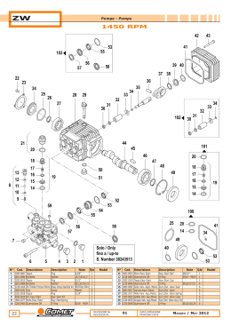
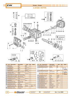
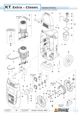
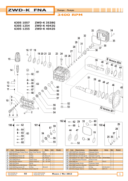
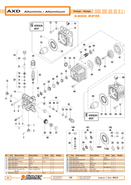
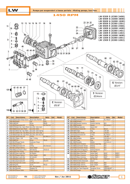
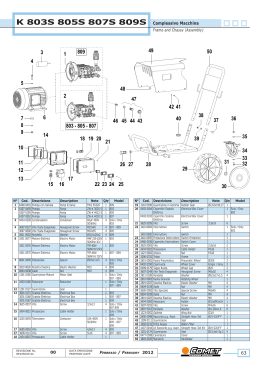
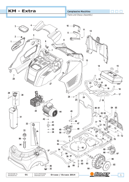
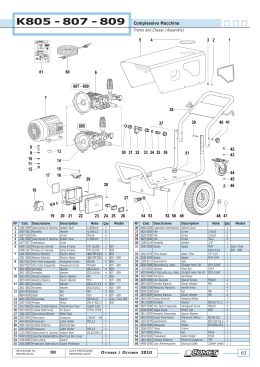
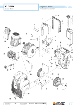
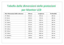
MTP ZW-K
Motopompe - Motorpumps
1400 RPM
1
2
N°
Cod.
1 6307 0455
6307 0352
6307 0157
2 1831 0513
1831 0543
Descrizione
Description
Pompa
Pompa
Pompa
Motore Elettrico
Motore Elettrico
Pump
Pump
Pump
Electric Motor
Electric Motor
REVISIONE Nr.
REVISION Nr.
00
Note
Q.ty
Model
ZW-K 3020S
ZW-K 3525S
ZW-K 4022S
MNF 3CV
TRF 5,5CV
1
1
1
1
1
5.11TS
5.13TS
5.15TS
5.11TS
5.13TS - 5.15TS
DATA EMISSIONE
PRINTING DATE
Gennaio / January 2013
1
MTP ZW-K
Pompe - Pumps
1400 RPM
ZW-K 3020 (6307 0455)
ZW-K 3525 (6307 0352)
ZW-K 4022 (6307 0157)
52
53
51
49 50
32
47 48
33
34
35
36
38
39
37
40
41
42
43
44
29
45
103
54
31
46
55
56
30
28
60
27
26
25
24
61
71
68
23
22
21
20
67
19
8
12
15 14
11
66
65
7
10
13
63
64
2
3
4
5
6
18
17
57
58
59
62
102
40
41
1
35
30
24
42
43
51
30
44
59
29
50
9
63
REVISIONE Nr.
REVISION Nr.
00
DATA EMISSIONE
PRINTING DATE
44
101
100
16
2
66
63
69
70
72
74
73
67
65
62
Gennaio / January 2013
MTP ZW-K
Pompe - Pumps
1400 RPM
N°
Cod.
1
2
3
4
5
6
7
8
5033 0010
3202 0319
1210 0463
3003 0033
1210 0463
1802 0277
2421 0037
3218 0426
Descrizione
Q.ty
Model
1
1
Ø2x6 - 90SH 1
Ø9/32”
1
Ø2x6 - 90SH 1
1
G1/8 25 bar 1
Ø18 - Easy
1 3.11TS - 5.13TS
Start
Ø18 - Easy
1 5.15TS
Start
M/M G1/2”1
3/4”
10 1210 0460 Guarnizione OR
O-Ring
Ø2,4x4,3
1
11 2409 0122 Pistone NON Ritorno
Check Valve
1
12 1802 0197 Molla
Spring
1
13 2409 0123 Ki Pistone NON Ritorno Check Valve Kit
1
14 1210 0402 Guarnizione OR
O-Ring
1
15 1210 0398 Guarnizione OR
O-Ring
1
16 3410 0289 Kit Eiettore
Injector Body Kit
Ø1,8 1 3.11TS - 5.13TS
M22x1,5
3410 0324 Kit Eiettore
Injector Body Kit
Ø2,1 1 5.15TS
M22x1,5
17 3609 0191 Vite
Screw
M8x60
8
18 3202 0018 Tappo
Plug
G1/8”
1
19 1816 0136 Manometro
Gauge
Ø50 0-30MPa 1
G1/8”
20 2811 0086 Rondella
Washer
Ø21,2x27x1,5 1
21 3202 0015 Tappo
Plug
G1/2”
1
22 2811 0084 Rondella
Washer
Ø16,7x22x1,5 1
23 3200 0007 Tappo
Plug
G3/8”
1
24 1210 0046 Guarnizione OR
O-Ring
Ø2,62x17,13 6
25 3009 0087 Sede Valv. Aspir./Mand. Suct./Del. Valve Seat
6
26 3604 0017 Valvola Aspir./Mand.
Suct./Del. Valve
6
27 1802 0177 Molla Valv. Asp./Mand. Suct./Del. Valve Spring
6
28 1205 0025 Gabbia Valv. Asp./
Suct./Del. Valve Cage
6
Mand.
29 1220 0030 Gruppo Valv. Asp./
Suct./Del. Valve
6
Mand.
Ass.y kit
30 1210 0048 Guarnizione OR
O-Ring
Ø2,62x20,24 6
31 3202 0312 Kit Tappo
Cap Kit
6
32 3609 0088 Vite
Screw
M5x10
3
33 1004 0012 Flangia Tenuta
Crankcase Flange
1
34 0402 0360 Coperchio
Cover
1
35 1210 0386 Guarnizione OR
O-Ring
Ø3,53x44,04 1
36 3019 0011 Seeger Esterno
Outer Seeger
1
37 0438 0066 Cuscinetto a Sfere
Ball Bearing
Ø20x52x15
1 3.11TS
0438 0069 Cuscinetto a Sfere
Ball Bearing
Ø20x52x15
1 5.13TS - 5.15TS
38 0403 0141 Carter Pompa
Pump Crankcase
1
39 3200 0051 Asta Livello Olio
Oil Dipstick
1
40 0600 0048 Dado Speciale
Special Bolt
3
41 2811 0080 Rondella
Washer
Ø8,2x14x1,5 3
42 0202 0018 Bussola Ceramica
Ceramic Bushing
Ø18
3 3.11TS - 5.13TS
0202 0040 Bussola Ceramica
Ceramic Bushing
Ø18
3 5.15TS
43 2812 0038 Rondella
Washer
3
44 1210 0055 Guarnizione OR
O-Ring
Ø1,78x6,07
3 3.11TS - 5.13TS
1210 0227 Guarnizione OR
O-Ring
Ø1,78x5,28
3 5.15TS
45 2409 0044 Pistone Guida
Piston Guides
3 3.11TS - 5.13TS
2409 0105 Pistone Guida
Piston Guides
3 5.15TS
46 3011 0014 Spinotto
Gudgeon Pin
Ø8x25
3
47 0205 0048 Kit Biella
Con. Rod Assembly
3 3.11TS
0205 0050 Kit Biella
Con. Rod Assembly
3 5.13TS - 5.15TS
48 3019 0033 Seeger Esterno
Outer Seeger
Ø28
1
49 3201 0026 Spia Livello Olio
Oil Indicator
1
50 1210 0451 Guarnizione OR
O-Ring
Ø2x24
1
51 1210 0621 Guarnizione OR
O-Ring
Ø3x94
1
52 0402 0142 Coperchio Carter
Crankcase Cover
1
53 3609 0041 Vite
Screw
M6x25
4
54 0001 0401 Albero Passante
Throughshaft
Ø24
1 3.11TS
0001 0294 Albero Passante
Throughshaft
Ø24
1 5.13TS
0001 0473 Albero Passante
Throughshaft
Ø24
1 5.15TS
55 1602 0045 Linguetta
Key
8x7x25
1
56 0438 0075 Cuscinetto a Sfere
Ball Bearing
Ø25x62x17
1 3.11TS
0438 0071 Cuscinetto a Sfere
Ball Bearing
Ø25x62x17
1 5.13TS - 5.15TS
57 3019 0006 Seeger Esterno
Outer Seeger
Ø25
1
58 3020 0012 Seeger Interno
Inner Seeger
Ø62
1
Kit Easy Start
Tappo Easy Start
Guarnizione OR
Sfera Easy Start
Guarnizione OR
Molla Easy Start
Pressostato
Kit Testata Pompa
Ottone + Easy Start
3218 0386 Kit Testata Pompa
Ottone + Easy Start
9 2000 0127 Nipplo
REVISIONE Nr.
REVISION Nr.
00
Description
Note
Easy Start Kit
Easy Start Cap
O-Ring
Easy Start Ball
O-Ring
Easy StartSpring
Pressure Switch
Brass Pump Manifold
Kit + Easy Start
Brass Pump Manifold
Kit + Easy Start
Nipple
DATA EMISSIONE
PRINTING DATE
N°
Cod.
59
60
61
62
63
64
0019 0094
1210 0441
3200 0007
0019 0095
1210 0223
0009 0197
0009 0368
1241 0028
1241 0022
0009 0193
1215 0584
1215 0585
1817 0054
2421 0037
2803 0424
3003 0026
1802 0180
2803 0435
65
66
67
68
69
70
71
72
73
74
Descrizione
Description
Anello Tenuta
Guarnizione OR
Tappo
Anello Tenuta
Guarnizione OR
Anello Portaguarniz.
Anello Portaguarniz.
Guarnizione Tenuta
Guarnizione Tenuta
Anello Pressione
Kit Valv. Regol. + Sede
Kit Valv. Regol. + Sede
Manopola Pressione
Pressostato
Raccordo Detergente
Sfera Detergente
Molla Detergente
Kit Raccordo
Detergente
Oil Seal
O-Ring
Cap
Oil Seal
O-Ring
Packing Retainer
Packing Retainer
Packing
Packing
Packing Head Ring
Reg. Valve Kit + Seat
Reg. Valve Kit + Seat
Pressure knob
Pressure Switch
Detergent Coupling
Detergent Ball
Detergent Spring
Detergent Coupling Kit
Note
Model
Ø25x62x10/7
Ø2x14
G3/8”
15x24x5
1,78x26,7
Ø18
Ø18
18x22x5,5
Ø18
Ø18
140 bar
180 bar
3.11TS - 5.13TS
5.15TS
Q.ty
1
1
1
3
3
3
3
3
3
3
1
1
1
G1/8 25 bar 1
1
1
1
1
3.11TS
5.13TS - 5.15TS
Kit Ricambi
Spare Parts Kit
100 5019 0683 Kit Guarnizioni Olio
101 5025 0011 Kit Valvole
102 2409 0124 Kit Pistone Ceramico
2409 0720 Kit Pistone Ceramico
103 5019 0652 Kit Guarnizioni Acqua
Gennaio / January 2013
Oil Seal Kit
Valve Kit
Ceramic Piston Kit
Ceramic Piston Kit
Water Seal Kit
1
1
1 5.15TS
1 3.11TS - 5.13TS
1
3
MTP ZW-K
Quadro Elettrico - Electric Panel
1400 RPM
1
2
23
3
SCHEMA ELETTRICO
WIRING DIAGRAM
M
R
S
T
1
2
3~
3
4
6
5
14
Blu (Bleu)
P
13
K
Rosso
PT
(Red)
Marrone
(Brown)
R
P
t
DENOMINAZIONE
K1
(Red)
A2
PV
I
(Brown)
4
5
1
2
DESCRIPTION
M
Motore pompa
Pump motor
K
K1
I
R
PT
PV
Termica motore
Teleruttore
Bobina teleruttore
Interruttore 0-1
Rele' stop totale
Pressostato testata
Pressostato valvola
Motor thermic device
Remote control switch
Remote control switch coil
Switch 0-1
Automatic delayed stop relay
Head pressure switch
Valve pressure switch
t
Blu (Bleu)
Marrone
Rosso
A1
RIF.
ATTENZIONE:
P=
Pressione ( Pressure.)
WARNING:
Le riparazioni devono
essere eseguite SOLO da
personale qualificato !!
Repairs by qualified
personnel only !!
COLLEGAMENTO
CONNECTION DIAGRAM
4
Motore
Motor
U
V
W
Teleruttore
Remote control switch
2
4
5 13
6 14
20
3
Rele' stop
totale
U
A1
1
Termica motore
Overload motor
Motore
Motor
A2
Automatic delayed stop relay
V
Pressostato valvola
Valve pressure switch
W
1
4
2
5
Interruttore 0-1
Switch 0-1
Pressostato
testata
Head pressure
switch
T S R
19
22
21
5
18
17
6
9
16
7
8
10
15
14
13
12
N°
Descrizione
Description
3605 0114
0402 0324
1201 0192
3002 0640
0434 0328
3625 0052
3001 0535
3225 0076
3225 0073
9 2821 0042
Cod.
Vite
Coperchio
Guarnizione
Supporto Condensatore
Condensatore
Vite Speciale
Scatola Elettrica
Teleruttore
Teleruttore
Relè Termico
Screw
Cover
Gasket
Condenser Support
Condenser
Special Screw
Electric Box
Remote Control Switch
Remote Control Switch
Thermic Relay
10
11
12
13
Supporto Teleruttore
Pressacavo Cavo Elettr.
Pressacavo Cavo Elettr.
Manopola Interruttore
Contactor Support
Cable Holder
Cable Holder
Switch Knob
1
2
3
4
5
6
7
8
3002 0639
2434 0007
2434 0038
1817 0079
4
Note
Q.ty
7
1
L=980mm
1
2
60 µF - 450V 1
4,8x13
4
1
230V - 18A
1
230V - 12A
1
9-14A
1
Model
5x16
PG13,5
PG9
1
1
2
1
Solo / Olny
3.11TS
3.11TS
5.13TS - 5.15TS
Solo / Olny
5.13TS - 5.15TS
REVISIONE Nr.
REVISION Nr.
N°
11
Cod.
Descrizione
Description
14 1600 0096 Leva Interruttore
15 1210 0390 Guarnizione OR
16 1410 0061 Interruttore
1410 0020 Interruttore
17 1802 0195 Molla
18 3003 0007 Sfera
Switch Lever
O-Ring
Switch
Switch
Spring
Ball
19 0418 0048 Cavallotto Interruttore
20 3605 0114 Vite
21 3043 0010 Scheda Elettronica
3043 0033 Scheda Elettronica
22 1610 1119 Schema Elettrico
1610 1130 Schema Elettrico
23 0456 0351 Cavo Elettrico
0456 0350 Cavo Elettrico
Locking Nut
Screw
PC Board
PC Board
Electric Diagram
Electric Diagram
Electrical Cable
Electrical Cable
00
DATA EMISSIONE
PRINTING DATE
Note
Q.ty
Model
1
Ø2x17
1
1 3.11TS
1 5.13TS - 5.15TS
1
Ø 7,938mm - 1
5/16”
1
5x16
2
MNF
1 3.11TS
TRF
1 5.13TS - 5.15TS
MNF
1 3.11TS
TRF
1 5.13TS - 5.15TS
3Gx1,5mm²
1 3.11TS
4Gx1,5mm²
1 5.13TS - 5.15TS
Gennaio / January 2013
MTP ZW-K
Motore - Motor
1400 RPM
3
14
13
6
9
8
5
2
4
7
15
10
1
11
12
N°
1
2
3
4
5
6
7
8
9
Cod.
Descrizione
Description
1831 0513 Motore Elettrico
Electric Motor
1831 0543 Motore Elettrico
Electric Motor
3609 0041
0466 0039
3632 0086
1241 0097
3625 0042
1009 0252
0009 0354
0438 0122
Screw
Fan Cover
Fan Kit
Seal
Screw
Rear Flange
Ring
Ball Bearing
Vite
Copriventola
Kit Ventola
Guarnizione
Vite
Flangia Posteriore
Anello
Cuscinetto a Sfere
REVISIONE Nr.
REVISION Nr.
00
Note
MNF 230V
50Hz 3CV
TRF 400V
50Hz 5,5CV
M6x25
3,9x6,5
Ø30x62x16
DATA EMISSIONE
PRINTING DATE
Q.ty
Model
1 3.11TS
1 5.13TS - 5.15TS
4
1
1
1
4
1
1
1
N°
Cod.
10 3041 0261
3041 0327
11 0001 0599
0001 0567
12 3002 0253
13 3609 0041
14 1201 0127
Descrizione
Kit Statore
Kit Statore
Albero Rotore
Albero Rotore
Flangia Anteriore
Vite
Guarnizione Scatola
Elet.
15 1201 0127 Guarnizione Motore
Gennaio / January 2013
Description
Stator Kit
Stator Kit
Rotor Shaft
Rotor Shaft
Front Flange
Screw
Electrical Box Gasket
Motor Gasket
Note
M6x25
Q.ty
1
1
1
1
1
4
1
Model
3.11TS
5.13TS - 5.15TS
3.11TS
5.13TS - 5.15TS
1
5
Scarica