Interfacciamento porta
parallela
e primi esempi in Java
Alessandro Memo
Some basics of a parallel port
A port contains a set of signal lines that
the CPU sends or receives data with other
components. We use ports to
communicate via modem, printer,
keyboard, mouse etc. In signaling, open
signals are "1" and close signals are "0"
so it is like binary system. A parallel port
sends 8 bits and receives 5 bits at a time,
with the use of three different registers.
Some basics of a parallel port
Thus it is often called as printer Port or
Centronics port (this name came from a
popular printer manufacturing company
'Centronics' who devised some standards for
parallel port). You can see the parallel port
connector in the rear panel of your PC. It is a
25 pins female (DB25) connector (to which
printer is connected). On almost all the PCs only
one parallel port is present.
Some basics of a parallel port
The IEEE 1284 Standard which has been
published in 1994 defines five modes of data
transfer for parallel port. They are:
1)
2)
3)
4)
5)
Compatibility Mode
Nibble Mode
Byte Mode
EPP
ECP
Typically, we’ll use only Compatibility Mode.
Some basics of a parallel port
STATUS PORT
DATA PORT
S0 S1 S2 S3 S4 S5 S6 S7
D7 D6 D5 D4 D3 D2 D1 D0
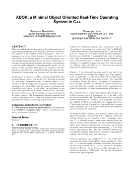
The parallel port
13 12 11 10 9
8
7
6
5
4
3
2
1
contains three
25 24 23 22 21 20 19 18 17 16 15 14
groups of bits:
GND
• data bits (D0-D7)
C0 C1 C2 C3 C4 C5 C6 C7
• status status (S3-S7)
CONTROL PORT
• control bits (C0-C3)
• and ground bits (18-15)
Parallel Port – Data bits
The old PC has LPT parallel port function only for
sending data. Many devices nowadays have
attached to this port and can work bidirectional
(ECP and EPP mode).
Data Port can sink 24 mA at logic 0 and can
source 2.6 mA at logic 1. Notice that the external
device don't try to pull these DP lines to ground
for a long period. The latch IC could be burn.
Parallel Port – Data bits
DATA
PORT
0x0378
pin
num
BIT
SIGNAL
NAME
9
D7
D7
8
D6
D6
7
D5
D5
6
D4
D4
5
D3
D3
4
D2
D2
3
D1
D1
2
D0
D0
INPUT
OUTPUT
These bits may
be input, but
all you will get
is the value
currently
residing in the
output latch,
unless the
interface is
genuinely
bi-directional
Latched TTL
push-pull
outputs with
2.2nF slowdown
capacitors
Parallel Port – Status bits
Status Port use for feedback signal from printer to
the computer. Only 5 MSB bits are used and
accessible.
Only 1 bit is inverting input, ie. S7, use for busy
signal. S6 bit use for acknowledge signal, this
signal used when the printing goes on with
interrupt handshake operation. This is a hardware
interrupt. In some PC/AT's card and bi-directional
card, S2 is used to reflex the state of IRQ, weather
it is on or off state. This bit only for internal use.
Parallel Port – Status bits
STATUS
PORT
0x0379
pin
num
BIT
SIGNAL
NAME
11
S7
BUSY
10
S6
ACK
12
S5
PAPER_OUT
no pull-up not available
13
S4
SELECT
resistor
15
S3
ERROR
na
S2
IRQ
not available
not available
na
S1
not available
not available
not available
na
S0
not available
not available
not available
INPUT
OUTPUT
not available
TTL inputs not available
not available
not available
Parallel Port – Control bits
Control Port is used for controlling the function
of printer. Only 4 bits used by printer and 1 bit
used for interrupt enable flag.
The most important things must be taken if you
connect your own device are : the C0, C1 and
C3 logic are inverting at socket connector
terminal. This means that, when you send logic
1 (high) to this related bit, the logic output
terminal is 0 (low). The C2 and C4 are normal.
Note that, C4 bit only for the adapter card
function.
Parallel Port – Control bits
CONTROL
PORT
0x037A
pin
num
BIT
SIGNAL
NAME
na
C7
not available
not available
not available
na
C6
not available
not available
not available
na
C5
DIRECTION
not available
not available
na
C4
IRQ ENABLE
not available
not available
17
C3
SLCT IN
16
C2
INIT
14
C1
LINE FEED
1
C0
STROBE
may be used
as inputs if
corresponding
output bits are
set to "1
INPUT
OUTPUT
open collector
output with
4.7K pull-up
resistor and
2.2nF slowdown capacitor
Parallel Port – Control bits
Besides that, in some PC/AT's LPT adapter card,
bit C5 is used for control direction (and also in bidirectional card). It means that, if this bit is high,
Data Port can act as input port, the latch output is
tri-state. Data from outside can be read from Data
Port.
Control Port can sink 7 mA at logic 0 and can
source 0.6 mA at logic 1.
Standard Interface Description
LPT printer parallel interface in PC computer type
have specification like this :
• Data transfer rate : 1000 cps (maximum)
• Synchronization : by externally-supplied STROBE
pulses.
• Handshaking -ACK or +BUSY signals.
• Logic level : input data and all interface control
signal are compatible with the TTL level.
Standard Interface Description
Checking LPT Installed
In a new card (bidirectional card), simple send a
byte to DP port and then read back again. If the
result was not an FF Hex or if the result exactly
the same to the byte wrote, then the card is
installed at that port. This happened because, if
the card not installed, the accessing port is a tristate all, there is no connection to the hardware
logic. Tri-state logic interpreted as logic 1.
Software - Java
1. Predisporre una cartella per ogni applicazione che si
intende sviluppare, e copiare al suo interno i file
pPort.class e ioPort.class
2. Copiare (se non è già presente) il file jnpout32pkg.dll
nella cartella C:\WINDOWS\system32, oppure in
alternativa copiarlo nella cartella dell’applicazione
3. Inserire nel programma la direttiva
import jnpout32.*;
import jnpout32.*;
// interfacciamento alla DLL
public class minimo
{
static short dato;
static short indirizzo;
static pPort lpt;
// variabili di classe
public static void main ( String args[ ] )
{
lpt = new pPort (); // istanza di una nuova porta
indirizzo = 0x378; // indirizzo Data Port LPT1
dato = 0x77;
// un dato qualsiasi
lpt.output (indirizzo,dato);
// scrivo il dato
System.out.println ("Scrittura nel Port: " + indirizzo +
" del dato: " + dato);
}
}
dato = (short) lpt.input (indirizzo); // leggo il dato
System.out.println ("Lettura dal Port: " + indirizzo +
" del dato: " + dato);
Definition and declaration of port:
pPort <MiaPorta> = new pPort();
Methods of class pPort :
ParallelPort output method:
public void output (short port, short value)
ParallelPort input method:
public short input (short port)
Set all bits on Data port to zero:
public void setAllDataBits (short value)
Set PinNumber <pin> to <value>:
public void setPin (short pin, short value)
Extension of methods of class pPort :
Set Data Bit at selected index to a value of 1 or 0
while preserving current values of all other Data bits:
public void setDataBit (short index, short value)
Set Control Bit at selected index to a value of 1 or 0
while preserving current values of all other Control bits:
public void setControlBit (short index, short value)
Get Status Bit at selected index to a value of 1 or 0:
public void GetStatusBit (short index, short value)
NB: attention to the type (short) !!!
dato_in = ((<MiaPorta>.input(STATUS_PORT)^0x80) >> 3);
Checking LPT Bi-directional
The bi-directional card used bit C5 to control the direction of
data in Data Port. If the C5 bit is low, the Data Port act as
output port and if it is high, the Data Port is used for input
port.
When the Data Port act as output port, the data is latch at
the output, so if we read this data back from the Data Port,
the data must always the same as that we send. But if Data
Port act as input port, the read data must be FF Hex,
because the latch of Data Port is in tri-state.
Esercizi riepilogativi
1.
2.
3.
4.
5.
Leggere lo stato di tutti i tasti
Individuare lo stato di un solo tasto (bit S6)
Accendere e spegnere dei LED (Data Port)
Ruotare i LED con una frequenza di 1 secondo
Ruotare i LED fino alla pressione di un tasto
particolare
6. Accendere e spegnere tutti i LED del Data Port
seguendo sequenze prestabilite associate ai
vari tasti (proposto)
Scarica