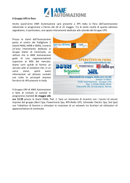
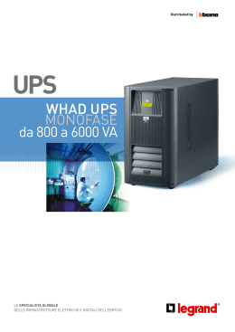
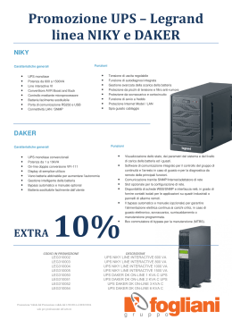
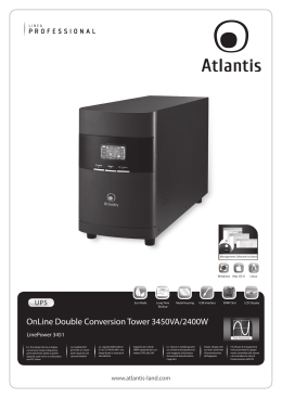
I
MANUALE OPERATIVO
Vi ringraziamo per la scelta del nostro prodotto
La ditta costruttrice è prettamente specializzata nello sviluppo e nella produzione di gruppi statici di
continuità (UPS). Gli UPS di questa serie sono prodotti di alta qualità, attentamente progettati e costruiti allo
scopo di garantire le migliori prestazioni.
Il presente UPS è realizzato in configurazione LINE INTERACTIVE - AVR - STEP WAVE.
Questo manuale contiene le istruzioni dettagliate per l’uso e l’installazione dell’UPS. Per ottenere il massimo
delle prestazioni dalla Vostra apparecchiatura, vogliate leggere e seguire attentamente le istruzioni ivi
descritte. Conservare il presente manuale vicino all’UPS.
© E’ vietata la riproduzione di qualsiasi parte del presente manuale anche se parziale salvo autorizzazione
della ditta costruttrice. Per scopi migliorativi, il costruttore si riserva la facoltà di modificare il prodotto
descritto in qualsiasi momento e senza preavviso.
NORME DI SICUREZZA
La presa di rete cui l’UPS è collegato deve essere dotata di connessione di terra.
All'interno di questa apparecchiatura vi sono tensioni potenzialmente pericolose, anche con UPS spento.
Tutte le riparazioni dovranno essere effettuate esclusivamente da personale autorizzato.
La presa di uscita dell'UPS potrebbe essere in tensione anche quando l'UPS non è collegato alla rete.
In caso di mancanza di rete (funzionamento dell’UPS in emergenza), non staccare il cordone di
alimentazione per garantire la continuità di terra all’utenza collegata.
Evitare che liquidi e/o altri corpi estranei entrino nell'UPS.
Poiché il cordone di alimentazione dell'UPS è inteso come dispositivo di sezionamento, la presa di rete cui
l'UPS è collegato e/o il retro dell’UPS devono essere accessibili e facilmente scollegabili.
In condizioni di pericolo e/o per scollegare l'UPS dalle sorgenti di energia, rete e batterie, sconnettere il
cordone di alimentazione dalla presa di rete o dal retro dell’UPS e spegnere tramite il pulsante OFF.
L'UPS genera una corrente di dispersione di circa 0,5 mA. Per garantire il limite massimo della corrente di
dispersione di 3,5 mA assicurarsi che il carico abbia una corrente di dispersione massima di 3 mA.
Sostituire i fusibili SOLO con altri fusibili dello stesso tipo.
Le batterie sostituite vanno considerate RIFIUTO TOSSICO e trattate di conseguenza.
Non buttare le batterie sul fuoco: possono esplodere.
Non tentare di aprire le batterie: sono prive di manutenzione. Inoltre l’elettrolita è pericoloso per la pelle e
per gli occhi, e può risultare tossico.
Utilizzare l’UPS all’interno delle specifiche previste secondo quanto prescritto dal presente manuale d’uso.
3
GB
OPERATING MANUAL
We thank you for having chosen our product
The manifacturer is particularly specialized in the development and production of Uninterruptible Power
Supply (UPS). These UPS system are high quality products, carefully designed to meet the highest
performance standards.
This UPS has been built according to the LINE INTERACTIVE - AVR - STEP WAVE configuration.
This user’s manual contains detailed instructions on UPS operation and care. In order to get the best
performance from your UPS, please read and follow carefully the instructions described in the following
pages. It is recommended that you keep this manual beside your equipment.
© No part of this manual may be reproduced in any way without the approval of the manufacturer. Data and
drawings are subject to changes without notice and without obligation on the manufacturer’s.
SAFETY REGULATIONS
This equipment should be operated by any individuals with no previous training.
The mains socket to which the UPS is connected must be grounded.
Dangerous voltage may be present in this device even while the UPS is off.. All repairs must be carried out
by authorized staff only.
The output socket of the UPS could be powered even when the UPS is not connected to the mains.
In case of mains failure (battery mode), do not disconnect the input cable from mains so to ensure the earth
connection to the loads supplied.
Do not let liquids and/or other foreign bodies into the UPS.
As the mains cable of the UPS is considered to be a sectioning device, the mains socket to which the UPS is
connected and/or the rear of the UPS must be accessible and easy to disconnect.
With mains voltage present and the UPS is connected to the mains (even with the UPS off), there are
potentially dangerous voltages inside the UPS.
Under conditions of danger and/or to disconnect the UPS from the energy sources, (the mains and batteries),
unplug the mains cable from the mains socket or the rear of the UPS, and power it off using the OFF button.
Attention, hazardous through electric shock. Also with disconnection of this unit from the mains, hazardous
voltage still may be accessible through supply from battery. The battery supply should be therefore
diconnected in the plus and minus pole at the quick connectors of the battery when maintenance or service
work inside the UPS is necessary.
The UPS generates a leakage current of about 0,5 mA. "With the installation of this equipment it should be
prevented, that the sum of the leakage current of the UPS an the connected consumer exceeds 3.5mA."
Replace the fuses ONLY with other fuses of the same type.
Replaced batteries are to be considered TOXIC WASTE and handled accordingly.
When replacing the batteries, use the same number and the following type of batteries.
Do not dispose of batteries in a fire, the battery may explode.
Do not open or mutilate the battery or batteries, released electrolyte is harmful to the skin and eyes.
Use the UPS in accordance with the specifications shown in the technical characteristics table.
4
D
BEDIENUNGSANLEITUNG
Wir danken Ihnen dafür, daß Sie unserem Produkt den Vorzug gegeben haben.
Die Herstellerfirma ist auf die Produktion von unterbrechungsfreien Stromversorgungen (USV) spezialisiert.
Die USV-Geräte dieser Serie sind Hochqualitätsprodukte, mit Sorgfalt gebaut, um Höchstleistungen zu
erbringen.
Diese USV-Geräte sind in folgender Konfiguration erhältlich: LINE INTERACTIVE - AVR - STEP WAVE.
Das vorliegende Handbuch enthält detaillierte Anweisungen zu Betrieb und Aufstellung der USV-Geräte. Ihr
Gerät erbringt Höchstleistungen, wenn Sie diese Anweisungen aufmerksam lesen und befolgen. Das
vorliegende Handbuch ist in der Nähe des USV-Geräts aufzubewahren.
© Diese Bedienungsanweisung darf ohne Zustimmung des Herstellers auch auszugsweise nicht
vervielfälttight werden. Änderung dervtechnichen Daten und Zeichnungen vorbehalten.
SICHERHEITSHINWEISE
Diese Geräte sollten durch Einzelpersonen ohne vorhergehende Schulung bedient werden
Die Steckdose, an der das Versorgungskabel der USV angeschlossen wir , muß geerdet sein.
Im Inneren der USV treten gefährliche Spannungen auf. Evtl. Reparaturarbeiten dürfen ausschließlich nur
durch dafür ausgebildetes Personal vorgenommen werden.
Die Ausgangssteckdose der USV kann auch dann unter Spannung stehen, wenn die Netzversorgung der
USV unterbrochen ist.
Es muß unbedingt darauf geachtet werden, daß keine Flüssigkeiten und/oder Fremdkörper in die USV
gelangen.
Im Falle eines Netzausfalls (Batteriebetrieb) darf auf keinen Fall das Netzversorgungskabel von der USV
abgetrennt werden. Nur so ist sichergestellt, daß der Verbraucher am Schutzleiter anliegt.
Da das Versorgungskabel der USV als Unterbrechungsvorrichtung gedacht ist, muß der Raum um die
Netzsteckdose, an der die USV angeschlossen wird, und/oder die Rückseite der USV leicht zugänglich sein,
um eine schnelle Stromunterbrechung zu ermöglichenBei vorhandener Netzspannung und angeschlossenem Versorgungskabel sind im Inneren der USV ständig
gefährliche Spannungen vorhanden.
In Gefahrensituationen und/oder wenn die Verbindung zwischen der USV und den Energie-quellen, d.h.
zwischen Netz oder Batterie unterbrochern werden muß, sollte der Stecker des Versorgungskabels aus der
Netzsteckdose oder aus der Steckdose an der Rückseite der USV gezogen und die OFF-Taste gedrückt
werden.
Achtung: Stromstossgefahr. Auch mit der Trennung dieses Systems vom Stromnetz kann gefährliche
Spannung noch zugänglich sein durch die Batterieversorgung. Daher sollte sie am Plus- und Minuspol von
den Schnell-Steckverbindern der Batterie getrennt werden, wenn Wartungs- oder Servicearbeiten innerhalb
der USV erforderlich sind.
Die USV erzeugt einen Leckstrom von 0,5 mA. Mit der Installation dieser Geräte soll verhindert werden,
dass der gesamte Leckstrom einer USV und des angeschlossenen Verbrauchers 3,5mA übersteigt.
Die Sicherungen dürfen AUSCHLIEßLICH nur durch Sicherungen des gleichen Typs ersetzt werden
Bei den ausgetauschten Batterien handelt es sich um GIFTIGEN SONDERMÜLL, der ent-sprechend
entsorgt werden muß. Beim Ersatz der Batterien dieselbe Anzahl und den folgenden Typ von Batterien
benutzen
Keine Batterien bei Feuer benutzen, die Batterie kann explodieren.
Die Batterie oder Batterien nicht öffnen oder beschädigen, ausgelaufener Elektrolyt ist für Haut und Augen
schädlich.
Eine Batterie kann ein Risiko darstellen, da Stromstossgefahr und hoher Kurzschlussstrom vorhanden sind.
Bedienungsanleitung enthaltenen Spezifikationen aufgheführt sind.
5
F
MANUEL DE SERVICE
Nous vous remercions d'avoir choisi notre produit.
Le fabricant est essentiellement spécialisé dans l'élaboration et dans la production de groupes de continuité
statiques (UPS). Les UPS de cette série sont des produits de haute qualité, conçus et fabriqués avec le plus
grand soin, de façon à assurer les meilleures performances.
Cet ASI est réalisé avec LINE INTERACTIVE - AVR - STEP WAVE.
Ce manuel contient les instructions détaillées nécessaires à l'utilisation et à l'installation de l'UPS. Pour que
votre appareil fournisse le meilleur de lui-même, veuillez consulter et respecter scrupuleusement les
instructions qui y sont décrites. Conserver ce manuel à proximité de l'UPS.
© Toute reproducion même partielle de ce manuel est interdite sans autorisation préable du fabricant. Le
fabricant se réserve le droit de modifier sans préavis les caractéristiques et schémas repris dans ce manuel.
NORME DE SECURITE
La prise de secteur à laquelle l’ASI est branché, doit être fournie d’une connexion de mise à la terre.
Cet appareil contient des tensions potentiellement dangereuses, même lorsque l’ASI est éteint.. Toutes les
réparations doivent être exclusivement effectuées par un personnel habilité.
La prise de sortie de l'UPS peut être sous tension même lorsque l'UPS n’est pas connecté au réseau.
En case d’absence du réseau (fonctionnement de l’UPS sur batteries) ne pas débrancher le cordon
d’alimentation afin d’assurer la continuité de la liaison de terre jusqu’à l’utilisation.
Eviter que des liquides et/ou autres substances étrangères ne pénètrent à l’intérieur de l'UPS.
Dans la mesure où le cordon d’alimentation de l’UPS sert de dispositif de sectionnement, la prise du réseau à
laquelle l’UPS est relié et/ou la face arrière de l’UPS doivent rester accessibles et faciles à désactiver.
Lorsque le secteur est present et que l’UPS est relié à ce dernier, l’UPS contient des tensions potentiellement
dangereuses même s’il est éteint.
En cas de danger et/ou pour déconnecter l’UPS des sources d’énergie, à savoir, réseau et batteries,
débrancher le cordon d’alimentation de la prise du réseau ou de la face arrière de l’UPS et éteindre à l’aide
du bouton-poussoir OFF. L'UPS génère un courant de fuite d’environ 0,5 mA. Afin de maintenir la limite
maximale du courant de dispersion à 3,5 mA, s’assurer que le courant maximum de dispersion de la charge
soit de 3 mA.
Remplacer les fusibles UNIQUEMENT par des fusibles de même type.
Les batteries remplacées doivent être considérées comme DECHET TOXIQUE et traitées en conséquence.
Ne pas jeter les batteries au feu: elles risquent d’exploser.
Ne pas tenter d’ouvrir les batteries: Elles ne sont pas réparables. En outre, l’électrolyte
est dangereuse aussi bien pour la peau que pour les yeux, et peut s’avérer toxique.
Utiliser l’UPS en respectant les spécifications reportées dans le tableau des caractéristiques techniques qui se
trouve dans le présent manuel.
6
E
MANUAL DE USO
Le agradecemos por la elección de nuestro producto.
La empresa constructora está especializada en el desarrollo y la producción de grupos estáticos de
continuidad (UPS). Los UPS de esta serie son productos de alta calidad, atentamente proyectados y
construídos con la finalidad de garantizar las mejores prestaciones.
Este SAI es realizado en configuración LINE INTERACTIVE - AVR - STEP WAVE
Éste manual contiene las instrucciones detalladas para el uso y la instalación del UPS. Para obtener el
máximo de las prestaciones de vuestro equipo, quiera Ud. leer y seguir atentamente las instrucciones aquí
descriptas. Conservar el presente manual en un lugar cercano del UPS.
© Salvo autorización del constructor está prohibida la reproduccíon de qualquier parte del presente manuel,
aún en forma parcial. Los datos y diseños reportados pueden sufrir variaciones sin preaviso y no
comprometen al constructor.
NORMAS DE SEGURIDAD
La toma de red a la cual el SAI es conectado debe ser equipada con conexión de tierra.
Al interior de este equipo hay tensiones potencialmente peligrosas, aún con el SAI apagado.. Todas las
reparaciones deberán ser efectuadas exclusivamente por personal autorizado.
La toma de salida del UPS podría estar en tensión aún cuando el UPS no está conectado a la red.
En caso que el UPS està trabajando de bateria, no desconectar el cable de red. De esta forma se continuarà a
garantizar la conexion a tierra a los aparados conectados.
Evitar que líquidos y/u otros cuerpos extraños entren en el UPS.
Ya que el cable de alimentación del UPS se entiende como un dispositivo de seccionamiento, la toma de red
a al cual el UPS está conectado y/o la parte posterior del UPS deben ser accesibles y de fácil desconexión.
Con la red presente y el UPS conectado a la red, también si el UPS està apagado, se encuentran tensiones
potencialmente peligrosas en el interior del UPS.
En condiciones de peligro y/o para desconectar el UPS de las fuentes de energía, red y baterías, desconectar
el cable de alimentación de la toma de red o de la parte posterior del UPS y apagar a través del pulsador
OFF.
El UPS genera una corriernte de dispersión de aproximadamente 0,5mA. Para garantizar el límite máximo de
la corriente de dispersión de 3,5mA, asegurarse que la carga tenga una corriente de dispersión máxima de
3mA.
Remplazar los fusibles SOLO con otros fusibles del mismo tipo
Las baterías remplazadas deben ser consideradas DESECHO TOXICO y tratadas por consecuente.
Nunca echar las baterías en el fuego : pueden exploder.
No intentar abrir las baterías : no llevan mantenimiento. Además el electrolita es peligroso para la piel y para
los ojos y puede resultar tóxico.
Utilizar el SAI al interior de las especificaciones previstas según las instrucciones de este manual de empleo.
7
GR
ΕΓΧΕΙΡΙΔΙΟ ΧΡΗΣΗΣ
Σας ευχαριστούμε για την επιλογή του προιόντος μας
Ο κατασκευαστικός οίκος είναι εξειδικευμένος στην ανάπτυξη και στην παραγωγή στατικών συνόλων
συνέχειας (UPS).
Τα UPS αυτής της σειράς αποτελούν προιόντα υψηλής ποιότητας, σχεδιασμένα και κατασκευασμένα με
ιδιαίτερη φροντίφα με σκοπό την εξασφάλιση των καλύτερων αποδόσεων.
Το παρόν UPS είναι κατασκευασμένο σε μορφοσχηματισμό LINE INTERACTIVE - AVR - STEP WAVE.
Αυτό το εγχειρίδιο περιέχει τις λεπτομερείς οδηγίες για την χρήση και την εγκατάσταση του UPS. Για να
επιτύχετε το μέγιστο των επιδόσεων της συσκευής σας, διαβάστε και ακολουθήστε προσεχτικά αυτές τις
οδηγίες χρήσης. Φυλάξτε αυτό το εγχειρίδιο κοντά στο UPS.
(c) Απαγορεύεται η αναπαραγωγή οποιουδήποτε τμήματος του παρόντος εγχειριδίου έστω και σε μερική
μορφή εξαιρέσει εξουσιοδότησης του κατασκευαστικού οίκου. Για λόγους βελτίωσης του προιόντος, ο
κατασκευαστής επιφυλάσσεται του δικαιώματος να τροποποιήσει το περιγραφόμενο προιόν ανά πάσα
στιγμή και άνευ προειδοποιήσεως.
ΚΑΝΟΝΕΣ ΑΣΦΑΛΕΙΑΣ
Η πρίζα δικτύου στην οποία θα συνδεθεί το UPS θα πρέπει να διαθέτει γείωση.
Στο εσωτερικό αυτής της συσκευής υπάρχουν τάσεις ιδιαίτερα επικίνδυνες, ακόμα και όταν τα UPS είνα
σβηστά. Όλες οι επιδιορθώσεις θα πρέπει να εκτελούνται αποκλειστικά και μόνο από προσωπικό
εξουσιοδοτημένο.
Η πρίζα εξόδου του UPS είναι δυνατόν να βρίσκεται υπό τάση ακόμα και όταν το UPS δεν είναι συνδεδεμένο
στο δίκτυο ρεύματος.
Σε περίπτωση πτώσης του δικτύου ρεύματος (λειτουργεία του UPS σε κατάσταση ανάγκης) μη αφαιρέσετε
το καλώδιο τροφοδοσίας, για την εξασφάλιση της συνέχειας γείωσης της συνδεδεμένης συσκευής.
Αποφύγετε την εισαγωγή υγρών ουσιών ή και άλλων ξένων σωμάτων στο UPS.
Επειδή το καλώδιο τροφοδοσίας του UPS λαμβάνεται ως σύστημα κατάτμισης, η πρίζα του δικτύου στην
οποία το UPS είναι συνδεδεμένο καθώς και το πίσω μέρος του UPS θα πρέπει να είναι προσβάσιμα και
εύκολα αποσυνδεόμενα.
Σε περίπτωση κινδύνου ή και για να αποσυνδέσετε το UPS από πηγές ενέργειας, δίκτυα και συσσωρευτές,
αποσυνδέσετε το καλώδιο τροφοδοσίας από την πρίζα δικτύου ρεύματος ή από το πίσω μέρος τους UPS και
σβήσετε δια του πλήκτρου OFF.
Το UPS δημιουργεί ένα ρεύμα διαρροής 0,5 mA. Για την εξασφάλιση του μέγιστου ορίου ρεύματος διαρροής
3,5 mA βεβαιωθείτε ότι το φορτίο διαθέτει ένα ρεύμα μέγιστης διαρροής 3 mA.
Αντικαταστήσετε τις ασφάλειες ΜΟΝΟ με άλλες ασφάλειες του ίδιου τύπου.
Οι συσσωρευτές που έχουν αντικατασταθεί θεωρούνται ΤΟΞΙΚΑ ΑΠΟΒΛΗΤΑ και αντμετωπίζονται κατά τον
πρέποντα τρόπο.
Μην πετάξετε τους συσσωρευτές στη φωτιά: υπάρχει κίνδυνος να εκραγούν.
Μην προσπαθήσετε να ανοίξετε τυς συσσωρευτές: δεν συντηρούνται. Επίσης, ο ηλεκτρολύτης είναι
επικίνδυνος στο δέρμα και στα μάτια, και μπορεί να είναι επίσης τοξικός.
Χρησιμοποιήσετε το UPS εντός των πλαισίων των προβλεπομένων προδιαγραφών του παρόντος
εγχειριδίου χρήσης.
8
S
BRUKSANVISNING
Vi tackar dig för valet av vår produkt.
Tillverkaren är specialiserad på utveckling och produktion av reservströmkällor (UPS). Denna serie av UPS
består av produkter av hög kvalitet, noggrant konstruerade och tillverkade för att garantera bästa möjliga
prestanda. Denna UPS är tillverkad med konfigurering för LINE INTERACTIVE - AVR - STEP WAVE.
Denna bruksanvisning innehåller detaljerade anvisningar för installering och användning av UPS. För att
erhålla maximala prestationer från din apparat ska bruksanvisningen läsas och följas noggrant. Förvara
denna bruksanvisning i nära anslutning till UPS.
© All reproduktion, även delvis, av denna bruksanvisning är förbjuden utan tillverkarens samtycke.
Tillverkaren förbehåller sig rätten att förändra produkten med avsikt att förbättra produkten.
SÄKERHETSFÖRESKRIFTER
Vägguttaget som apparaten ansluts till ska vara jordanslutet.
Inuti denna apparat finns det spänningar som är mycket farliga, även då UPS är avstängd. Alla reparationer
får endast utföras av auktoriserad personal.
Eluttaget för utgående ström på UPS kan vara spänningssatt även när UPS inte är kopplad till elnätet.
För att garantera en oavbruten jordanslutning får inte elsladden tas ut ur nätuttaget då nätströmmen är
avbruten (vid nödfall med UPS aktiverad).
Undvik att vätskor och/eller andra främmande ämnen tränger in i UPS.
Eftersom nätsladden för UPS är avsedd som frånskiljare måste nätuttaget som UPS är ansluten till och/eller
baksidan av UPS vara lättillgängliga och de måste vara enkla att koppla ur.
Vid fara och/eller för att koppla bort UPS från strömkälla, elnät och batteri ska nätsladden tas ur nätuttaget
eller tas ur på baksidan av UPS och apparaten ska stängas av med tryckknapp OFF.
UPS generar en läckström på cirka 0,5 mA. För att garantera en max. läckström på 3,5 mA måste du försäkra
dig om att belastningen har en läckström på max. 3 mA.
Säkringar får ENDAST bytas ut mot säkringar av samma typ.
Utbytta batterier ska betraktas som GIFTIGT AVFALL och ska behandlas som sådana.
Släng inte batterierna på eld: de kan explodera.
Försök inte att öppna batterierna: de behöver inte underhållas. Dessutom är batterisyran farlig för huden och
ögonen och kan vara giftig.
Använd UPS inom de användningsområden som den enligt bruksanvisningen är avsedd för.
9
NL
BEDIENINGSHANDLEIDING
Wij wensen u van harte te bedanken voor uw keus voor een product van ons
De fabrikant is specifiek gespecialiseerd in de ontwikkeling en productie van statistische onderbrekingsvrije
voedingsbeveiligers (UPS).
De UPS van deze serie zijn hoogwaardige, zorgvuldig ontworpen en gefabriceerde producten die de beste
prestaties garanderen.
Deze UPS is ontwikkeld met de LINE INTERACTIVE - AVR - STEP WAVE configuratie.
Deze handleiding bevat gedetailleerde instructies voor het gebruik en de installatie van de UPS. Om
verzekerd te zijn van de beste prestaties van uw apparatuur verzoeken wij U de instructies aandachtig door te
lezen en uit te voeren. Bewaar deze handleiding in de buurt van de UPS.
© De gehele of gedeeltelijke verveelvoudiging van deze handleiding zonder toestemming van de fabrikant is
verboden. Met het oog op productverbeteringen behoudt de fabrikant zich het recht voor om op elk gewenst
moment en zonder kennisgeving vooraf wijzigingen op het product aan te brengen.
VEILIGHEIDSNORMEN
Het stopcontact waarop de UPS is aangesloten dient te zijn uitgerust met een aardaansluiting.
Binnenin het apparaat bevinden zich onderdelen met potentieel gevaarlijke spanningen, ook als de UPS is
uitgeschakeld. Reparaties mogen dan ook uitsluitend door bevoegd personeel worden uitgevoerd.
Het uitgangsstopcontact van de UPS kan ook onder spanning staan als de UPS niet is aangesloten op het
elektriciteitsnet.
Bij een stroomuitval (werking van de UPS in een noodsituatie), mag de voedingskabel niet worden
losgemaakt om een ononderbroken aardaansluiting van het aangesloten toestel te garanderen.
Zorg ervoor dat er geen vloeistoffen en/of andere voorwerpen in de UPS terechtkomen.
Daar de voedingskabel van de UPS als sectie-inrichting fungeert moeten het voedingsstopcontact waarop de
UPS is aangesloten en/of de achterkant van de UPS toegankelijk zijn en gemakkelijk kunnen worden
losgekoppeld.
Bij gevaar en/of om de UPS van de energiebronnen, netwerk en accu’s, los te koppelen, moet de
voedingskabel uit het voedingsstopcontact of uit de achterkant van de UPS worden verwijderd en moet hij
met behulp van de drukknop OFF worden uitgeschakeld.
De Ups levert een lekstroom van circa 0,5 mA.Om verzekerd te zijn van de maximale limiet van de
lekstroom van 3,5 mA moet ervoor worden gezorgd dat de belasting een maximale lekstroom heeft van
3 mA
Vervang de zekeringen UITSLUITEND met andere vergelijkbare zekeringen.
De vervangen accu’s zijn GIFTIG AFVAL en moeten als zodanig worden behandeld.
Gooi de accu’s nooit in het vuur: ze zouden kunnen exploderen.
Probeer nooit om de accu’s te openen: zij zijn vrij van onderhoud. De elektrolyt is gevaarlijk voor huid en
ogen en kan giftig blijken.
De UPS overeenkomstig de voorschriften van deze bedieningshandleiding gebruiken binnen de beperkingen
van de voorziene specificaties.
10
P
MANUAL OPERACIONAL
Agradecemos-lhes por terem escolhido o nosso produto
O fabricante é especializado no desenvolvimento e na produção de fontes de alimentação não-interrompíveis
(UPS).
As UPS desta série são produtos de alta qualidade, acuradamente projectadas e fabricadas, a fim de garantir
os melhores desempenhos.
O presente UPS é realizada na configuração LINE INTERACTIVE - AVR - STEP WAVE.
Este manual contém as instruções detalhadas para o uso e instalação da UPS. Para obter o melhor
desempenho do seu aparelho, queira ler e seguir cuidadosamente as instruções aqui contidas. Conservar o
presente manual próximo a UPS.
© É proibida a reprodução de qualquer parte do presente manual, mesmo se parcial, salvo autorização do
fabricante. Para fins de melhoria, o fabricante reserva-se o direito de modificar o produto descrito a qualquer
momento e sem aviso prévio.
NORMAS DE SEGURANÇA
A tomada de rede à qual está ligado a UPS deve ser dotada de ligação à terra.
Na parte interna deste aparelho há tensões potencialmente perigosas, mesmo com a UPS desligada. Todas as
reparações deverão ser feitas exclusivamente por pessoal autorizado.
A tomada de saída da UPS pode ficar com tensão mesmo quando a UPS estiver desligada da rede.
Em caso de falta de alimentação eléctrica (funcionamento da UPS em emergência), não desligar o fio de
alimentação para poder garantir a continuidade de terra ao aparelho ligado.
Evite que líquidos e/ou outros corpos estranhos entrem na UPS.
Visto que o fio de alimentação da UPS é considerado um dispositivo de corte, a tomada da rede à qual a UPS
está ligada e/ou a parte posterior da UPS devem ficar acessíveis e fáceis de desligar.
Em condições de perigo e/ou para desligar a UPS das fontes de energia, rede e baterias, desligar o fio de
alimentação da tomada da rede ou da parte posterior da UPS e desligar mediante o botão OFF.
A UPS gera uma corrente de dispersão de aproximadamente 0,5mA. Para garantir o limite máximo da
corrente de dispersão de 3,5mA, certificarse de que a carga tenha uma corrente de dispersão máxima de
3 mA.
Substituir os fusíveis SOMENTE por outros fusíveis do mesmo tipo.
As baterias substituídas são RESÍDUOS TÓXICOS e devem ser tratadas como tais.
Não deite as baterias no fogo, pois podem explodir.
Não tente abrir as baterias, pois não é necessário fazer a manutenção. Para além disso, o electrólito é
perigoso para a pele e para os olhos, e pode resultar tóxico.
Utilizar a UPS em conformidade com as especificações previstas segundo o quanto estabelecido no presente
manual.
11
12
ITALIANO
MANUALE D’USO
CONTENUTO DELLA CONFEZIONE
14
DESCRIZIONE UPS
14
REQUISITI PER L'INSTALLAZIONE
16
INSTALLAZIONE
16
FUNZIONAMENTO
17
ALLARMI
17
LOCALIZZAZIONE GUASTI
18
IMMAGAZZINAMENTO
18
CARATTERISTICHE TECNICHE
19
13
CONTENUTO DELLA CONFEZIONE
¾ UPS
¾ N°2 cavi di uscita IEC-IEC
¾ N°1 manuale d’uso
DESCRIZIONE UPS
VISTA FRONTALE
1
3
2
4
1 Indicatore di "SOSTITUZIONE BATTERIA" (LED ROSSO)
Questo LED si accende quando la batteria del Gruppo di Continuità non è più efficiente e deve essere
sostituita (contattare l’assistenza tecnica) o in presenza di un sovraccarico.
2 Indicatore di "FUNZIONAMENTO BATTERIA " (LED giallo)
Questo LED si accende quando il Gruppo di Continuità alimenta i carichi tramite la batteria.
3 Indicatore di "LINEA NORMALE" (LED VERDE)
Questo LED si accende quando la tensione di alimentazione di linea è normale.
4 Interruttore "ON/OFF"
Premere questo interruttore per accendere o spegnere il Gruppo di Continuità.
14
VISTA POSTERIORE
5 INTERFACCIA COMPUTER (solo per modelli 40U Plus – 60U Plus – 80U Plus)
Permette il collegamento ad un computer tramite interfaccia seriale USB.
6 PRESE DI USCITA
7 SPINA D’INGRESSO
8 FUSIBILE DI INGRESSO RETE
15
REQUISITI PER L'INSTALLAZIONE
Installare l'UPS tenendo presente le seguenti indicazioni:
¾ l'UPS deve essere posizionato su di una superficie piana e stabile.
¾ Evitare di posizionare l'UPS in luoghi esposti alla luce diretta del sole o ad aria calda.
¾ Mantenere la temperatura ambiente tra 0°C e 40°C.
¾ L'umidità ambiente non deve superare il 90%.
¾ Evitare ambienti polverosi.
¾ Posizionare l'UPS ad almeno 5cm dalle pareti circostanti, allo scopo di lasciare libere le feritoie e
permettere quindi una ventilazione adeguata.
¾ Evitare di porre l'UPS stesso o qualsiasi altro oggetto pesante sul cavo di alimentazione.
¾ Il cavo che collega il carico all’UPS deve avere una lunghezza max. di 10 mt.
INSTALLAZIONE
Ispezione
Ispezionare il Gruppo di Continuità al momento del ricevimento. L’imballaggio è riciclabile ed è stato
studiato per un trasporto sicuro dell’UPS in condizioni normali di transito; consigliamo quindi di conservare
lo stesso nel caso l’unità dovesse essere trasportata in futuro. In caso contrario smaltirlo in maniera idonea.
Collocazione
Installare il Gruppo di Continuità tenendo presente gli avvertimenti sopra citati nel paragrafo relativo ai
requisisiti di instalazione.
Collegamento alla Rete
Per alimentare l’UPS, collegare la spina d’ingresso di alimentazione alla presa di rete.
N.B.: Il cavo di alimentazione non è incluso. Per il collegamento è possibile utilizzare il cavo di
alimentazione del PC.
Caricare la batteria
Il Gruppo di Continuità effettua la ricarica la batteria ogni qualvolta viene collegato all’alimentazione di rete.
Per un risultato ottimale, caricare la batteria per 6-8 ore al primo uso.
Collegare i carichi
Inserire i carichi nelle prese di uscita sul retro del Gruppo di Continuità.
Attenzione: Non collegare una stampante laser,una fotocopiatrice o un fax laser al Gruppo di Continuità
assieme ad altre periferiche del computer. Queste apparecchiature assorbono occasionalmente una
quantità molto maggiore di energia rispetto a quando sono a riposo, cosa che potrebbe sovraccaricare il
Gruppo di Continuità.
Collegamento dell’Interfaccia Computer (solo per modelli 40U Plus – 60U Plus – 80U Plus)
L’UPS può essere collegato tramite un cavo di collegamento USB ad un computer per funzioni di
monitoraggio e shutdown del sistema operativo. È possibile scaricare il software di gestione ed il
relativo manuale dal sito internet www.riello-ups.com.
N.B.: Il collegamento dell’interfaccia computer è facoltativo, il Gruppo di Continuità funziona
adeguatamente anche senza collegamento dell’interfaccia computer.
16
FUNZIONAMENTO
Accensione
Dopo aver connesso il Gruppo di Continuità alla presa di rete, per accendere il Gruppo di Continuità
premere l’interruttore di on/off, questo rimarrà premuto e si accenderà il LED di "LINEA NORMALE".
Il Gruppo di Continuità può essere acceso anche in mancanza di rete
Spegnimento
Premere nuovamente l’interruttore di on/off, questo tornerà nella sua posizione di riposo e i LED di "LINEA
NORMALE" o "FUNZIONAMENTO DA BATTERIA" si spegneranno.
ALLARMI
"FUNZIONAMENTO DA BATTERIA" (Bip ogni 5 secondi)
In modalità di "FUNZIONAMENTO DA BATTERIA", il LED GIALLO si accende e il Gruppo di
Continuità emette un allarme acustico. L’allarme cessa quando il Gruppo di Continuità ritorna in modalità di
funzionamento di LINEA NORMALE.
"BATTERIA SCARICA" (Bip ogni secondo)
In modalità di "FUNZIONAMENTO DA BATTERIA", quando la batteria sta per scaricarsi, il Gruppo di
Continuità emette un bip veloce finché il Gruppo di Continuità si arresta per batteria scarica o finché non
viene ripristinata la modalità di funzionamento di LINEA NORMALE.
"SOVRACCARICO" (Bip molto veloce o continuo non tacitabile)
Quando il Gruppo di Continuità è in sovraccarico (i carichi collegati superano la massima capacità
nominale), il Gruppo di Continuità emette un suono continuo per avvertire che è in corso una condizione di
sovraccarico. Scollegare qualsiasi dispositivo non essenziale dal Gruppo di Continuità per eliminare il
sovraccarico.
TACITAZIONE (via software) (solo per modelli 40U Plus – 60U Plus – 80U Plus)
Utilizzare il comando tacitazione “buzzer abilitato/disabilitato” (vedi guida in linea del software) per
sileziare l’UPS in funzionamento da batteria. La funzione di allarme acustico verrà riabilitata
automaticamente ad ogni cambio di stato della macchina (Es.: quando il Gruppo di Continuità ritorna in
modalità di funzionamento di LINEA NORMALE).
17
LOCALIZZAZIONE GUASTI
PROBLEMA
L’UPS non si
accende
CAUSA POSSIBILE
L’interruttore ”ON/OFF” non è stato
premuto fino in fondo
Guasto dell’UPS
Cavo di potenza allentato
Gruppo di Continuità
sempre in modalità
batteria
Durata di
funzionamento con
batteria tampone
troppo breve
Allarme sonoro
sempre attivo
LED rosso ”batteria
guasta” acceso
Fusibile di ingresso rete bruciato
Tensione di linea troppo alta, troppo
bassa o black-out
Guasto dell’UPS
Batteria non completamente carica
Batteria danneggiata
MISURE DA ADOTTARE
Premere l’ interruttore ”ON/OFF”
correttamente
Contattare l’assistenza tecnica
Inserire a fondo il cavo di
alimentazione nella presa di rete
Sostituire il fusibile
Condizione normale
Contattare assistenza tecnica
Mettere sotto carica il Gruppo di
Continuità per almeno 6 ore
Sostituire la batteria, contattare
l’assistenza tecnica
Sovraccarico
Eliminare i carichi non essenziali
Guasto batteria
Sostituire la batteria, contattare
l’assistenza tecnica
Nel caso si verifichino problemi o malfunzionamenti diversi da quelli elencati oppure non si riesca ad
effettuare le operazioni sopra descritte fare riferimento al servizio di assistenza tecnica allegando una
documentazione completa del problema.
IMMAGAZZINAMENTO
Condizioni di immagazzinaggio
Conservare il Gruppo di Continuità coperto e in posizione orizzontale, in un luogo fresco e asciutto, con la
batteria completamente carica. Prima della collocazione a magazzino, caricare il Gruppo di Continuità per
almeno 6 ore. Spegnere il Gruppo di Continuità e staccare tutti i cavi ad esso collegati.
Immagazzinaggio prolungato
Durante lo stoccaggio prolungato in ambienti la cui temperatura è compresa tra -15 e +20°C, caricare la
batteria del Gruppo di Continuità ogni 12 mesi.
Durante lo stoccaggio prolungato in ambienti la cui temperatura è compresa tra +20 e +30°C, caricare la
batteria del Gruppo di Continuità ogni 6 mesi.
Durante lo stoccaggio prolungato in ambienti la cui temperatura è compresa tra +30 e +45°C, caricare la
batteria del Gruppo di Continuità ogni 3 mesi.
18
CARATTERISTICHE TECNICHE
MODELLO
Serie (codice tipo)
INGRESSO
Win Dialog 50
USY1…
230V +20%/ -25%
Frequenza
50 o 60Hz +/-5% (autoappresa)
3A
2.4 A
BATTERIA
Step wave 230Vac +/-5%
Frequenza
(da batteria)
50 or 60Hz +/-0.5% (autoappresa)
INTERFACCIA
4.8 A
AVR incrementa automaticamente la tensione di uscita del 17% se la tensione di
Regolazione di tensione ingresso scende dal -10% al -26% del valore nominale. AVR abbassa la tensione di
AVR
uscita del 15% se la tensione di ingresso è dal +9% al +20% più alta del valore
nominale
8 ms tipici, 10ms max, incluso tempo di rilevazione
Potenza nominale VA
500
400
600
800
Potenza nominale W
300
240
360
480
Filtro EMI/RFI
10dB at15MHz, 50dB at 30MHz
Protezione al
sovraccarico e al corto
circuito
Rete presente: Fusibile per protezione sovraccarico e corto circuito
Da batteria: l’UPS si spegne dopo 30 secondi con carico compreso tra 100 ~ 110%
del nominale, dopo 5 secondi se >110%, immediatamente in caso di corto circuito.
Tipo
Al piombo, ermetica, senza necessità di manutenzione
Modello
12V 7Ah
12V 4,5Ah
12V 7Ah
12V ≥9Ah
Tempo di ricarica tipico
6-8 ore
Protezioni
protezione di scarica, indicatore di sostituzione batteria
Peso netto (Kg)
5,3
4,2
5,5
6,1
Peso con imballo (Kg)
-
-
-
-
CARATTERISTICHE Dimensioni(mm) WxDxH
FISICHE
ALLARMI
Win Dialog 80U
Plus USY2…
3.6 A
Tensione
(da batteria)
Tempo di intervento
PROTEZIONI E
FILTRI
Win Dialog 60U
Plus USY2…
Tensione
Corrente massima
USCITA
Win Dialog 40U
Plus USY2…
152x110x325 mm
Spina di ingresso
IEC 320-10A
Prese di uscita
N°3 x IEC 320-10A
Funzionamento da
batteria
Segnale sonoro lento (circa 0.2Hz)
Batteria scarica
Segnale sonoro rapido (circa 1Hz)
Sovraccarico <110%
Segnale sonoro rapido (circa 1Hz)
Sovraccarico >110%
Suono continuo
Tacitazione buzzer
-
Interfaccia USB
-
via software
via software
via software
Porta comunicazione bi-direzionale
CONDIZIONI
AMBIENTALI (1)
Condizioni ambientali
6,000 metri max. altitudine, 0-90% umidità non condensante
0-40°C
VARIE
Rumorosità
<40dBA (1m dalla sorgente )
(1) per prolungare la vita utile della batteria, mantenere una temperatura di esercizio/stoccaggio di 20-25°C e
mantenere il collegamento alla rete per preservare la carica della batteria.
19
20
ENGLISH
USER’S MANUAL
CONTENTS OF THE PACKAGING
22
PRESENTATION
22
INSTALLATION REQUIREMENTS
24
INSTALLATION
24
FUNCTIONING
25
ALARMS
25
LOCATING FAULTS
26
STORAGE
26
TECHNICAL SPECIFICATIONS
27
21
CONTENTS OF THE PACKAGING
¾ UPS
¾ # 2 IEC-IEC output cables
¾ # 1 User Manual
PRESENTATION
FRONT VIEW
1
3
2
4
1 "REPLACE BATTERY" indicator (RED LED)
This LED comes on when the uninterrupted power supply (UPS) battery fails and must be replaced (call
technical support) or for overload.
2 "BATTERY MODE " indicator (YELLOW LED)
This LED comes on when the UPS uses the battery to power loads.
3 "NORMAL LINE" indicator (GREEN LED)
This LED comes on when the line voltage is normal.
4 "ON/OFF" Switch
Press this switch to turn the UPS on and off.
22
REAR VIEW
5 COMPUTER INTERFACE (only for 40U Plus –60U Plus – 80U Plus models)
Allows connection to a computer via an USB serial interface.
6 OUTPUT PLUGS
7 INPUT PLUG
8 MAINS CONNECTION FUSE
23
INSTALLATION REQUIREMENTS
Bear the following indications in mind when installing the UPS:
¾ The UPS must be placed on a flat and stable surface.
¾ Do not install the UPS in places exposed to direct sunlight or hot air.
¾ Ensure that the environmental temperature remains between 0°C and 40°C.
¾ Environmental humidity must not exceed 90%.
¾ Avoid dusty environments.
¾ Place the UPS at least 5cm from the surrounding walls so as to allow adequate air circulation.
¾ Ensure that the UPS or any other heavy object is not placed on the power cable.
¾ The cables that connect the loads to the UPS must be maximum 10 Mt long.
INSTALLATION
Inspection
Inspect the UPS on delivery. The packaging can be recycled and has been designed to guarantee safe
transportation of the unit, so keep it for future use or dispose of it in the appropriate manner.
Installation
Install the UPS ensuring that all the installation requisites are respected.
Connection to the Mains
Connect the input power plug to the mains outlet.
N.B. : The power cable is not included. Use the PC power cable for the connection.
Charging the Battery
The UPS unit charges the battery every time it is connected to the mains. To ensure optimum results, charge
the battery for 6 to 8 hours before use.
Connecting the loads
Plug the loads into the output sockets on the rear panel of the UPS.
Warning: Do not connect a laser printer, photocopier or laser fax to the UPS together with other
computer peripherals as these units occasionally absorb a much greater amount of power than when they
are in standby mode - an event which could overload the UPS.
Connection to the Computer Interface (only for 40U Plus –60U Plus – 80U Plus models)
The UPS can be connected to a computer for remote monitoring and shutdown operations using a
USB cable . The UPS management software and related manual can be downloaded from
www.riello-ups.com.
N.B.: Connection to the computer interface is optional. In fact, the UPS will function even if it is not
connected to the computer interface.
24
FUNCTIONING
Switching on
After connecting the UPS to the mains outlet, press the on/off switch to turn the UPS on. The switch will
remain pressed and the “NORMAL LINE” LED will come on.
The UPS can be switched on even in the event of a power failure.
Switching off
Press the on/off switch again. It will return to the rest position and the “NORMAL LINE” or “BATTERY
MODE” LED will go off.
ALARMS
“BATTERY Mode" (Beep every 5 seconds)
In “BATTERY mode ", the YELLOW LED comes on and the UPS sounds an audio alarm. This stops when
the UPS starts operating in NORMAL LINE mode again.
"BATTERY LOW" (Beep every second)
In “BATTERY mode”, when the battery starts getting low, the UPS will sound a quick beep until it stops due
to battery failure or until NORMAL Line mode is restored.
"OVERLOAD" (Fast or continuous beep that cannot be deactivated)
When an overload condition occurs on the UPS (connected loads exceed the maximum nominal capacity), a
continuous beep will sound. Disconnect any non-essential devices to reduce the load.
SILENCE (via software) (only for 40U Plus –60U Plus – 80U Plus models)
Use the “enable/disable buzzer” command (see the software guide) to silence the UPS in battery mode. The
audio alarm will be automatically restored at each change of operating mode (e.g. when the UPS returns to
NORMAL LINE mode).
25
LOCATING FAULTS
PROBLEM
The UPS will not
switch on
POSSIBLE CAUSE
WHAT TO DO
The ON/OFF button was not pressed
right down.
Press the ON/OFF button
correctly.
UPS failure
Call technical support
Loose power cable
UPS always in battery
mode
Duration of the backup battery too short
Burnt mains fuse
Line voltage too high, too low or black
out
UPS failure
Battery not fully charged
Battery is damaged
Check that the power cable is firmly
connected to the mains outlet
Replace the fuse
Normal condition
Call technical support
Charge the UPS for at least 6 hours
Replace the battery, call technical
support
Continuous audio alarm Overload
Disconnect non-essential loads
Red Battery Failure
LED on
Replace the battery, call technical
support
Battery failure
Should problems or malfunctions occur that are not listed above, or if the above operations cannot be
performed, call technical support giving full details of any problems.
STORAGE
Storage Conditions
The UPS must be stored with a fully charged battery in a horizontal position and covered in a cool, dry
environment. Prior to transfer to the warehouse, the UPS should be charged for at least 6 hours, then turned
off and all cables removed.
Long-term storage
For prolonged storage in environments where the temperature varies between –15 and +20°C, charge the
UPS battery every 12 months.
For prolonged storage in environments where the temperature varies between +20 and +30°C, charge the
UPS battery every 6 months.
For prolonged storage in environments where the temperature varies between +30 and +45°C, charge the
UPS battery every 3 months.
26
TECHNICAL SPECIFICATIONS
MODEL
Series (type code)
INPUT
PROTECTION AND
FILTERS
BATTERY
PHYSICAL
CHARACTERISTICS
ALARMS
Win Dialog 40U
Plus USY2…
Win Dialog 60U
Plus USY2…
Capacity
230V +20%/ -25%
Frequency
50 or 60Hz +/-5% (auto sensing)
Maximum current
OUTPUT
Win Dialog 50
USY1…
3A
2.4 A
Win Dialog 80U
Plus USY2…
3.6 A
4.8 A
Voltage
(on battery)
Step wave 230Vac +/-5%
Frequency
(on battery)
50 or 60Hz +/-0.5% (auto sensing )
Voltage Regulator
AVR
AVR automatically increases the output voltage by 17% if the input voltage drops by
-10% to -26% below nominal. AVR decreases the output voltage by 15% if the input
voltage increases by +9% to +20% above nominal.
Transfer time
Typically 6-8 ms
Nominal power VA
500
400
600
800
Nominal power W
300
240
360
480
EMI/RFI Filter
10dB at15MHz, 50dB at 30MHz
Protection against
overload and short
circuits
Mains: Fuse for overload and short circuits
Battery: the UPS shuts down after 30 seconds if the load is between 100 ~ 110% of
the nominal, after 5 seconds if it exceeds 110%, or immediately in the event of a
short circuit.
Type
Lead acid, sealed, maintenance-free
Model
12V 7Ah
12V 4.5Ah
12V 7Ah
12V 9Ah
Typical recharge time
6-8 hours
Protections
Protection against battery failure, battery replacement indicator
Net Weight (Kg)
5.3
4.2
5.5
6.1
Weight with packaging
(Kg)
-
-
-
-
Size (mm) WxDxH
152x110x325 mm
Input plug
IEC 320-10A
Output plugs
N°3 x IEC 320-10A
Battery Mode
Slow audio signal (approx. 0.20Hz)
Battery failure
Fast audio signal (approx. 1Hz)
Overload <110%
Fast audio signal (approx. 1Hz)
Overload >110%
Continuous beep
Disabling buzzer
-
via software
via software
via software
INTERFACE
USB Interface
-
ENVIRONMENTAL
CONDITIONS (1)
Environmental
Conditions
max. altitude 6,000 metres, 0-90% non condensing humidity
0-40°C
OTHERS
Noise level
<40dBA (1m from source )
Bi-directional communication port
(1) to prolong battery life, keep it connected to the mains so as to preserve the battery charge and at an
operating/storage temperature of 20-25°C.
27
28
DEUTSCH
BEDIENUNGSANLEITUNG
INHALT DES SATZES
30
DARSTELLUNG
30
ERFORDERNISSE FÜR DIE INSTALLATION
32
INSTALLATION
32
FUNKTIONSWEISE
33
ALARME
33
STOERUNGSEINGRENZUNG
34
EINLAGERUNG
34
TECHNISCHE EIGENSCHAFTEN
35
29
INHALT DES SATZES
¾ USV
¾ Nr.2 Ausgangskabel IEC-IEC
¾ Nr.1 Betriebshandbuch
DARSTELLUNG
VORDERANSICHT
1
3
2
4
1 Anzeiger für "BATTERIE ERSETZEN" (rote LED)
Diese LED schaltet sich ein, wenn die Batterie des USV Systems nicht mehr leistungsfähig ist und ersetzt
werden muss (mit dem Kundendienst Kontakt aufnehmen) oder für überlastet.
2 Anzeiger für "BATTERIEBETRIEB" (gelbe LED)
Diese LED schaltet sich ein, wenn das USV System die Last über die Batterie versorgt.
3 Anzeiger für "NORMALE SPEISELEITUNG" (grüne LED)
Diese LED schaltet sich ein, wenn die Anschlussspannung der Stromleitung normal ist.
4 "ON/OFF" Schalter
Diesen Schalter betätigen, um das USV System ein- oder auszuschalten.
30
RUECKANSICHT
5 COMPUTER SCHNITTSTELLE (nur für die Modelle 40U Plus – 60U Plus – 80U Plus)
Ermöglicht den Anschluss an einen Computer über die serielle Schnittstelle USB
6 AUSGANGSSTECKDOSEN
7 EINGANGSSTECKER
8 NETZEINGANGSSICHERUNG
31
ERFORDERNISSE FÜR DIE INSTALLATION
Bei der Installation der USV sind folgende Angaben zu berücksichtigen:
¾ Die USV muss auf eine flache und stabile Oberfläche positioniert werden.
¾ Es ist zu vermeiden, die USV an Stellen zu positionieren, die dem direkten Sonnenlicht oder warmer
Luft ausgesetzt sind.
¾ Die Raumtemperatur zwischen 0°C und 40°C halten.
¾ Die Raumfeuchtigkeit darf nicht über 90% liegen.
¾ Staubige Räume vermeiden.
¾ Die USV mindestens 5cm von den umgebenden Wänden entfernt positionieren, mit dem Ziel, die
Schlitze freizulassen und daher eine angemessene Belüftung zu ermöglichen.
¾ Es ist zu vermeiden, die USV selbst oder irgendeinen anderen schweren Gegenstand auf das
Versorgungskabel zu stellen.
¾ Das Kabel, das die Last an die USV anschliesst, muss eine Länge von maximal 10m haben.
INSTALLATION
Inspektion
Das USV System beim Empfang überprüfen. Die Verpackung ist recyclbar und für eine sichere Beförderung
der USV unter normalen Durchgangsbedingungen vorbereitet worden; wir empfehlen daher, diese
aufzubewahren, falls die USV in Zukunft befördert werden muss. Ansonsten auf geeignete Weise entsorgen.
Aufstellung
Das USV System unter Berücksichtigung der Anmerkungen, die oben im Abschnitt über die Erfordernisse
für die Installation angegeben sind, installieren.
Netzanschluss
Den Eingangsstecker an die Netzversorgung anschliessen, um das USV System zu speisen.
Hinweis: Das Speisekabel ist nicht eingeschlossen. Für den Anschluss ist es möglich, das Speisekabel des
PCs zu benutzen
Batterien aufladen
Das USV System führt das Nachladen der Batterien jedesmal aus, wenn es an die Netzversorgung
angeschlossen wird.
Für ein optimales Resultat die Batterie bei der ersten Benutzung für 6-8 Stunden laden.
Last anschliessen
Die Last in die Ausgangssteckdosen auf der Rückseite des USV Systems einführen.
Achtung: Keinen Laserdrucker, kein Fotokopiergerät oder Laser-Faxgerät zusammen mit anderen
Anschlussgeräten des Computers an das USV System anschliessen. Diese Geräte entnehmen gelegentlich
ein viel größere Energiemenge im Vergleich zu dem Zeitpunkt, wenn sie sich in Ruhepostion befinden,
was das USV System überlasten könnte.
Anschluss der Computer Schnittstelle (nur für die Modelle 40U Plus – 60U Plus – 80U Plus)
Die USV kann mit einem USB -Verbindungskabel für die Überwachung und das Runterfahren des
Betriebssystems an einen Computer angeschlossen werden. Die entsprechende Steuersoftware
und die zugehörige Bedienungsanleitung stehen auf der Internetseite www.riello-ups.com zum
Download zur Verfügung.
Hinweis: Der Anschluss der Computer-Schnittstelle ist fakultativ, das USV System funktioniert auch ohne
Anschluss der Computer Schnittstelle angemessen.
32
FUNKTIONSWEISE
Einschalten
Nach dem Anschluss des USV Systems an die Netzsteckdose, den On/Off Schalter zum Einschalten des
USV Systems betätigen, dieser bleibt gedrückt und es erleuchtet die LED für "NORMALE LEITUNG".
Das USV System kann auch bei Netzausfall eingeschaltet bleiben.
Ausschalten
Erneut den On/Off Schalter betätigen, dieser kehrt in seine Ruheposition zurück und die LED für
"NORMALE LEITUNG" oder "BATTERIEBETRIEB" hören auf zu leuchten.
ALARME
"BATTERIEBETRIEB" (Bip alle 5 Sekunden)
Im "BATTERIEBETRIEB" schaltet sich die GELBE LED ein, und die USV sendet einen akustischen
Alarm aus. Der Alarm wird eingestellt, wenn das USV System in den Betriebsmodus NORMALE
LEITUNG zurückkehrt.
"BATTERIE LEER" (Bip jede Sekunde)
Im "BATTERIEBETRIEB" gibt das USV System, wenn die Batterie im Begriff ist, sich zu entladen, ein
schnelles Bip ab, bis dass das USV System wegen leerer Batterie zum Stillstand kommt, oder der
Betriebsmodus NORMALE LEITUNG rückgestellt wird.
"UEBERLAST" (Sehr schnelles oder kontinuierliches Bip nicht löschbar)
Wenn das USV System sich im Überlastungszustand befindet (die angeschlossene Last übersteigt die
maximale Nennkapazität), sendet das USV System einen kontinuierlichen Ton aus, um zu warnen, daß eine
Überbelastungszustand anhält. Jede etwaige nicht erforderliche Vorrichtung zur Beseitigung der Überlast
vom USV System trennen.
LOESCHEN (über Software) (nur für die Modelle 40U Plus – 60U Plus – 80U Plus)
Den Befehl “Buzzer ein/aus” loeschen (siehe Software on-line Führer) benutzen, um die USV im
Batteriebetrieb zum Schweigen zu bringen. Die Funktion akustischer Alarm wird automatisch bei jedem
Zustandswechsel der Maschine wieder freigegeben (z.B.:wenn das USV System in den Betriebsmodus
NORMALE LEITUNG zurückkehrt).
33
STOERUNGSEINGRENZUNG
PROBLEM
Die USV schaltet
sich nicht ein
MOEGLICHE URSACHE
ANZUWENDENDE MASSNAHMEN
Der ”ON/OFF” Schalter ist nicht
völlig gedrückt worden
Den ”ON/OFF” Schalter korrekt
betätigen
Mit dem technischen Kundendienst
Kontakt aufnehmen
Das Versorgungskabel komplett in
die Netzsteckdose einführen
Schaden der USV
Leistungskabel gelöst
Netzeingangssicherung
USV System immer im durchgebrannt
Batteriemodus
Leitungsspannung zu hoch, zu niedrig
oder Black-out
Schaden der USV
Betriebsdauer mit
Ergänzungsbatterie zu
kurz
akustischer Alarm
immer aktiv
Rote LED ”Batterie
beschädigt ” leuchtet
Batterie nicht völlig geladen
Batterie Schaden
Sicherung auswechseln
normaler Zustand
Mit dem technischen Kundendienst
Kontakt aufnehmen
Das USV System für mindestens 6 Stunden laden
Batterie auswechseln, mit dem
Kundendienst Kontakt aufnehmen
Überlast
Die nicht notwendige Last trennen
Batterie Schaden
Batterie auswechseln, mit dem
Kundendienst Kontakt aufnehmen
Falls Probleme oder Betriebsstörungen, die sich von den aufgelisteten unterscheiden, auftreten sollten, oder
falls es nicht gelingen sollte, die oben beschriebenen Tätigkeiten auszuführen, Bezug nehmen auf die
technische Kundendienstabteilung und die vollständige Dokumentation über das Problem beifügen.
EINLAGERUNG
Einlagerungsbedingungen
Das USV System überdacht und in horizontaler Position an einem kühlen und trockenen Ort mit voll
geladener Batterie aufbewahren. Vor der Unterbringung im Lager das USV System für mindestens 6 Stunden
laden. Das USV System ausschalten und alle angeschlossenen Kabel lösen.
Verlängerte Einlagerung
Während der verlängerten Lagerung in Räumen, deren Temperatur zwischen -15 und +20 °C liegt, die
Batterie des USV Systems alle 12 Monate laden.
Während der verlängerten Lagerung in Räumen, deren Temperatur zwischen +20 und +30 °C liegt, die
Batterie des USV Systems alle 6 Monate laden.
Während der verlängerten Lagerung in Räumen, deren Temperatur zwischen +30 und +45 °C liegt, die
Batterie des USV Systems alle 3 Monate laden.
34
TECHNISCHE EIGENSCHAFTEN
MODELL
Reihe (Typ Code)
EINGANG
Win Dialog 50
USY1…
ABSICHERUNGEN
UND FILTER
BATTERIE
230V +20%/ -25%
Frequenz
50 oder 60Hz +/-5% (automatisch erkannt )
ALARM
3A
2.4 A
3.6 A
Win Dialog 80U
Plus USY2…
4.8 A
(Batterie) Spannung
Step wave 230Vac +/-5%
(Batterie) Frequenz
50 or 60Hz +/-0.5% (automatisch erkannt)
Spannungsregelung
AVR
AVR erhöht automatisch die Ausgangsspannung um 17%, wenn die
Eingangsspannung auf -10% bis auf -26% des Nennwerts fällt. AVR senkt die
Ausgangsspannung um 15%, wenn die Eingangsspannung +9% bis +20% höher als
der Nennwert ist
Eingriffszeit
typisch 6-8 ms
Nennleistung VA
500
400
600
800
Nennleistung 11 W
300
240
360
480
Filter EMI/RFI
10dB at15MHz, 50dB at 30MHz
Üeberlastungs- und
Kurzschlussschutz
Netz vorhanden: Sicherung für Üeberlastungs- und Kurzschlussschutz
Batteriebetrieb: die USV schaltet sich nach 30 Sekunden mit einer Last zwischen 100
~ 110% des Nennwerts aus, nach 5 Sekunden aus, wenn die Last >110% ist,
unmittelbar bei einem Kurzschluss aus.
Typ
Bleibatterie, dicht, wartungsfrei
Modell
12V 7Ah
12V 4.5Ah
12V 7Ah
Typische Ladezeit
6-8 Stunden
Absicherungen
Berührungsschutz, Anzeiger für Batteriewechsel
Nettogewicht (kg)
EIGENSCHAFTEN
DES GERAETS
Win Dialog 60U
Plus USY2…
Spannung
Höchststrom
AUSGANG
Win Dialog 40U
Plus USY2…
Gewicht mit Verpackung
(kg)
Abmessungen (mm)
BxTxH
12V 9Ah
5.3
4.2
5.5
6.1
-
-
-
-
152x110x325 mm
Eingangsstecker
IEC 320-10A
Ausgangssteckdosen
N°3 x IEC 320-10A
Batteriebetrieb
langsames Tonsignal (zirka 0,2Hz)
Batterie leer
schnelles Tonsignal (zirka 1Hz)
Überlast <110%
schnelles Tonsignal (zirka 1Hz)
Überlast >110%
kontinuierlicher Ton
Buzzer Löschung
-
über Software
über Software
über Software
SCHNITTSTELLE
USB Schnittstelle
-
UMGEBUNGSBEDINGUNGEN (1)
Umgebungsbedingungen
6.000 Meter max. Höhe, 0-90% nicht kondensierende Feuchtigkeit
0-40°C
VERSCHIEDENES
Geräuschpegel
<40dBA (1m von der Quelle)
Schnittstelle mit Zweirichtungsverbindung
(1) zur Verlängerung der nützlichen Lebensdauer der Batterie, eine Betriebs-/Lagerungstemperatur von 20-25°C
sowie den Netzanschluss zur Erhaltung der Batterieladung aufrechterhalten.
35
36
FRANÇAIS
MANUEL D’UTILISATEUR
CONTENU DE L’EMBALLAGE
38
PRESENTATION
38
CONDITIONS D’INSTALLATION
40
INSTALLATION
40
FONCTIONNEMENT
41
ALARMES
41
LOCALISATION DES PANNES
42
EMMAGASINAGE
42
CARACTERISTIQUES TECHNIQUES
43
37
CONTENU DE L’EMBALLAGE
¾ ASI
¾ N°2 câbles de sortie IEC-IEC
¾ N°1 manuel de l’utilisateur
PRESENTATION
VUE DE FACE
1
3
2
4
1 Indicateur de "REMPLACEMENT BATTERIE" (LED ROUGE)
Ce LED s’allume quand la batterie de l’Alimentateur Sans Interruption n’est plus efficiente et qu’elle doit
être remplacée (contacter le service après-vente) ou pour surcharge.
2 Indicateur de "FONCTIONNEMENT BATTERIE " (LED JAUNE)
Ce LED s’allume quand l’Alimentateur Sans Interruption alimente les charges à travers la batterie.
3 Indicateur de "LIGNE NORMALE" (LED VERT)
Ce LED s’allume quand la tension d’alimentation de ligne est normale.
4 Interrupteur "MARCHE/ARRET"
Presser cet interrupteur pour allumer ou éteindre l’Alimentateur Sans Interruption.
38
VUE ARRIERE
5 INTERFACE ORDINATEUR (pour les modèles 40U Plus – 60U Plus – 80U Plus seulement)
Permet la connexion à un ordinateur par interface série USB
6 PRISES DE SORTIE
7 FICHE D’ENTRÉE
8 FUSIBLE D’ENTRÉE RESEAU
39
CONDITIONS D’INSTALLATION
Installer l'ASI en suivant les indications reportées ci-dessous:
¾ l'ASI doit être placé sur une surface plate et stable.
¾ Eviter de placer l'ASI dans des endroits exposés à la lumière directe du soleil ou à l’air chaud.
¾ Maintenir une température ambiante comprise entre 0°C et 40°C.
¾ L'humidité ambiante ne doit pas dépasser 90%.
¾ Eviter les atmosphères poussiéreuses.
¾ Placer l'ASI à une distance minimum de 5 cm des murs environnants afin de laisser les fentes
d’aération libres pour avoir une ventilation adéquate.
¾ Eviter de poser l'ASI ou tout autre objet lourd sur le câble d’alimentation.
¾ Le câble qui relie la charge à l’ASI doit avoir une longueur maximum de 10 m.
INSTALLATION
Inspection
Inspecter l’Alimentateur Sans Interruption au moment de la réception. L’emballage est recyclable et il a été
conçu pour un transport de l’ASI en toute sécurité dans des conditions normales de transit. Il est donc
conseillé de conserver l’emballage au cas où l’appareil devrait être transporté à l’avenir. Dans le cas
contraire, l’éliminer de manière appropriée.
Mise en place
Installer l’Alimentateur Sans Interruption en tenant compte des avertissements cités dans le paragraphe
relatif aux conditions d’installation.
Branchement au réseau
Brancher la fiche d’entrée d’alimentation à l’alimentation de réseau pour alimenter l’ASI.
N.B.: Le câble d'alimentation n'est pas inclus. Pour le branchement, on peut utiliser le câble
d'alimentation du PC
Charge de la batterie
L’Alimentateur Sans Interruption effectue la recharge de la batterie toutes les fois qu’il est branché à
l’alimentation de réseau.
Pour un résultat optimal, charger la batterie pendant 6-8 heures lors de la première utilisation.
Raccordement des charges
Brancher les charges aux prises de sortie situées à l’arrière de l’Alimentateur Sans Interruption.
Attention: Ne pas brancher d’imprimante laser, de photocopieuse ou de fax laser à l’Alimentateur Sans
Interruption en même temps que d’autres unités périphériques de l’ordinateur. En effet, ces appareils
absorbent occasionnellement une quantité d’énergie beaucoup plus grande par rapport à celle qu’ils
absorbent en condition de repos. Ceci pourrait surcharger l’Alimentateur Sans Interruption.
Connexion de l’Interface Ordinateur (pour les modèles 40U Plus – 60U Plus – 80U Plus seulement)
L’onduleur peut être relié à un ordinateur au moyen d’un câble de connexion USB pour la
supervision et la clôture du système d’exploitation. Le logiciel de gestion et son manuel peuvent
être téléchargés sur le site Internet www.riello-ups.com.
N.B.: La connexion de l’interface ordinateur est facultative, l’Alimentateur Sans Interruption fonctionne
correctement même si l’interface ordinateur n’est pas connectée.
40
FONCTIONNEMENT
Mise en marche
Après avoir branché l’Alimentateur Sans Interruption à la prise de secteur, pour mettre l’Alimentateur Sans
Interruption en marche presser l’interrupteur de marche/arrêt. Celui-ci restera pressé et le LED de "LIGNE
NORMALE" s’allumera.
L’Alimentateur Sans Interruption peut être mis en marche également en cas de coupure de réseau.
Arrêt
Presser de nouveau l’interrupteur de marche/arrêt, celui-ci reviendra dans sa position de repos et les LED de
"LIGNE NORMALE" ou "FONCTIONNEMENT SUR BATTERIE" s’éteindront.
ALARMES
"FONCTIONNEMENT SUR BATTERIE" (Bip toutes les 5 secondes)
En mode "FONCTIONNEMENT SUR BATTERIE", le LED JAUNE s’allume et l’Alimentateur Sans
Interruption émet une alarme sonore. L’alarme cesse dès que l’Alimentateur Sans Interruption revient en
mode de fonctionnement sur LIGNE NORMALE.
"BATTERIE DECHARGEE" (Bip chaque seconde)
En mode "FONCTIONNEMENT SUR BATTERIE", quand la batterie est sur le point de se décharger,
l’Alimentateur Sans Interruption émet un bip rapide jusqu’à ce que l’Alimentateur Sans Interruption ne
s’arrête pour cause de batterie déchargée ou tant que le mode de fonctionnement sur LIGNE NORMALE
n’est pas rétabli.
"SURCHARGE" (Bip très rapide ou continu impossible à exclure)
Quand l’Alimentateur Sans Interruption est en surcharge (les charges branchées dépassent la capacité
nominale maximum), il émet un son continu pour avertir qu’une condition de surcharge est en cours.
Débrancher tous les dispositifs qui ne sont pas essentiels de l’Alimentateur Sans Interruption pour éliminer la
surcharge.
EXCLUSION (par logiciel) (pour les modèles 40U Plus – 60U Plus – 80U Plus seulement)
Utiliser la commande d’exclusion “buzzer activé/désactivé” (voir guide en ligne du logiciel) pour exclure
l’ASI en fonctionnement sur batterie. La fonction d’alarme sonore sera automatiquement réactivée à chaque
changement d’état de la machine (Ex.: quand l’Alimentateur Sans Interruption revient en mode de
fonctionnement sur LIGNE NORMALE).
41
LOCALISATION DES PANNES
PROBLEME
CAUSE POSSIBLE
MESURES A ADOPTER
L’ASI ne se met pas
en marche
L’interrupteur ”ON/OFF” n’a pas été
appuyé à fond
Panne de l’ASI
Appuyer correctement sur
l’interrupteur ”ON/OFF”
Contacter l’assistance technique
Introduire à fond le câble de
puissance
Remplacer le fusible
Câble de puissance relâché
Alimentateur Sans
Interruption toujours
en mode batterie
Fusible d’entrée réseau grillé
Tension de ligne trop haute, trop basse
ou black-out
Panne de l’ASI
Durée de
Batterie non complètement chargée
fonctionnement avec
batterie tampon trop
Panne batterie
brève
Alarme sonore toujours
active
Surcharge
LED rouge ”panne
batterie” allumé
Condition normale
Contacter l’assistance technique
Mettre sous charge l’Alimentateur Sans
Interruption pendant 6 heures minimum
Remplacer la batterie, contacter le
service après-vente
Eliminer les charges non essentielles
Remplacer la batterie, contacter le
service après-vente
Panne batterie
En cas de problèmes ou de mauvais fonctionnements différents de ceux qui sont reportés ou si l’on ne réussit
pas à effectuer les opérations décrites ci-dessus, contacter le service d’assistance technique en joignant une
documentation complète du problème.
EMMAGASINAGE
Conditions d’emmagasinage
Garder l’Alimentateur Sans Interruption couvert et en position horizontale, dans un endroit frais et sec, avec
la batterie complètement chargée. Avant de placer l’appareil dans l’entrepôt, charger l’Alimentateur Sans
Interruption pendant 6 heures minimum. Eteindre l’Alimentateur Sans Interruption et débrancher tous les
câbles qui y sont raccordés.
Emmagasinage prolongé
En cas de stockage prolongé dans des locaux où la température est comprise entre -15 et +20°C, charger la
batterie de l’Alimentateur Sans Interruption tous les 12 mois.
En cas de stockage prolongé dans des locaux où la température est comprise entre +20 et +30°C, charger la
batterie de l’Alimentateur Sans Interruption tous les 6 mois.
En cas de stockage prolongé dans des locaux où la température est comprise entre +30 et +45°C, charger la
batterie de l’Alimentateur Sans Interruption tous les 3 mois.
42
CARACTERISTIQUES TECHNIQUES
MODELE
Série (code type)
ENTRÉE
Win Dialog 50
USY1…
PROTECTIONS ET
FILTRES
230Vca +/- 25%
Fréquence
50 ou 60Hz +/-5% (auto-apprentissage)
3A
2.4 A
3.6 A
4.8 A
Step wave 230Vca +/-5%
Fréquence
(sur batterie)
50 ou 60Hz +/-0.5% (auto-apprentissage)
Réglage de tension
AVR
AVR augmente automatiquement la tension de sortie de 17% si la tension d’entrée
baisse de -10% à -26% de la valeur nominale. AVR baisse la tension de sortie de
15% si la tension d’entrée est de +9% à +20% plus haute que la valeur nominale
Temps d’intervention
6-8 ms typiques
Puissance nominale VA
500
400
600
800
Puissance nominale W
300
240
360
480
Filtre EMI/RFI
10dB à 15MHz, 50dB à 30MHz
Protection contre la
surcharge et le courtcircuit
Réseau présent: Fusible pour protection contre la surcharge et les court-circuits
Sur batterie: l’ASI s’arrête au bout de 30 secondes avec charge comprise entre 100 ~
110% de la puissance nominale, au bout de 5 secondes si >110%, immédiatement
en cas de court- circuit.
Type
Au plomb, hermétique, sans entretien
12V 7Ah
12V 4.5Ah
12V 7Ah
12V 9Ah
Temps de recharge
typique
6-8 heures
Protections
Protection contre la décharge, indicateur de remplacement batterie
Autonomie sur batterie
Typique 5 – 10 minutes (dépendant de la charge)
Poids net (Kg)
5.3
4.2
5.5
6.1
Poids avec emballage
(Kg)
-
-
-
-
CARACTERISTIQUES
Dimensions(mm) LxPxH
PHYSIQUES
ALARMES
Win Dialog 80U
Plus USY2…
Tension
(sur batterie)
Modèle
BATTERIE
Win Dialog 60U
Plus USY2…
Tension
Courant maximum
SORTIE
Win Dialog 40U
Plus USY2…
152x110x325 mm
Fiche d’entrée
IEC 320-10A
Prises de sortie
N°3 x IEC 320-10A
Fonctionnement sur
batterie
Signal sonore lent (0.20Hz environ)
Batterie déchargée
Signal sonore rapide (1Hz environ)
Surcharge <110%
Signal sonore rapide (1Hz environ)
Surcharge >110%
Son continu
Exclusion buzzer
-
Par logiciel
Par logiciel
Par logiciel
INTERFACE
USB Interface
CONDITIONS
ENVIRONNEMENTAL
ES (1)
Port communication bi-directionnel
Conditions
environnementales
6,000 mètres max. altitude, 0-90% humidité non condensante
0-40°C
DIVERS
Bruit
<40dBA (1m de la source )
(1) Pour prolonger la vie utile de la batterie, garder une température d’exercice/stockage de 20-25°C et maintenir le
branchement au réseau pour préserver la charge de la batterie.
43
44
ESPAÑOL
MANUAL DE USUARIO
CONTENIDO DEL PAQUETE
46
PRESENTACIÓN
46
REQUISITOS PARA LA INSTALACIÓN
48
INSTALACIÓN
48
FUNCIONAMIENTO
49
ALARMAS
49
LOCALIZACIÓN DE AVERÍA
50
ALMACENAMIENTO
50
CARACTERÍSTICAS TÉCNICAS
51
45
CONTENIDO DEL PAQUETE
¾ SAI
¾ N° 2 cable de salida IEC-IEC
¾ N° 1 manual de instrucciones
PRESENTACIÓN
VISTA FRONTAL
1
3
2
4
1 Indicador de "SUSTITUCIÓN DE BATERÍA" (LED ROJO)
Este LED se enciende cuando la batería del SAI ya no es eficiente y debe ser sustituida (ponerse en
contacto con la asistencia técnica) o por sobrecargado.
2 Indicador de "FUNCIONAMIENTO DE BATERÍA" (LED AMARILLO)
Este LED se enciende cuando el SAI alimenta las cargas mediante la batería.
3 Indicador de "LÍNEA NORMAL" (LED VERDE)
Este LED se enciende cuando la tensión de alimentación de la línea es normal.
4 Interruptor "ON/OFF"
Pulsar este interruptor para encender o apagar el SAI.
46
VISTA POSTERIOR
5 INTERFAZ ORDENADOR (sólo para modelos 40U Plus – 60U Plus – 80U Plus)
Permite la conexión a un ordenador mediante una interfaz serial USB.
6 ENCHUFE DE SALIDA
7 ENCHUFE DE ENTRADA
8 FUSIBLE DE ENTRADA RED
47
REQUISITOS PARA LA INSTALACIÓN
Instalar el SAI teniendo en cuenta las siguientes instrucciones:
¾ El SAI debe colocarse sobre una superficie plana y estable.
¾ Evitar colocar el SAI en lugares expuestos a la luz directamente del sol en zonas de calor.
¾ Mantener la temperatura ambiente entre 0°C y 40°C.
¾ La humedad del ambiente no debe superar el 90%.
¾ Evitar ambientes con polvo.
¾ Situar el SAI a al menos 5 cm. de las paredes de alrededor con el objetivo de dejar libre las rejillas
de ventilación y permitir así una ventilación correcta del aparato.
¾ Evitar poner el SAI o cualquier otro objeto pesado sobre el cable de alimentación.
¾ El cable que conecta la carga al SAI no debe tener una longitud mayor de 10 m.
INSTALACIÓN
Inspección
Inspeccionar el SAI en el momento de su recepción. El embalaje es reciclable y ha sido estudiado para el
transporte seguro del SAI en condiciones normales de viaje; aconsejamos pues conservarlo para el caso de
que deba transportarse en el futuro. En caso contrario, deshacerse de él de la forma adecuada.
Colocación
Instalar el SAI teniendo en cuenta las advertencias anteriores, en el párrafo referido a los requisitos de
instalación.
Conexión a la red
Para alimentar el SAI, conectar el enchufe de entrada de alimentación la toma de red.
Nota: No se incluye el cable de alimentación. Para la conexión se puede utilizar el cable de alimentación
del PC
Cargar la batería
El SAI realiza la recarga de la batería tan pronto como se conecta a la alimentación de red.
Para un resultado optimo, cargar la batería durante 6-8 horas la primera vez que se utilice.
Conectar las cargas
Insertar las cargas en el enchufe de salida situado en la parte posterior del SAI.
Atención: No conectar una impresora láser, una fotocopiadora o un fax láser al SAI conjuntamente con
otros periféricos del ordenador. Estos aparatos absorben en ocasiones una cantidad de energía mucho
mayor en relación a cuando están en reposo, lo que puede sobrecargar el SAI.
Conexión de la interfaz ordenador (sólo para modelos 40U Plus – 60U Plus – 80U Plus)
El SAI puede ser conectado mediante un cable de conexión USB a un ordenador para realizar
funciones de monitorización y shutdown del sistema operativo. Es posible descargar el software
de gestión y el manual correspondiente de la página web www.riello-ups.com.
Nota: La conexión de la interfaz ordenador es facultativa, el SAI funciona correctamente también sin
conexión de la interfaz ordenador.
48
FUNCIONAMIENTO
Encendido
Después de conectar el SAI a la toma de red, para encender el SAI, pulsar el interruptor de on/off, éste
permanecerá pulsado y se encenderá el LED de "LÍNEA NORMAL".
El SAI puede encenderse también aunque falte la alimentación de red
Apagado
Pulsar nuevamente el interruptor de on/off, éste volverá a su posición de reposo y los LED de "LÍNEA
NORMAL" o "FUNCIONAMIENTO DE BATERÍA" se apagarán.
ALARMAS
"FUNCIONAMIENTO DE BATERÍA" (Pitido cada 10 segundos)
En modo de "FUNCIONAMIENTO DE BATERÍA", el LED amarillo se enciende y el SAI emite una alarma
sonora. La alarma cesa cuando el SAI vuelve al modo de funcionamiento de LÍNEA NORMAL.
"BATERÍA DESCARGADA" (Pitido cada segundo)
En modo de "FUNCIONAMIENTO DE BATERÍA", cuando la batería está a punto de descargarse, el SAI
emite un pitido rápido hasta que el SAI se para por la descarga completa de la batería o hasta que no se
recupera el modo de funcionamiento de LÍNEA NORMAL.
"SOBRECARGA" (Pitido muy rápido o continuo no desactivable)
Cuando el SAI está en sobrecarga (las cargas conectadas superan la capacidad máxima nominal), el SAI
emite un sonido continuo para advertir de que se está en situación de sobrecarga. Desconectar algún
dispositivo no esencial del SAI para eliminar la sobrecarga.
DESACTIVACIÓN (mediante software) (sólo para modelos 40U Plus – 60U Plus – 80U Plus)
Utilizar el comando de desactivación “zumbador activado/desactivado” (véase la guía online) para silenciar
el SAI en funcionamiento de batería. La función de alarma acústica se rehabilitará automáticamente en cada
cambio de estado del aparato (Ej.: cuando el SAI vuelve al modo de funcionamiento de LÍNEA NORMAL).
49
LOCALIZACIÓN DE AVERÍA
PROBLEMA
El SAI no se
enciende
SAI siempre en modo
batería
POSIBLE CAUSA
MEDIDA A ADOPTAR
El interruptor "ON/OFF” no ha sido
pulsado hasta el fondo
Pulsar el interruptor "ON/OFF”
correctamente
Ponerse en contacto con los servicios de
asistencia técnica
Insertar a fondo el cable de potencia
Sustituir el fusible
Avería del SAI
Cable de potencia suelto
Fusible de entrada de red fundido
Tensión de línea demasiado alta,
demasiado baja o apagón
Avería del SAI
Condición normal
Ponerse en contacto con los servicios de
asistencia técnica
Poner en carga el SAI al menos durante
6 horas
Sustituir la batería, ponerse en contacto
con asistencia técnica
Duración de
Batería no completamente cargada
funcionamiento de
batería demasiado
Avería batería
breve
Alarma sonora siempre
Sobrecarga
activa
Eliminar las cargas no esenciales
LED rojo “batería
averiada” encendido
Sustituir la batería, ponerse en contacto
con asistencia técnica
Avería batería
En el caso de que se produzcan problemas o mal funcionamientos diferentes a los relacionados en el cuadro,
o que no se consigan realizar las operaciones descritas, póngase en contacto con el servicio de asistencia
técnica aportando una documentación completa del problema.
ALMACENAMIENTO
Condiciones de almacenamiento
Mantener el SAI cubierto y en posición horizontal, en un lugar fresco y seco, con la batería totalmente
cargada Antes de su almacenamiento, cargar el SAI durante al menos 6 horas. Apagar el SAI y desconectar
todos los cables.
Almacenamiento prolongado
Durante el almacenamiento prolongado en ambiente con temperatura comprendida entre -15 y +20 °C,
cargar la batería del SAI cada 12 meses.
Durante el almacenamiento prolongado en ambiente con temperatura comprendida entre +20 y +30 °C,
cargar la batería del SAI cada 6 meses.
Durante el almacenamiento prolongado en ambiente con temperatura comprendida entre +30 y +45 °C,
cargar la batería del SAI cada 3 meses.
50
CARACTERÍSTICAS TÉCNICAS
MODELO
Serie (código tipo)
ENTRADA
Win Dialog 50
USY1…
Win Dialog 40U
USY2…
Tensión
230V +20%/ -25%
Frecuencia
50 o 60Hz +/-5% (autoaprendida)
Corriente máxima
3A
2.4 A
Tensión
(de batería)
Frecuencia
(de batería)
SALIDA
PROTECCIONES Y
FILTROS
ALARMAS
3.6 A
4.8 A
Step wave 230Vac +/-5%
50 o 60Hz +/-0.5% (autoaprendida)
AVR incrementa automáticamente la tensión de salida del 17% si la tensión de
entrada desciende del -10% al -26% del valor nominal. AVR reduce la tensión de
salida del 15% si la tensión de entrada es del +9% al +20% más alta que el valor
nominal
Tiempo de intervención
6-8 mseg. típica
Potencia nominal VA
500
400
600
800
Potencia nominal W
300
240
360
480
Filtro EMI/RFI
10dB a 15MHz, 50dB a 30MHz
Protección contra
sobrecarga y
cortocircuito
Red presente: Fusible para protección sobrecarga y cortocircuito
De batería: El SAI se apaga después de 30 segundos con carga comprendida entre
100 ~ 110% del nominal, después de 5 segundos si >110%, inmediatamente en caso
de cortocircuito.
Tipo
Al plomo, hermética, sin necesidad de mantenimiento
12V 7Ah
12V 4.5Ah
12V 7Ah
12V 9Ah
Tiempo de recarga
típico
6-8 horas
protección
protección de descarga, indicador de sustitución batería
Autonomía de batería
Típica 5 – 10 minutos (dependiente de la carga)
Peso neto (Kg.)
CARACTERÍSTICAS
FÍSICAS
Win Dialog 80U
USY2…
Regulación de tensión
AVR
Modelo
BATERÍA
Win Dialog 60U
USY2…
Peso con embalaje
(Kg.)
Dimensiones(Mm.)
WxDxH
5.3
4.2
5.5
6.1
-
-
-
-
152x110x325 mm
Enchufe de entrada
IEC 320-10A
Enchufe de salida
N°3 x IEC 320-10A
Funcionamiento de
batería
Señal sonora lenta (aprox. 0,2Hz)
Batería descargada
Señal sonora rápida (aprox. 1Hz)
Sobrecarga <110%
Señal sonora rápida (aprox. 1Hz)
Sobrecarga >110%
Sonido continuo
Desactivación zumbador
-
vía software
vía software
vía software
INTERFAZ
Interfaz RS-232
-
CONDICIONES
ENTORNO (1)
Condiciones entorno
6.000 metros máx. altitud, 0-90% humedad no condensante
0-40°C
VARIOS
Ruido audible
<40dBA (1m de la fuente)
Puerto comunicaciones bi-direccional
(1) Para prolongar la vida útil de la batería, mantener una temperatura de funcionamiento/almacenaje de 20-25°C y
mantener la conexión a la red para conservar la carga de la batería.
51
52
Scarica