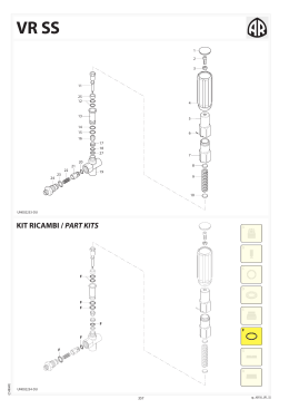
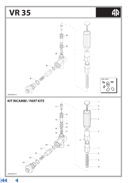
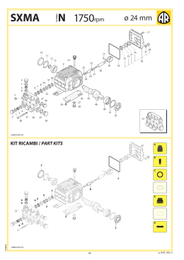
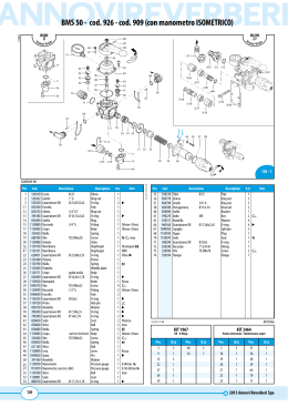
I
E
D
F
GARANZIA
I nostri prodotti sono garantiti per mesi
12 dalla consegna. La Ditta si assume la
responsabilità per tutti quei particolari
che presentassero difetti di materiale o di
lavorazione. Non è riconosciuta la garanzia
per cattiva manutenzione, anormale
impiego e per quelle parti non costruite
dalla Ditta. Le riparazioni dovranno essere
effettuate presso la fabbrica o da personale
autorizzato. Nello stesso istante in cui i
prodotti saranno manomessi da terzi, ogni
garanzia sarà ritenuta scaduta. Per ogni
verifica i prodotti dovranno essere inviati in
Porto Franco. Nel caso di effettiva necessità
di sostituzione di particolari sarà addebitato
il solo costo della mano d’opera. Per il vostro
fabbisogno di ricambi chiedete sempre
ricambi originali. In caso diverso non sarà
riconosciuta alcuna garanzia.
Numero per ordini telefonici:
(+39) 059.414.411
Numero per ordini con fax:
(+39) 059.253.505
GARANTÍA
Nuestros productos están garantizados
por 12 meses desde la fecha de la entrega.
Ninguna garantía será reconocida por malo
entretenimiento o por uso incorrecto de
los productos. Pidan siempre repuestos
originales. En caso contrario no se
reconocerá ninguna garantía.
GARANTIE
Die Firma gewährt eine Garantie von 12
Monaten, gerechnet vom Lieferdatum.
Zweckfremder Einsatz und/oder nachlässige
Wartung schließen jede Garantie aus. Im
Bedarfsfall immer Original-Ersatzteile von
der Firma anfordern. Anderenfalls kann
keine Garantie gewährt werden.
GARANTIE
Nos produits sont garantis pour 12 mois
à partir de la date de livraison. Aucune
garantie ne sera reconnue, suite au
mauvais entretien ou emploi anormal des
produits. Pour tous vos besoins de pièces de
rechange, demandez toujours les rechanges
originaux. Au contraire, aucune garantie ne
sera reconnue.
Our products are guaranteed for a period
of 12 months after the date of delivery.
Warranty will not be acknowledged if the
products are not used according to the
manufacturer’s instruction or are badly
maintained. Always ask for original Spareparts, otherwise warranty will not be
acknowledged.
GB WARRANTY
Lubrificare con GRASSO Molykote G807
Lubricate with Molykote G807 GREASE
Avvitare con Loctite 5331 (Bianca)
Screw down with Loctite 5331 (White)
Lubrificare con GRASSO Molykote PG54
Lubricate with Molykote PG54 GREASE
Lubrificare con GRASSO Molykote 1000
Lubricate with Molykote 1000 GREASE
Lubrificare con GRASSO P40
Lubricate with P40 GREASE
Coppia serraggio Tolleranza +0/-10% Nm
Tightening torque tolerance +0/-10% Nm
Lubrificare con OLIO MOTORE
Lubricate with ENGINE OIL
Lubrificare con GRASSO MINERALE
Lubricate with MINERAL GREASE
Montare con PRESSA
Assemble with PRESS
Montare a caldo con RISCALDATORE
Assemble hot with HEATER
Avvitare con Loxeal 83-21 Frenafiletti FORTE (Verde)
Screw down with Loxeal 83-21 STRONG (Green)
thread sealer
Avvitare con Loxeal 55-14 Frenafiletti MEDIO (Rosso)
Screw down with Loxeal 55-14 MEDIUM (Red) thread
sealer
Avvitare con Loxeal 24-18 Frenafiletti DEBOLE (Porpora)
Screw down with Loxeal 24-18 WEAK
(Purple) thread sealer
Incollare con Loctite 454
Glue with Loctite 454
Spruzzare un velo di Molykote D-321R Spray
Spray on a light coat of Molykote D-321R
Sigillare con Loxeal 59-10
Seal with Loxeal 59-10
Sigillare con Arexons Mastice
Seal with Arexons Filler
Sigillare con Arexons MOTORSIL D
Seal with Arexons MOTORSIL D
Incollare con Biadesivo acrilico VHB-3M 4945
Glue with VHB-3M 4945 acrylic biadhesive
Avvitare con Loctite 2701 Frenafiletti FORTE (Verde)
Screw down with Loxeal 83-21 STRONG (Green)
thread sealer
Prescrizioni per Montaggio
Prescription for Assembly
Member of
AT E N Ç Ã O :
ATTENZIONE:
AT TENTION:
ACHTUNG:
AT E N C I Ó N :
AT TENTION:
BY MATIC 50
200
l/min
52,8
gpm (US)
OUTPUT
DÉBIT
LEISTUNG
CAUDAL
PORTATA
50
bar
725
psi
PRESSURE
PRESSION
DRUCK
PRESIÓN
PRESSIONE
2 (+2)
N. VALVES
N. ROBINETS
N. VENTILEN
N. ROBINETS
N. RUBINETTI
This manual must be read before beginning installation of the unit.
Ce livret doit être lu avant d’installer et d’employer le produit.
Das vorliegende Handbuch ist vor der Installation und dem Gebrauch des Produkts aufmerksam zu lesen.
Este manual debe ser leído antes de proceder a la instalación Y uso del producto.
Este manual deve ser lido antes de proceder à la instalação e ao uso do producto.
Il presente libretto va letto prima di procedere all’installazione ed uso del prodotto.
CONTROL UNITS
GROUPES DE COMMANDE
BEDIENUNGSARMATUREN
GRUPOS DE MANDO
GRUPPI COMANDO
2,7
kg
WEIGHT
POIDS
GEWICHT
PESO
PESO
TECHNICAL DATA / DONNÉES TECHNIQUES / TECHNISCHE ANGABEN
CARACTERÍSTICAS TÉCNICAS / CARATTERISTICHE TECNICHE
- Control units for medium and high pressure pumps - Grupo de mando para bombas de media y alta presión
- Groupes de commande pour pompes moyennes et - Gruppi comando per pompe a media ed alta pressione
haute pression
- Bedienungsarmaturen für Mittel- und
BY MATIC 50
Hochdruckpumpen
Via M.L.King,3 - 41122 Modena (Italy)
Tel. (+39) 059.414.411 - Telefax (+39) 059.253.505
E - Mail Italia: [email protected]
E - Mail export: [email protected]
ANNOVI REVERBERI S.p.A.
cod. 99370-FR
Characteristics and descriptions are not binding. -Données descriptions et illustrations n’ engagement pas le constructeur. - Angaben, Beschreibungen, und illustrationen sind nicht
verbindlich. - Noticias y ilustraciones no son empeñativas. - Os dados, descrições e ilustrações são fornecidos a título informativo e não comprometem o fabricante. - Dati, descrizioni ed
illustrazioni sono forniti a titolo indicativo e non impegativo.
1158610
BY MATIC 50 cod. 960 - cod.905 (con manometro ISOMETRICO)
68
Vers
ione-Version
49
48
46
47
51
50
34
43
52
39
53
38
54
1
2
3
4
37
5
45
33
44
32
43
16
55
35
42
69
41
36
56
67
57
34
34
62
32
6
66
7
16
16
8
9
61
58
40
64
3
2
66
31
10
59
60
58
57
56
16
31
30
11
17
18 19 20
63
29
27
28
12
17
3
13
3
74
23
15
24
25
26
45
65
2-1
V
ne-Ve
ersio rsion
14
21 22
45
Pos
1
2
3
4
5
6
7
8
9
10
11
12
13
14
15
16
17
18
19
20
(CI 01.07.10 GO)
(1301)
21
22
23
24
25
26
27
28
29
30
31
32
33
34
35
36
37
38
39
40
41
42
43
Cod.
550370
550242
550350
780060
1150031
1150021
1150041
1150050
770590
1150060
850760
850750
390180
850490
850713
390060
1150012
320420
680700
1150070
1150130
1150131
620031
1150180
1150190
1150200
1150171
820490
1150921
1040370
1150140
1150150
1150161
160142
110130
1040690
1150251
1150120
850720
390340
740290
850650
850660
850680
Descrizione
Curva
Ø 25
Girello
1” G
Guarnizione OR
Ø 23,81X2,62
Vite
TCEI M6x25
Flangia
Disco
Guarnizione
Distanziale
Guarnizione OR
Ø 21,95x1,78
Sede
Forcella
Ghiera
3/4” G F
Guarnizione OR
Ø 18,72x2,62
Anello
Raccordo
1/2” G M
Guarnizione OR
Ø 20,63x2,62
Corpo
Molla
Vite
TCEI M6x20
Valvola
Membrana
Membrana
Guarnizione OR
Ø 25,80x3,53
Pistone
Molla
Piattello
Corpo
guida molla
Guarnizione OR
Ø 34,65x1,78
Manopola
Vite
TCEI M6x22
Raccordo
Morsetto
Corpo
rubinetto
Rubinetto
1/2” G M-M SX
Girello
1/2”
Forcella
Guarnizione OR
Ø 65x2
Perno
Rondella
Guarnizione OR
Ø 7,30x2,4
Guarnizione OR
Ø 14x1,78
Sede
Sfera
Molla
Description
Elbow
Ring nut
O-ring
Screw
Flange
Plate
Gasket
Spacer
O-ring
Seat
Fork
Ring nut
O-ring
Ring
Fitting
O-ring
Body
Spring
Screw
Valve
Diaphragm
Diaphragm
O-ring
Piston
Spring
Wobble plate
Body
O-ring
Knob
Screw
Fitting
Clamp
Body
Cock
Ring nut
Fork
O-ring
Hub pin
Washer
O-ring
O-ring
Seat
Ball
Spring
Q.ty
1
1
2
4
1
1
1
1
1
1
1
1
1
1
1
4
1
1
1
1
1
1
1
1
1
1
1
1
1
4
2
4
2
2
4
2
1
1
1
1
2
2
2
3
Note
C10
sp_bymatic50.pdf
SL000308-BU
Pos Cod.
Descrizione
Description Q.ty
superiore distributore Body
44 1150082 Corpo
1
45 320360 Vite
TCEI M8x22
Screw
6
46 850830 Molla
Spring
1
47 621160 Sfera
Ball
1
48 1150891 Leva
Lever
1
49 1040820 Spina
Pin
1
50 391460 Rondella
Washer
1
550545 Manometro
Pressure gauge
1
1151010 Manometro isometrico Ø63
Pressure gauge
1
52 1150100 Sfera
Ball
1
53 1150091 Sede
Seat
1
54 880270 Guarnizione OR
Ø 17,17x1,78
O-ring
1
55 550210 Tubo
Ø 25
Pipe
1
56 850770 Ghiera
Ring nut
2
57 850790 Girello
3/4” G
Ring nut
2
58 850780 Portagomma
Hose tail
2
59 180370 Vite
TE M8x25
Screw
2
60 850690 Staffa
Bracket
1
61 390270 Dado
M8
Nut
2
62 160141 Rubinetto
1/2” G M-M DX Cock
2
63 550331 Rondella
Washer
4
64 1150280 Guarnizione OR
Ø 50,52x1,78
O-ring
1
65 1150690 Raccordo
3/4” G F-F
Fitting
1
66 960160 Guarnizione OR
Ø 17,86x2,62
O-ring
2
67 1040950 Copiglia
Split pin
2
68 1150930 Tappo
Plug
1
69 1150840 Boccola
Bushing
1
74 550394 Flangia
Flange
1
Non compreso nel BY MATIC 50 - No part of BY MATIC 50
51
C10 Inox
Desmopan
NBR
Viton
Nera
C10
KIT 1967
Inox
C20
Nera
0-80 bar
0-50-80 bar
Inox
C20
KIT 1968
OR - O-Rings
Viton
Note
Pronto intervento - Maintenance repair
Pos.
Q.ty
Pos.
Q.ty
Pos.
Q.ty
Pos.
Q.ty
3
9
13
22
27
36
39
40
2
1
3
1
1
1
1
2
54
1
3
7
9
10
16
18
19
20
2
1
1
1
2
1
1
1
21
22
23
24
27
36
38 - 39
64
1
1
1
1
1
1
1
1
(CI GO 24.11.11)
MI 99370
BY MATIC 50 cod. 960 - cod.905 (con manometro ISOMETRICO)
Kit per/for BY MATIC 50
KIT 895 “I”
SL000070-EZ
KIT 988 “S”
KIT 999 “S”
UN000511-IB
UN000512-IB
KIT 990 “S”
KIT 997 “S”
UN000513-IB
UN000514-IB
Comando incorporato e separato - Build-in control unit and remote control
KIT 988 "S"
Pos.
Q.ty
1
2
3
74
1
1
1
1
Pos.
KIT 999 "S"
Comando separato
Remote control
Q.ty
Per / for AR 903 - AR 1053 - AR 1203
BHA/BHP 130 - 150 - 170 - 200
BHS 90 - 105 - 120 - 130 - 150 - 170 - 200
Pos.
Q.ty
2
3
55
1
1
1
Pos.
Q.ty
Per / for AR 713 - AR 813 - AR 1064 - AR 1516
AR 903 - AR 1053 - AR 1203
BHA/BHP 130 - 150 - 170 - 200
Pos.
Q.ty
2
3
55
59
60
61
1
1
1
2
1
2
KIT 997 "S"
Per / for AR 713 - AR 813 - AR 1064
AR 903 - AR 1053 - AR 1203
BHS/BHA/BHP 130 - 150 - 170 - 200
Pos.
Q.ty
2
3
55
56
57
58
1
1
1
2
2
2
59
60
61
66
2
1
2
2
Per / for AR 713 - AR 813 - AR 1064
AR 903 - AR 1053 - AR 1203
BHS/BHA/BHP 130 - 150 - 170 - 200
121,5
2
2
2
1
2
2
2
Q.ty
Ø 25
70
292,5
57
58
59
60
61
62
66
Pos.
10
9
10
117
187
50
70
10
101
1
1
1
2
2
2
4
1
2
316
Ø 3/4" G
1
2
3
16
32
33
34
55
56
Q.ty
400
290
156
Ø 13
9
Q.ty
40
Pos.
15
Q.ty
Pos.
Comando separato
Remote control
Per / for AR 713 - AR 813 - AR 1064
AR 903 - AR 1053 - AR 1203
BHS/BHA/BHP 130 - 150 - 170 - 200
Comando separato
Remote control
Pos.
KIT 990 "S"
Comando separato
Remote control
6
4
DI 1158504
KIT 895 "I"
Comando incorporato
Build in control
GB
F
MONTAGE
1.Monter solidement la bride (60).
2.Assembler les raccords rapides au tube HP de raccordement avec la
pompe, puis brancher BY MATIC 50 au refoulement de la pompe.
3.Raccorder le retour (55) directement à la citerne, sans étranglements.
4.Raccorder les tuyaux HP aux robinets en sortie.
DESCRIPTION ET MODE D’UTILISATION
L’unité de commande BY MATIC 50 règle la pression d’utilisation dans
la distribution du liquide d’arrosage.
Les chiffres rappelés dans le texte correspondent aux repères sur
l’éclaté. BY MATIC 50 est constituée d’un régulateur de pression à
membrane à tarage manuel par la poignée (28). Dans le corps principal du régulateur est incorporé un clapet de décharge rapide. La sortie
sous pression vers les utilisations est canalisée par deux collecteurs à 1
voie et, sur demande, à 2 voie pour un total de 4 voies.
ASSEMBLY
1.Firmly secure the mounting bracket (60).
2.Connect the quick couplings to the high pressure line from the
pump and then connect BY MATIC 50 to the pump outlet.
3.Connect the drain (55) to the tank directly, without flow restriction elements.
4.Connect the high pressure hoses to the outlet valves.
MODE D’UTILISATION
1.Suivre les instructions de fonctionnement de la pompe.
2.Contrôler les fuites éventuelles du circuit hydraulique à la hauteur
des jonctions et des raccords, en faisant circuler de l’eau.
3.Toutes les opérations sont commandées par le levier (48) dont les
fonctions sont représentées sur le schéma ci-dessous.
4.La poignée (28) règle la pression d’utilisation : une rotation dans
le sens des aiguilles d’une montre augmente la pression (+); une
rotation dans le sens contraire diminue la pression (-).
5.Laver l’unité de commande entièrement à l’eau après le travail. Veiller à éliminer toute stagnation des produits agressifs.
DESCRIPTION AND USE
The BY MATIC 50 control unit is designed for regulating working
pressure in the distribution of sprayed liquids.
Numbers refer to the exploded view of the unit. BY MATIC 50
comprises a pressure regulating diaphragm valve with a manual
adjustment knob (28). The main body is also equipped with a
rapid drain valve. The pressurised outlet is connected to the users
through two 1-way manifolds, which can be supplied in 2-way
versions on request to provide a total of 4 pressure lines.
USE
1.Refer to the pump user handbook.
2.Check for possible leaks in the hydraulic circuit from connections and unions by circulating water through the system.
3.All operations are controlled by a lever (48), the functions of
which are illu strated in the following diagram.
4.Use knob (28) to regulate working pressure: turn clockwise to
increase pressure (+), counterclockwise to decrease (-).
5.Flush the control unit with water when you finish work to remove any internal deposits of aggressive products.
SAFETY INSTRUCTIONS
This manual must be stored carefully. Read and follow the following safety instructions:
• Do not use the unit with flammable liquids, or liquids with
characteristics not compatible with the correct functioning of
the unit.
• The installation of the unit must be carried out by qualified staff.
INSTRUCTIONS DE SÉCURITÉ
Conserver ce manuel avec le plus grand soin. Lire et respecter les
instructions de sécurité ci-dessous:
• Ne pas utiliser le produit avec des fluides inflammables ou ayant
des caractéristiques incompatibles avec le fonctionnement correct du produit lui-même.
• L’installation du produit doit être effectuée par un personnel
qualifié.
D
BESCHREIBUNG UND GEBRAUCH
Das Steueraggregat BY MATIC 50 dient zur Einstellung des
Betriebsdruckes bei der Verteilung des Sprühmediums. Die in
Klammern angegebenen Zahlen beziehen sich auf die Explosionszeichnung des Produkts. BY MATIC 50 besteht aus einem Membran-Druckregelventil, das sich durch den Handgriff (28) manuell
einstellen läßt. Im gleichen Hauptkörper ist das Schnellablaßventil eingebaut. Die Druckweiterführung zu den Verbrauchern
erfolgt über zwei 1-Weg, auf Wunsch 2-Weg Sammelleitungen,
insgesamt über 4 Wege.
MONTAGE
1.Den Bügel (60) fest anbringen.
2.Die Schnellanschlüsse an die Hochdrucklei-tung zum Pumpenanschluß anbringen, danach BY MATIC 50 druckseitig an die
Pumpe anschließen.
3.Die Abflußleitung (55) direkt, ohne Drosselstellen, an den Tank
anschließen.
4.Die Hochdruckleitungen an die Ablaßventile anschließen.
GEBRAUCH
1.Siehe Betriebsanleitung der Pumpe.
2.Durch Wasserzirkulation überprüfen, ob im Hydraulikkreis an
den Anschlüssen bzw. Verbindungen Leckstellen bemerkbar
sind.
3.Sämtliche Betätigungen werden durch den Hebel (48) gesteuert, dessen Funktionen im u.a. Schema dargestellt sind.
4.Durch den Handgriff (28) läßt sich der Betriebsdruck einstellen.
Beim Drehen im Uhrzeigersinn wird der Druck erhöht (+), beim
Drehen gegen den Uhrzeigersinn verringert (-).
5.Nach dem Betrieb ist das Steueraggregat mit Wasser auszuspülen, um Rückstände aggressiver Produkte zu entfernen.
SICHERHEITSANLEITUNGEN
Vorliegendes Handbuch sorgfältig aufbewahren und folgende
Sicherheitsanleitungen aufmerksam lesen und beachten:
• Produkt nicht mit entzündbaren oder sonstigen Flüssigkeiten
verwenden, deren Eigenschaften mit einem einwandfreien
Betrieb des Produkts nicht vereinbar sind.
• Die Produktinstallation ist von qualifiziertem Fachpersonal vorzunehmen.
E
DESCRIPCIÓN Y MODO DE USO
El grupo de mando BY MATIC 50 sirve para regular la presión de
trabajo en la distribución de líquido para pulverización.
Las indicaciones numéricas se refieren al gráfico de despiece
del producto. BY MATIC 50 está compuesto por una válvula de
regulación de la presión a membrana, que se calibra manualmente con la perilla (28). En el cuerpo principal hay una válvula
de descarga rápida. La salida a presión está canalizada por dos
colectores de 1 vía; a pedido se suministran colectores de 2 vías
para un total de 4 vías.
MONTAJE
1.Montar el soporte firmemente (60).
2.Ensamblar los rácores rápidos al tubo de alta presión de conexión con la bomba y, luego, conectar BY MATIC 50 al conducto
de impulsión de la bomba.
3.Conectar directamente la descarga (55) a la cisterna, sin producir obstrucciones.
4.Conectar los tubos de alta presión a los grifos en salida.
MODO DE USO
1.Remitirse a las instrucciones operativas de la bomba.
2.Controlar, haciendo circular el agua, que no haya pérdidas ni en
las juntas y ni en los rácores del circuito hidráulico.
3.Todas las operaciones se mandan mediante la palanca (48), cuyas
funciones están representadas en el esquema ilustrado más adelante.
4.Mediante la perilla (28) se regula la presión de trabajo: girándola
en el sentido de las manecillas del reloj, aumenta la presión (+), y
en sentido contrario al de las manecillas del reloj, disminuye (-).
5.Después del trabajo, lavar internamente con agua el grupo de
mando y quitar eventuales restos de productos agresivos.
LEVER POSITION
POSITIONS LEVIER
HEBELPOSITIONEN
POSICIÓN PALANCA
POSIZIONI LEVA
INSTRUCCIONES PARA LA SEGURIDAD
Es necesario conservar con cuidado el presente manual, leer y
respetar las siguientes instrucciones para la seguridad:
• No utilizar el producto con fluidos inflamables o que tengan
características no compatibles con el correcto funcionamiento
del producto.
• La instalación del producto debe ser efectuada por personal
especializado.
I
DESCRIZIONE E MODO D’USO
Il gruppo comando BY MATIC 50 serve per la regolazione della
pressione di lavoro nella distribuzione del liquido per irrorazione.
I richiami numerici fanno riferimento al disegno esploso del
prodotto. BY MATIC 50 è composto da una valvola di regolazione
della pressione a membrana, tarabile manualmente attraverso
la manopola (28). Nello stesso corpo principale vi è inserita la
valvola di scarico rapida. L’uscita in pressione agli utilizzi è canalizzata da due collettori a 1 via, a richiesta a 2 vie per un totale
di 4 vie.
MONTAGGIO
1.Montare saldamente la staffa (60).
2.Assemblare i raccordi rapidi al tubo alta pressione di collegamento con la pompa, quindi collegare BY MATIC 50 alla mandata della pompa.
3.Collegare lo scarico (55) alla cisterna, senza strozzature, direttamente.
4.Collegare i tubi alta pressione ai rubinetti in uscita.
MODALITÀ D’USO
1.Fare riferimento alle istruzioni operative della pompa.
2.Controllare facendo circolare acqua, eventuali perdite del circuito idraulico nelle giunzioni e nei raccordi.
3.Tutte le operazioni sono comandate dalla leva (48) le cui funzioni sono rappresentate nello schema sotto riportato.
4.Mediante la manopola (28) si regola la pressione di lavoro:
in senso orario aumenta la pressione (+), in senso antiorario
diminuisce (-).
5.Lavare il gruppo comando internamente con acqua dopo il
lavoro, togliendo eventuali ristagni di prodotti aggressivi.
ISTRUZIONI PER LA SICUREZZA
È necessario conservare con cura il presente manuale, leggere e
rispettare le seguenti istruzioni per la sicurezza:
• Non utilizzare il prodotto con fluidi infiammabili o aventi caratteristiche non compatibili con il corretto funzionamento del
prodotto stesso.
• L’istallazione del prodotto deve essere effettuata da personale
qualificato.
Scarica