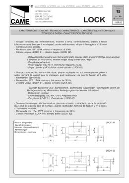
PORTE AUTOMATICHE
|
AUTOMATIC DOORS
ELETTROBLOCCO
ELECTRIC LOCK
DISPOSITIF DE BLOCAGE
ELEKTROSPERRE
BLOQUE ELECTRICO
|
PORTES AUTOMATIQUES
|
AUTOMATISCHE TÜREN
|
PUERTAS AUTOMATICAS
Documentazione
Tecnica
M73
MA 7012
rev
rev.. 1.1
© CAME 12/98
119PM73
Dispositivo elettromeccanico per il blocco delle ante,
integrabile ai sistemi CORSA E RODEO.
Electromechanical gate
wing lock for installation
on CORSA and RODEO
system.
Dispositif électromécaniques pour le blocage des
portes pouvant être installé
sur les systèmes CORSA et
RODEO.
Electromechanische
Vorrichtung zur Blockierung
von Torflügeln, die in die
Antriebssysteme CORSA
und RODEO (ein oder
zweiflügelige
Tore)
eingebaut werden kann.
Dispositivo electromecánico para el bloqueo de
las puertas, integrable con
los sistemas
CORSA y
RODEO.
CARATTERISTICHE
TECNICHE:
TECHNICAL
SPECIFICATIONS:
CARACTERISTIQUES
TECHNIQUES:
TECHNISCHE DATEN:
CARACTERISTICAS
TECNICAS:
Alimentazione: 24V d.c.
(tramite ZP7/ZP8);
Assorbimento: 1,6A;
Servizio : Intermittente 50%.
Alimentation: 24V d.c.
(from ZP7/ZP8);
Current draw: 1,6A;
Service : Intermittent 50%.
Alimentation: 24V d.c.
(par ZP7/ZP8);
Absorption : 1,6A;
Service : Intermittent 50%.
L'apparecchiatura è completa di :
- Elettroblocco;
- Cordino per lo sblocco
manuale a distanza;
- Cavo di alimentazione;
- Staffa di aggancio.
The package includes the
following equipment:
- Electric lock unit;
- Cord for remote manual
release of lock;
- Power cable;
- Locking bracket.
L'appareillage comprend : Das Gerät ist ausgestattet
mit :
- Dispositif de blocage
- Elektrosperre;
électromecaniques;
- Drahtseil zur Fern- Câble pour le
Handentriegelung;
dèblocage à distance;
- Natzanschlußkabel;
- Câble d'alimentation;
- Befestigungsbügel.
- Etrier de fixation.
Versorgungsspannung:
24V Gleichstrom
(über ZP7/ZP8);
Stromaufnahme: 1,6A;
Betrieb : intermittierend 50%.
Alimentación: 24V d.c.
(mediante ZP7/ZP8);
Absorción: 1,6A;
Servicio : Intermitente 50%.
El aparato está dotado
de :
- Bloque eléctrico;
- Cuerda para el
desbloqueo manual a
distancia;
- Cable de alimentación;
- Estribo de enganche.
1
1) Morsettiera
2) Ancoraggio superiore
3) Cordino di sblocco
4) Perno blocco
5) Registro cavetto
6) Ancoraggio anteriore
7) Viti UNI5931 M5 x12
8) Morsetto aggancio
sblocco
9) Staffa di aggancio
10) Cavo alimentazione
4 x 0,5
1) Terminal board
2) Upper attachment
3) Release cord
4) Lock pin
5) Tension adjuster for cord
6) Front attachment
7) Screws UNI5931 M5 x12
8) Clamp for connecting
release knob
9) Connecting bracket
10) 4 x 0,5 Power cord
1) Plaque á bornes
2) Fixation supérieure
3) Cable de déblocage
4) Pivot de blocage
5) Réglage du câble
6) Fixation antérieure
7) Vis UNI5931 M5 x12
8) Serre-câble fixation
déblocage
9) Etrier de fixation
10) Câble d'alimentation
4 x 0,5
1) Klemmenbrett
2) Obere Verankerung
3) Entriegelungsseil
4) Sperrbolzen
5) Kabel-Stellschraube
6) Frontverankerung
7) Schrauben UNI5931
M5 x12
8) Etrigelungsseil
9) Befestigungsbügel
10) Kabelstromversorgung
4 x 0,5
1) Caja de borne
2) Anclaje superior
3) Cuerda de desbloqueo
4) Pernio bloqueo
5) Regístro caveto
6) Anclaje anterior
7) Tornillos UNI5931
M5 x12
8) Caja de borne
enganche desbloqueo
9) Estribo de enganche
10) Cable alimentación
4 x 0,5
MONTAGGIO - INSTALLATION - MONTAGE - MONTAGE - MONTAJE
2
A n t a s i n g o l a a p e r t a a s i n i st r a
S ingle gate wing o pen to the left
P o r t e u n iq u e o u v e r t e a g a u c h e
Ein flügelig es to r, rechtsschließend
P u e r t a i n d i v i d u a l a b i e r ta a i z d a
C a rr
rree l lo l ib e r o c on st a ff a d i a gg a n c io
Free trolley with locking bracket
C h a r i o t li b r e ave c é t r i e r de fi x at i o n
Freier Laufschlitten mit Befestigungsbügel
C a rr
rree t e li br e c on e s t r i b o d e en
e n g an c h e
Ap e rtura
Aperture
O u v e rture
Öffnungsweiten
Ap e rtura
A n t a s i n g o l a a p e r t a a d e s t ra
S ingle gate wing o pen to the right
P o r t e u n i q u e o u v e r t e a d ro i te
Ein flügelig es to r, rechtsschließend
P u e r t a i n d i v i d u a l a b i e r ta a d c h a
C a rr
rree l lo c o ll
llee g a t o a ll 'a t t a c c o i n f er i o r e
Trolley connected to lower belt attachment flange
C h ar i o t r eli
liéé à l' é t r ie r i n fé r i e u r
Mit dem unteren Antriebsriemen-Flansch verbund ener Laufschlitten
C a rr
rree t e c on ec t a d o a l en ga n c h e i n fe r i o r
Ap e rtura
Aperture
O u v e rture
Öffnungsweiten
Ap e rtura
D o p p i a an
an t a
Double g ate wing
p or t e d o u b l e
Zweiflügelig es tor
D o bl e pu e r ta
C a rr
rree l lo l ib e r o
Free trolley
C h a r i o t li
lib
br e
Freier Laufschlitten
C a rr
rree t e li b r e
Ap e rtura
Aperture
O u v e rture
Öffnungsweiten
Ap e rtura
Ap e rtura
Aperture
O u v e rture
Öffnungsweiten
Ap e rtura
C a rr
rree l lo c o ll
llee ga t o a ll 'at t a c c o s u p e r i or e
Trolley connected to upper b elt atta chment flange
C h ar i o t r eli
liéé à l' é t r ie r s u p ér i eu r
Mit dem ob eren Antrieb sriemen-Flansch verbundener Laufschlitten
C a rr
rree t e c on ec t a do a l en ga n c h e s u p er io r
2
APPLICAZIONE - INSTALLATION - APPLICATION - ANBRINGUNG - APPLICACION
1) Installare la staffa di aggancio (9) mediante le viti
in dotazione (8) (Fig.1) sul
carrello libero (Fig. 2). La
staffa di fissaggio è
regolabile in altezza per
consentire una chiusura
ottimale .
* Il carrello libero su cui
fissare la staffa va scelto in
relazione alla posizione di
porta aperta (Fig. 2);
1) The locking bracket (9) is
installed onto the free trolley
which is to be locked into
place. The screws supplied
with the unit (8) are used to
install the bracket, as shown in
design 2.
The height of the bracket
can be adjusted to obtain
perfect locking.
* The trolley is chosen
according to the position of
the door when open; follow
2)
Predisporre the diagram on designers 2;
l'elettroblocco sul profilo di
supporto dell'automazione 2) Position the electric lock
allineando il perno unit on the support profile
dichiusura dell'elettro-bloc- of the automation system
co (Part.A Fig.3) con il foro while aling the lock pin (Det.
ad asola della staffa di ag- A; Des.3 ) with the slot in the
gancio.
locking bracket .
Regolare la posizione del Adjust the position of the
dispositivo in modo che il unit so that the lock pin
perno non interferisca con enters the locking bracket
la staffa di aggancio du- smoothly
and
no
rante il funzionamento mechanical interference
(Fig.3).
occurs when the lock is
N.B.: operazione da effet- opened : see design 3 on.
tuare con anta/e chiusa/e. This operation must be
performed with wing/s
closed).
ATTENZIONE: le operazioni di collegamento elettrico
devono essere effettuate
dopo aver disinserito la tensione di linea e l'eventuale
batteria del SISTEMA ANTIPANICO MA7032.
ATTENTION: this operation
must be performed ONLY
after disconnecting the line
voltage and the battery on
theELECTRICAL ANTIPANIC
SYSTEM MA7032 (if
installed).
1) IInstaller
nstaller l'étrier de fixation
sur le chariot libre à bloquer
en utilisant les vis fournies
avec le matériel, de la façon
raprésentée sur le schéma2.
L'étrier de fixation est
réglable en hauter afin de
permettre une fermeture
optimale.
* La choix du chariot doit être
fait par rapport à la position
"porte ouverte", en respectant
les schémas 2;
2) Placer le dispositif de
blocage électromé-canique
sur le profil de support de
l'automatisme, en alignat
le pivot (Det.A;Sch.3) de
fermeture
avec
la
boutonnière présente sur
l'étrier de fixation.
Régler la position du
dispositif de façon à ce que
le pivot de fermeture entre
parfaitement dans l'étrier de
fixation sans qu'il gêne
l'étrier dans la phase d'ouverture (schéma 3).
Cette opération doit être
effectuée avec la/les porte/
s fermée/s.
ATTENTION:
cette
opération doit être effectuée
UNIQUEMENT après avoir
interrompu la tension de
ligne et après avoir
débranché la batterie de
l'éventuel
SYSTEME
A N T I P A N I Q U E
ELECTRIQUE MA7032.
Staffa di aggancio
Locking bracket
Etrier de fixation
Befestigungsbügel
Estribo de enganche
3
1) Den Befestigungsbügel
am freien Laufschlitten,
gemäß Abb. 2, mit den zum
Lieferumfang gehörenden
Schrauben befestigen.
* Der Befestigungsbügelist
höhenverstellbar, um eine
optimale Türschließung zu
ermöglichen.
Hinweis:
Der
freie
Laufschlitten, auf dem der
Bügel zu befestigen ist, ist
der Position der frei Tür
entsprechend zu wählen 2;
2) Die Elektrosperre auf dem
Antriebs-Trägerprofil
positionieren und den
Sperrbolzen (Detail A, Abb.
3) der Elektrosperre mit der
Schlitzöffnung
des
Befestigungsbügels
ausrichten, daß sich
Sperrbolzen
und
Befestigungsbügel in der
Öffnungsphase
nicht
behindern (Abb. 3).
HINVEIS: dieser Vorgang ist
bei geschlossenem(n)
Torflügel(n) auszuführen.
ACHTUNG: Vor Ausführen
des
elektrischen
Anschlusses
die
Netzspannung und die Batterie des elektrischen
ANTIPANIK-SYSTEMS
MA7032.
(wenn
vorhanden) abtrennen.
1) Instalar el estribo de
enganche en el carrete libre
mediante los tornillos
suministrados
como
indicado en Fig. 2. La altura del estribo de anclaje se
puede regular para permitir
un cierre perfecto.
* Elagir el carrete libre en el
cual se fija el estribo en
relación a la posición de
puerta abierta (Fig. 2);
2) Predisponer el bloque
eléctrico en el perfil de
soporte
de
la
automatización alineando
el perno de cierre del
bloque eléctrico (Det. A Fig.
3) con el agijero a ojal del
estribo de enganche.
Ajustar la posición del dispositivo de manera que el
perno no interfiera con el
estribo de enganche en la
fase de apertura (Fig. 3).
NOTA: operación a
efectuarse con puerta/s
cerrada/s.
ATENCION:
las
operaciones de conexión
eléctrica deben efectuarse
después de desconectar la
tensión de linea y la eventual
batería del SISTEMA ANTIPANICO MA7032.
4
Perno di chisura
Lock pin
Pivot de fermeture
Sperrbolzen
Perno de cierre
Elettroblocco
Electric lock
Disp. de blocag
blocage
Elektrosperre
Bloque eléctrico
A
Viti
Screws
Vis
Schrauben
Tornillos
Staffa di aggancio
Locking bracket
Etrier de fixation
Befestigungsbügel
Estribo de enganche
3
3) Procedere con il collegamento del cordino di
sblocco come da Fig. 5.
Si consiglia un'applicazione lineare del cordino
evitando curvature accentuate.
3) To connect the manual
release cord, follow the
indications on design 5.
Lay the cord in a straight
line. Do not make tight
curves in the cord.
3) Pour le raccordement de
la cordelette de déblocage
manuel,
suivre
les
indications reportées sur le
schéma 5.
Il est conseillé de prevoir un
parcous droit pour la
cordelette en évitant par
conséquemment
les
courbures accentués.
3)
Das
Handentriegelungsseil,
gemaß Abb. 5, installieren
und dabei darauf achten,
daß es gerade und ohne
starke
Krümmungen
verlaüft.
3) PProceder
roceder con la conexión
de la cuerda de desbloqueo
como indicado en la Fig.5.
Se aconseja una aplicación
en línea de la cuerda evitando curvas acentuadas.
Fig. 4
5
Cordino di sblocco
Release cord
Câble de déblocage
Entriegelungsseil
Cuerda de desbloqueo
61 mm
mm..
Inserire il cordino in sede e bloccarlo tramite l'apposito morsetto con chiave a tubo da 6 mm., quindi regolare
la tensione del cavo.
Insert the the cord into its seat and use a 6 mm. socket wrench to tighten the cord down. Then, adjust the tension
on the cord.
Introduire la câble dans son logement et la bloquer à l'aide du serre-câble prévu à cet effet avec une clé en
tube de 6 mm., puis régler la tension du câble.
Das Entriegelungsseil einfügen und am seinem Sitz mit der entsprechenden Klemmschraube und einem 6-mm.Steckschlüssel festmachen. Die Spannung des Kabels regulieren.
Introducir la cuerda en el alojamiento y bloquearla mediante la mordaza correspondiente con llave a tubo de
6 mm, posteriormente regular la tensión del cable.
Tutti i dati riportati nel presente libretto sono
indicativi. La CAME s.p.a. si riserva di apportare
eventuali modifiche inerenti all'evoluzione tecnologica dei prodotti.
All data mentioned in the present booklet are for
information only. CAME SPA reserves the right to
introduce changes relating to technological
improvements of the products.
CAME S.P.A.
Toutes les données mentionnées dans le livret
sont indicatives. CAME se réserve le droit
d'apporter des modifications éventuelles par
rapport à l'évolution téchnologique des produits.
ITALIA
VIA MARTIRI DELLA LIBERTÀ, 15
31030 DOSSON DI CASIER
TREVISO
CAME SUD S.R.L.
28045 MADRID
ITALIA CAME GMBH
7 RUE DES HARAS
92737 NANTERRE CEDEX
PARIS
DEUTSCHLAND
BERGSTRASSE, 17/1
70825 K ORNTAL
STUTTGART
FRANCE
CAME GMBH
AKAZIENSTRASSE , 9
16356 SEEFELD
BERLIN
Todos los datos de este libreto son indicativos.
CAME s.p.a. se reserva el derecho de aportar las
modificaciones producidas por la evolución
tecnológica de los productos.
ESPAÑA
C/JUAN DE MARIANA, 17
VIA F ERRANTE IMPARATO , 198
CM2 LOTTO A/7
80146 NAPOLI
CAME FRANCE S.A.
CAME AUTOMATISMOS S.A.
Alle in der vorliegenden Beschreibung
angegebenen Daten dienen nur der information.
CAME S.P.A. behält sich technische Andernungen
vor.
internet
www.came.it
e-mail
[email protected]
N° 12 100 8953
DEUTSCHLAND
Scarica