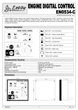
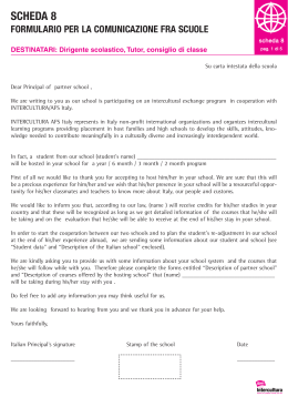
HPS 844
2,4 GHZ
USER MANUAL
CANBUSLINE
Thank you for choosing one of our product
HPS 844 rev. 03 June 2012 pag. 1 di 16
Universal CAN BUS alarm system
Nca Service introduces the new line of Can Bus alarms, HPS 844, which can be interfaced to the
vehicle’s original remote control through the CAN BUS (Controller Area Network).
This technology allows a fast and easy installation, as well as a bigger security of the system.
The HPS 844 is a UNIVERSAL antitheft device, compatible with a great number of vehicles ( see
the vehicle compatible list below).
You can easily select the vehicle at the moment of installation by positioning the
selector of the antitheft device (look at the picture).
To select the vehicle look at the
SELETTORE
vehicle compatible list
This article can operate (arm/disarm the system) with the original remote control of the car or with an
alarm remote control (OPTIONAL); in this way, it’s possible to fit the HPS 844 to a vehicle not
equipped with the CAN BUS technology. It is possible to memorize some 2,4 GHz ISM wireless
transmitters.
Selection
HPS 844
1
2
3
4
5
6
7
8
9
Selected Vehicle
Vehicle without CAN-BUS
Fiat Ducato 2006-2011 Euro 4 – Iveco Daily 2006-2011 Euro 4
Mercedes Sprinter 2006> – Mercedes Viano 2004> –
Volkswagen Crafter 2006> Version Siren
Volkswagen Transporter T5 2004-2009
Ford Transit 2006>
Mercedes Sprinter 2006> – Mercedes Viano 2004> –
Volkswagen Crafter 2006> Version Clacson CAN
Volkswagen Transporter T5 2010>
Renault Master 2010>
Fiat Ducato 2011> Euro 5 – Iveco Daily 2011> Euro 5
HPS 844 rev. 03 June 2012 pag. 2 di 16
General connection diagram HPS 844
There is a specific fitting instruction for every vehicle.The following diagram shows a general
connection example.
CONNECTOR A
SELECTOR
24
13
12
11
CONNECTOR A
RED Pos. 14
POSITIVE FIXED
BLACK Pos. 2
POSITIVE FIXED
NEGATIVE FIXED
WHITE/BROWN Pos. 22
CAN BUS
WHITE/GREEN Pos. 23
CAN BUS
ORANGE Pos. 14
Predisposition Volumetric Module
BROWN pos.7
NEGATIVE FIXED
MODULE
INPUT
PINK pos.15
Botton
Anti-Theft
GREEN/YELLOW Pos. 19
HAZARD
WHITE/BLUE pos. 5
GAS ALARM
UNLOCK
ANTI-tHEFT
GREY/BLACK pos.7
NEGATIVE INPUT
GREEN Pos. 21
ENGINE BLOCK
GREEN Pos. 24
max 10Amp
COMMAND COMFORT
MAX 100mA
1° ALARM
NEGATIVE INPUT
2° ALARM
POSITIVE INPUT
NEGATIVE
FOR BOTTON
POSITIVE FIXED
BROWN/BLACK Pos. 8
BLACK pos. 2
RED Pos. 14
BLACK Pos. 10
BLUE Pos. 4
BLUE/RED Pos. 12
RED Pos. 14
GREEN/BLACK Pos. 11
POSITIVE FIXED
POSITIVE KEY
BLACK Pos. 2
ARROW
YELLOW pos 13
NEGATIVE FIXED
BLUE/BLACK pos.3
YELLOWpos 17
ARROW
BONNET BUTTON
WHITE pos. 18
WHITE/RED pos. 1
OUTPUT
IN ALARM
COMMAND CLOSING
Predisposition Led
COMMAND LED
OUTPUT ALARM
YELLOW/BLUE pos. 9
DOORS
PURPLE pos. 20
COMMAND OPENING
DOORS
HPS 844 rev. 03 June 2012 pag. 3 di 16
Predisposition Siren
Self powered siren installation
The siren must be installed into the engine compartment, it is equipped with internal battery that
permit to the siren to sound when the power supply wires are cut.
Magnetic sensors 2.4 GHz installation
It is possible to install the 2,4 GHz transmitters on door and windows.
Put the transmitter on the fixed part and the magnet on the mobile part (door or windows), as showed
in the picture.
ATTENTION: the transmitters are equipped with an anti-tampering
system, please respect the minimum and maximum distance that are
showed in the picture. If the distance between these two devices is
too small, it is possible that there is a continuous alarm signal
transmission, this means continuous false alarms.
BATTERY REPLACEMENT: Open the box transmitter, extract the
PCB, take out the old battery and insert the new. Respect the polarity
that is showed on the battery seat. Use the lithium battery CR 20-32.
It is recommended to replace the battery every 2 or 3 years.
HPS 844 rev. 03 June 2012 pag. 4 di 16
Function of Magnetic Sensor
Every time that the Magnetic Sensor and Remote Control will be used, the alarm gives an answer
signal of aknowledgement, that shows the device recognition to stop the signal transmission. The
transmission is bidirectional.
It is showed by LED signalization:
- Fixed : the transmission is good, the transmitter is recognized;
- Fast flashing: the transmission is not good, too much distance from the alarm system, or sensor
is not memorized;
- 4 slowly flashing: battery discharged.
Memorizing of the magnetic sensors
The magnetic sensors can be memorized in two different areas.
• Magnetic sensors memorizing area 1 (not excludible by the NCA remote control)
- Push the anti hi-theft push-button 3 times, the LED flashes fast;
- During the LED flashing turn ON the magnetic sensor to memorize;
- The correct memorize is indicated by a bip, a flash lamp and the 1 second LED ON.
Repeat the procedure for each magnetic sensor to memorize.
The procedure can stop after 30 seconds from the last memorization or after turning ON the key.
The maximum number of the devices accepted in the area 1 is 24.
• Magnetic sensors memorizing area 2 (excludible by the NCA remote control)
This procedure is equal to the previous described for the magnetic sensor memorized in the area 1,
but in this case, the anti hi-theft push button must be pushed 4 times.
The maximum number of devices accepted in the area 2 is 8.
Memorizing of the NCA remote controls
Memorizing procedure:
- Push the anti hi-theft push button 5 times, the LED flashes fast;
- During the LED flashing push a NCA remote control button;
- The correct memorize is indicated by a bip, a flash lamp and the 1 second LED ON.
To memorize another NCA remote control, sequentially push the button of these, after the first
memorize, the second, etc..
The procedure can stops after 30 seconds from the last memorize, after the memorizing of the
maximum remote controls number accepted or after turn ON the key.
The maximum number of the remote controls accepted is 4.
HPS 844 rev. 03 June 2012 pag. 5 di 16
Original remote control operating
The alarm function through the original remote control is possible only on
vehicles that use the signal of the remote control by Can-Bus line.
SYSTEM ARMING
Push the lock button of the OEM. The arming will be confirmed by:
• 1 bip;
• The LED on the dashboard turn ON;
• Engine block ON (if connected):
• Modules output arming (Windows module, ultrasonic, etc.)
SYSTEM DISARMING
Push the unlock button of the OEM. The disarming will be confirmed by:
• 2 bip;
• The LED on the dashboard turn OFF;
• Engine block OFF (if connected)
• Modules output disarming (ultrasonic, etc..)
HPS 844 rev. 03 June 2012 pag. 6 di 16
NCA remote control operating (optional)
With NCA remote control, it’s possible to simulate the same original remote
control operation with some plus functions.
SYSTEM ARMING:
Push the button N°3 of the NCA remote control. Arming:
- 1 bip
- The LED on the dashboard turn ON;
- CDL locking (if connected)
- Engine block ON (if connected)
- Modules output arming (windows module, ultrasonic, etc..)
SYSTEM DISARMING
Push the button N°1 of the NCA remote control. Disarming:
- 2 bip
- The LED on the dashboard turn OFF;
- CDL unlocking (if connected);
- Engine block OFF (if connected);
- Modules output disarming (ultrasonic, etc..)
Neutral time and alert status
Once the signalling of arming is over, the alarm will stay for 10 seconds in “neutral time” condition,
signalled by the fixed light of the LED. The flashing of the LED of the dashboard will indicate that the
system supervises the vehicle and is ready to signal the alarms.
Alarm cause during the neutral time
If the alarm system notes a cause of alarm during the neutral time of 10 seconds, it is shown through
the blinker flashing (the number of the blinker flashing indicates the cause of alarm, as shown in the
table in the chapter “alarm memory”). If the alarm notes the same cause of alarm for 3 times, it gives
HPS 844 rev. 03 June 2012 pag. 7 di 16
an alarm cycle.
Alarm
In case of attempt to brake in, the system will emit an optic-acoustic signal (flashing of the blinkers
and sound of the siren), repeated for 30 seconds.
To stop the alarm signal without disarming, press the LOCKING button of the original remote control
or the button N°2 of the NCA remote control.
To stop the alarm signal and disarming, press the OPENING button of the original remote control or
the button N°1 of the NCA remote control.
Panic alarm
Alarm armed , 10 second after arming, press the LOCKING push- button of the original remote control
or the button N° 2 of the NCA remote control: central unit will do an alarm cycle of about 30
seconds.
To stop the alarm cycle press again the LOCKING push- button of the original remote control or the
button N° 2 of the NCA remote control.
It is possible to exclude the PANIC function, look at the list “PROGRAMMABLE FUNCTION”.
Volumetric module (HPA 55) exclusion
After the system arming, press the LOCKING push-button of the original remote control or the button
N°3 of the NCA remote control within 5 seconds. The exclusion will be confirmed by 3 bip and 3
blinkers flashes. Or press the close button on the original remote control, within 5 seconds, press the
open button on the original remote control, within 5 seconds press the close
button on the original remote control.
Adjustement ultrasonic module
Ultrasonic sensitivity may be adjusted by using the trimmer in the
module. Rotate the trimmer clockwise to increase sensitivity and anti
clockwise to decrease it. Warning: an incorrect adjustment may cause
false triggering of the alarm.
Ultrasonic Adjustement
HPS 55
Siren exclusion
Through the ignition key it is possible to exclude the functioning of the horn or the siren.
HPS 844 rev. 03 June 2012 pag. 8 di 16
With the alarm disarmed (CDL opened), turn on and off the ignition key for 3 times and, within 30
seconds, press the original remote control to close the CDL of the vehicle.
At the insertion of the antitheft and within the neutral time of 10 seconds press the key 2 of the NCA
remote control.
From this moment, the central unit will signal the attempt to break in by the flashing of the blinkers
only.
Exclusion magnetic sensor area 2
Function can only be activated by remote control NCA. Pushing contemporaneously the buttons N°1
and N°2, when the alarm is armed, during the neutral time, the magnetic sensor memorized in area 2
are excluded (look at the chapter “magnetic sensor memorizing).
Central door locking command
With this function it’s possible to control if the vehicle is closed.
Contemporaneously press the button N°3 and N°1, if the vehicle is closed the LED of the NCA
remote control flash for some seconds, but if the LED stay OFF it means that the vehicle is not closed.
ATTENTION: this function is able only if the vehicle was closed trough the NCA remote control.
Low battery NCA remote control
If during the system arming and disarming by the NCA remote control it doesn’t give the
acoustic signal means that the battery is discharged. This function is available if the base settings
about the bip on arming and disarming was not modified (look at the programming list)
BATTERY REPLACEMENT: Open the remote control box, extract the old battery and insert the new
one. Respect the polarity that is showed on the battery seat. Use the lithium battery CR 20-32.
It’s recommended to replace the battery every 2 or 3 years.
Jamming function
If the alarm system notes some radio disorders, it gives an alarm cycle.
Alarm memory
If the central unit records one or more causes of alarm, they are signaled, when disarming and open
the driver door or press the anti hi-theft push-button through the LED. To verify the type of alarm,
check the number of flashings of the LED with the list below.
HPS 844 rev. 03 June 2012 pag. 9 di 16
CAUSE
LED flashings
1
DOOR OPENING (SIGNALED BY CAN-BUS)
2
CDL
3
BONNET OPENING (SIGNALED BY CAN-BUS)
4
TRUNK OPENING (SIGNALED BY CAN-BUS)
5
KEY ON
7
ALARM BY INTERNAL PROTECTION
8
ALARM BY ADDITIONAL
INPUT (FILO BLU)
9
ALARM BY ADDITIONAL
INPUT (BLUE/RED WIRE)
OPENING (SIGNALED BY
CAN-BUS)
PROTECTION (SIGNALED BY
CAN-BUS)
12
ALARM BY TRANSMITTER
13
ALARM BY BONNET (NOT BY CAN BUS)
14
ALARM BY GAS
15
ALARM BY RADIO DISORDERS
DETECTOR
Programmable functions
It is possible to modify the function written in the list.
Alarm disarmed, press the anti hi-jack push-button as many times as the number of the function to
program.
The function programming is confirmed by 1 bip, 1 blinkers flash and 1 second LED ON.
The double functions (ON/OFF) are default set as OFF, making the programming the function turn ON,
and making again the programming, the function turn OFF, as the default setting.
N° Pression
FUNCTIONS
3
Area 1 transmitter memorizing
4
Area 2 transmitter memorizing
HPS 844 rev. 03 June 2012 pag. 10 di 16
5
NCA remote control memorizing
6
Set mode HORN/SIREN during the alarm cycle (SIREN default)
7
Set bip arm/disarm OFF/ON (bip ON default)
8
Set siren sound by relay (if it is CAN BUS in the parameters)
9
Set blinkers flashing by relay (if it is CAN BUS or PLX in the parameters)
10
Anti Aggression ON/OFF (OFF default)
11
Anti hi-theft ON/OFF (OFF default)
12
Set 30 seconds/1 second locking pulse (1sec default)
13
Set double/single locking pulse (single default)
14
15
16
17
18
19
20
Set double/single unlocking pulse (single default)
Set the blinker flashing, when arming/disarming the system by the
NCA remote control, ON/OFF (OFF default)
Anti distraction ON/OFF (OFF default)
Disarm alarm with the third button of the original remote control
ON/OFF (OFF default)
Panic alarm ON/OFF (ON default)
Bip for ultrasonic-comfort-siren-area 2 transmitter exclusion ON/OFF.
(ON default)
Intermittent engine block for the anti aggression and anti hi-theft
function ON/OFF (OFF default)
21
Fixed alarm output (WHITE wire) ON/OFF (OFF default)
22
Intermittent alarm output (WHITE wire) ON/OFF (OFF default)
23
Jamming function ON/OFF (ON default)
24
Original remote control operation ON/OFF (ON default)
25
Comfort permanent ON/OFF (OFF default)
HPS 844 rev. 03 June 2012 pag. 11 di 16
26
Alarm switch-off with the original remote control framework ON/OFF
(OFF default)
28
Radio device receiver ON/OFF (ON default)
29
NCA remote control deletion
30
Transmitter (area 1 and area 2) deletion
31
Restore standard alarm setting
Function Valet
This function puts the alarm in stand-by mode. This allows the car to be left at a service centre
without leaving the remote control.
Activation of the Valet function:
Compose, using the ignition key, the unlocking
code (factory setting 1-2-3)
If the operation is successful, the LED on the
dashboard will flash twice
Deactivation of the Valet function:
Compose using the ignition key the unlocking
code (factory setting 1-2-3)
If the operation is successful, the Led will flash
twice and all the system functions will be
restored.
To remind that the Valet function is active the LED on the dashboard will flash twice at any time one
turns on the ignition key.
Use of pin code for release
To be used when the remote controls are lost or no longer operating when the alarm system is still
armed.
The code is always made of 3 digits (factory setting: 1-2-3). This code should be composed (when the
alarm is armed) with the ignition key:
1. Turn the ignition key ON/OFF until you have reached the first digit (e.g. 1 in case of factory setting)
The LED is illuminated while composing the pin code and the horn or the siren sounds.
Wait until the LED extinguishes.
2. Turn the ignition key ON/OFF until you have reached the second digit (e.g. 2 in case of factory
setting)
3. Wait until the LED extinguishes.
4. Turn the ignition key ON/OFF until you have reached the third digit (e.g. 3 in case of factory
HPS 844 rev. 03 June 2012 pag. 12 di 16
setting)
If you succeed, the alarm system will disarm after the third digit.
Modification of the release pin code
You may customise the factory pre-set release pin code (1-2-3) just following the herewith procedure,
alarm disarmed:
1. Through the ignition key compose the old secret code as described in the previous paragraph.
2. Wait for the quick flashing LED of confirmation that the old code of unblocking is correct.
Wait until the Led extinguishes.
3. Turn the ignition key ON/OFF until you have reached the first value to be modified.
The LED will illuminate during the composition of the secret code.
Wait that the LED on the dashboard extinguishes.
4. Turn the ignition key ON/OFF until you have reached the second value to be modified.
Wait that the LED on the dashboard extinguishes.
5. Turn the ignition key ON/OFF until you have reached the third value to be modified.
Wait that the LED on the dashboard extinguishes
If you succeed, the quick flashing of the LED on the dashboard confirms that the new secret code
has successfully substituted the old one.
THE NEW PIN CODE WAS STORED AND HAS SUBSTITUTED THE OLD ONE
INSERT HERE THE NEW PIN CODE
HPS 844 rev. 03 June 2012 pag. 13 di 16
Anti hi-theft function
This function is disabled by default, when is abled it arms the protection when the engine is ON.
Operating:
the engine is ON and the driver is forced to leave the vehicle. The robber, open the door, go in the
car and then close the door, the function start automatically. The LED on the dashboard start to flash,
from this moment there are 40 seconds where it is possible to press the anti hi-jack push-button to
stop the function.
If the push-button is not pressed, at the end of the 40 seconds, the central unit make a 20 seconds
alarm cycle (siren/horn sound and blinkers flash). After this, the central unit active the intermittent
engine block (if connected) till to stop the car within 50 seconds.
The anti hi-theft function can be stopped only by the anti hi-theft push-button, the alarm doesn’t
respond to any other command (remote control, PIN CODE, etc..).
Anti aggression function
This function is disabled by default, when is abled it arms the protection when turn ON the key.
Operating:
When the key is turned ON the LED on the dashboard start to flash, from this moment there are 40
seconds where it is possible to press the anti hi-jack push-button to stop the function.
If the push-button is not pressed, at the end of the 40 seconds, the central unit make a 20 seconds
alarm cycle (siren/horn sound and blinkers flash). After this, the central unit active the intermittent
engine block (if connected) till to stop the car within 50 seconds.
The anti aggression function can be stopped only by the anti hi-theft push-button, the alarm doesn’t
respond to any other command (remote control, PIN CODE, etc..).
HPS 844 rev. 03 June 2012 pag. 14 di 16
Declarations of conformity
This product is in conformity with the:
E/ECE/324
E/ECE/TRANS/505 Regulation No. 116
>>
Rev.2/Add.115
The remote controls and transmitters meet all the requirements for the type of product required by
the rules of the R & Telecoms TTE5/99/05/CE through the use of standards published in the Official
Journal of the European community:
Test radio :
Electromagnetic Compatibility:
Electrical Safety:
EN 300 440 -1/-2
EN 301 489 -1/-3
EN 60950-1
The installation certificate of the alarm, included in the box, must be properly filled in every section
and it will be part of the documentation of the vehicle.
It is required to write the following homologation number on the installation certificate to complete the
conformity with the directive.
HPS 844 rev. 03 June 2012 pag. 15 di 16
Technical features
Tension of Power
Absorption of Armed Alarm
Max Current blinkers relay
Max Current engine immobilization relay
Additional modules output
11V – 15V
≤ 3,5 mA
8A + 8A
8A
100 mA
Alarm timing
Central Unit size
Weight
Frequency
Working temperature
>30 sec.
83x62x26 mm
97 gr.
2.4 GHz
-40°C / +85°C
Alarm maintenance
NCA alarm systems are very sophisticated and highly reliable devices.
Paying attention about some points it is possible to prolong the life time and increased the reliability.
VEHICLE WASHING: if the vehicle will be washed with high-pressure devices (hydro beam or similar), it
is necessary to protect the alarm before beginning the washing. In case of water's infiltrations caused
by use of hydro beam, the guarantee will lapse.
GENERAL MAINTENANCE: All the operations to repair the alarm must be performed by NCA
Assistance Centres. The tampering of the alarm by personal not qualified can jeopardize the device
working and the safety of the vehicle.
Made in Italy
NCA Service s.r.l. Via P. Nenni 5
20010 Bernate Ticino (MI) ITALY
Tel: 0039 02 97250345 – 67
Fax: 0039 02 97250376
E-mail: [email protected]
Sito: www.ncacamping.it
HPS 844 rev. 03 June 2012 pag. 16 di 16
Scarica