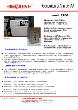
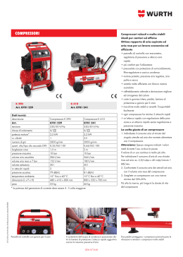
Italiano
English
Compressore ad alta pressione per aria respirabile e gas tecnici
High pressure compressors for pure breathing air and technical gases
MANUALE USO E MANUTENZIONE
USE AND MAINTENANCE MANUAL
MCH-6
ITALIANO
ENGLISH
AVVERTENZA: PRIMA DI UTILIZZARE IL COMPRESSORE
LEGGERE CON ATTENZIONE IL PRESENTE MANUALE.
IMPORTANT: BEFORE USING THE COMPRESSOR READ THIS
MANUAL CAREFULLY.
AVVERTENZA: PRIMA DI ESEGUIRE QUALSIASI OPERAZIONE
SUL MOTORE, CONSULTARE IL MANUALE USO E
MANUTENZIONE DEL MOTORE ALLEGATO.
IMPORTANT: BEFORE CARRYING OUT ANY WORK ON
THE ENGINE CONSULT THE ATTACHED ENGINE USE AND
MAINTENANCE MANUAL.
AVVERTENZA:
I compressori vengono consegnati privi delle fruste di
ricarica, dell’olio di lubrificazione del compressore, dell’olio di
lubrificazione del motore a scoppio e delle cartucce filtranti
che vengono forniti in dotazione all’interno dell’imballo.
WARNING:
The compressors are delivered without the refill hoses,
compressor lubricating oil, combustion engine lubricating
oil or filtration cartridge: these items are supplied inside the
packaging.
MCH-6
MCH-6
COMPRESSORI AD ALTA PRESSIONE
PER ARIA RESPIRABILE E GAS TECNICI
HIGH PRESSURE COMPRESSORS
FOR PURE BREATHING AIR AND TECHNICAL GASES
Gentile cliente,
nel ringraziarLa per aver scelto un compressore “AEROTECNICA COLTRI”,
abbiamo il piacere di consegnarLe il presente manuale, al fine di consentirLe
un uso ottimale del nostro prodotto per una miglior riuscita del Suo lavoro.
Dear Customer,
Thank you for choosing an AEROTECNICA COLTRI compressor. This manual
is provided together with the compressor to aid you in the use of the
machine and ensure that your work produces the best possible results.
La invitiamo a leggere con molta cura le raccomandazioni riportate nelle
pagine a seguire e di mettere il manuale a disposizione del personale che si
occuperà della gestione e della manutenzione del compressore.
Please read all the instructions and information provided on the following
pages. Ensure that the manual is at the disposal of the personnel who will
be using/managing the compressor and carrying out any maintenance on
it.
AEROTECNICA COLTRI è a sua completa disposizione per tutti gli eventuali
chiarimenti di cui Lei avesse bisogno sia nella fase di avviamento del
compressore che in ogni momento di utilizzo dello stesso.
In caso di eventuali vs. richieste contattateci al nostro fax:
+39 030 9910283
Nei momenti in cui saranno necessarie operazioni di manutenzione
ordinaria o straordinaria, AEROTECNICA COLTRI mette sin d’ora a Sua
disposizione il proprio Servizio tecnico internazionale per fornirLe tutta
l’assistenza ed i ricambi.
Per un più rapido rapporto di collaborazione vi elenchiamo inoltre come
contattarci:
Should you require any clarification, when using the compressor for the first
time or at any other time it is used, please remember that AEROTECNICA
COLTRI is at your complete disposal.
Should you need to contact us our fax number is:
+39 030 9910283
For routine or unscheduled maintenance note that AEROTECNICA COLTRI
international technical service is able to provide you with assistance and
spare parts as and when required.
To ensure that your requests are dealt quickly, the following information is
provided:
AEROTECNICA COLTRI®
Via Colli Storici, 177
25010 SAN MARTINO DELLA BATTAGLIA (BS) ITALY
Tel. +39 030 9910301 Fax. +39 030 9910283
www.coltrisub.it www.coltrisub.com
[email protected]
Il presente manuale è di proprietà della AEROTECNICA COLTRI SpA, ogni
riproduzione anche parziale è vietata.
MU-MCH6-0015
This manual is the property of AEROTECNICA COLTRI SpA. Reproduction,
whole or partial, is forbidden.
MCH-6
3 - 60
ENGLISH
ITALIANO
GUIDA RAPIDA
QUICK GUIDE
ATTENZIONE:
- Questa guida serve solo ed esclusivamente per un
approccio rapido all’uso del compressore.
- La presente guida non sostituisce in nessun caso il manuale
di uso e manutenzione.
- Si fa divieto di usare il compressore senza aver letto nella
sua integrità il manuale di uso e manutenzione.
WARNING:
- This guide is intended only as a rapid introduction to use of
the compressor.
- This guide is not meant to replace the use and maintenance
manual.
- This compressor must not be used before reading the
entire use and maintenance manual.
Operazioni preliminari:
- Posizionare il compressore nel luogo prescelto (Vedi Cap. “5”).
- Collegare se necessario la prolunga per la presa d’aria (Vedi Cap. “5.3.2”).
- Verificare il livello dell’olio; se il compressore è nuovo riempire la coppa
dell’olio con l’olio dato in dotazione al compressore (Vedi Cap. “7.6”).
- Verificare che all’interno del filtro ci sia la cartuccia filtrante (Vedi Cap.
“7.10”);
Per compressori con motore a scoppio:
- Verificare e nel caso rabboccare il livello del carburante (Vedi Cap. “7.7”).
Per compressori con motore elettrico:
- Collegare il motore elettrico alla presa di alimentazione della rete (Vedi
Cap. “5.3.3”).
- Per compressori equipaggiati con motore elettrico trifase, verificare che
la ventola di raffreddamento giri nel senso indicato dalla freccia che si
trova sul carter, se gira in senso contrario invertire due delle tre fasi tra
loro sull’alimentazione principale (Vedi Cap. “6.1.4”).
- Accendere il compressore con il rubinetto finale 1 collegato alla bombola
2 chiusa e scarichi condensa 3 chiusi e verificare che lo scarico libero della
valvola di sicurezza avvenga quando il valore sul manometro è uguale al
valore di taratura della valvola (Vedi Cap. “6.2.4”).
Ricarica bombole (Vedi Cap. “6.4”):
- montare l’attacco della frusta 1 sull’attacco della bombola 2 (chiuso);
- aprire il rubinetto scarico condensa 3 sul separatore;
- avviare il compressore;
- chiudere lo scarico;
- aprire il rubinetto della bombola 4;
- scaricare ogni 10-15 min di utilizzo, la condensa.
A ricarica avvenuta:
- spegnere il compressore;
- chiudere il rubinetto della bombola 4;
- aprire il rubinetto di scarico condensa 3 e lasciare defluire tutta l’aria;
- scollegare l’attacco 1 dalla bombola.
Manutenzione:
- Dopo le prime 5 ore di lavoro del compressore, sostituire nuovamente
l’olio (Vedi Cap. “7.6”).
- Verificare ogni 5 ore il livello dell’olio lubrificante (Vedi Cap. “7.6”).
- Sostituire ogni 50 ore l’olio lubrificante (Vedi Cap. “7.6”).
- Sostituire periodicamente il filtro di aspirazione (Vedi Cap. “7.8”).
- Scaricare la condensa (Vedi Cap.“7.9”).
- Sostituire periodicamente le cartucce filtranti (Vedi Cap. “7.10”).
- Verificare la tensione delle cinghie di trasmissione e se necessario
sostituirle (Vedi Cap.“7.11”).
- Sostituire periodicamente le fruste (Cap. “7.12”).
Preliminary tasks:
- Position the compressor in the selected area (see section “5”).
- If necessary connect the air intake extension (see section “5.3.2”).
- Check the oil level; if the compressor is new fill the oil sump with the oil
supplied with the compressor (see section “7.6”).
- Check that the cartridge is inside the filtration cartridge (see chap “7.10”);
For compressors with combustion engines:
- Check fuel level and top up if necessary (see section “7.7”).
For compressors with electric motors:
- Connect the electric motor to the mains power socket (see section
“5.3.3”).
- For compressors equipped with a three-phase electric motor, check
that the cooling fan rotates in the direction indicated by the arrow on
the cover; if it turns the other way invert two of the three phases on the
mains power (see section “6.1.4”).
- Switch on the compressor with the fill valve 1 connected to the closed
bottle 2 and the condensate outlets 3 closed and check that free drainage
of the safety valve occurs when the value on the gauge is the same as the
calibration value of the valve (see section “6.2.4”).
Bottle refill (see section “6.4”):
- fit the hose connector 1 on the bottle connector 2 (closed) (A);
- open the condensate discharge valve 3 on the separator (B);
- start the compressor (C);
- close the discharge (B).
- open the tank valve 4 (A);
- discharge the condensate every 10-15 minutes of use (B).
When refill is complete:
- switch off the compressor (C);
- close the bottle valve 4 (A);
- open the condensate discharge valve 3 and let all the air bleed out (B);
- disconnect the coupling 1 from the bottle (A).
Maintenance:
- After the first 5 working hours change the oil again (see section “7.6”).
- Check the lubricating oil level every 5 hours (see section “7.6”).
- Change the lubricating oil every 50 hours (see section “7.6”).
- Periodically change the air intake filter (see section “7.8”).
- Discharge the condensate (see section “7.9”).
- Periodically change the filtration cartridge (see section “7.10”).
- Check transmission belt tension and if necessary change them (see section
“7.11”).
- Periodically change the hoses (see section “7.12”).
3
2
C
3
A
1
A C
4
a) Start
b) Stop
4 - 60
b
a
a
b
b
a
MCH-6
MU-MCH6-0015
ENGLISH
ITALIANO
INDICE
CONTENTS
1 - DESCRIZIONE GENERALE
1.1 Informazioni preliminari
1.2 Formazione richiesta all’operatore
1.3 Avvertenze per l’uso
1.4 Premessa
1.5 Garanzia
1.6 Assistenza
1.7 Responsabilità
1.8 Uso previsto
1.9 Ambiente di utilizzo previsto
1.10 Rodaggio e collaudo del compressore
1.10.1 Valori coppia di serraggio
7
7
7
7
8
8
9
9
10
11
11
12
1 - GENERAL
1.1 Preliminary information
1.2 Required operator training
1.3 Important information for the user
1.4 Foreword
1.5 Warranty
1.6 Assistance
1.7 Responsibility
1.8 Purpose of the machine
1.9 Where the machine may be used
1.10 Running in and testing the compressor
1.10.1 Tightening torque values
7
7
7
7
8
8
9
9
10
11
11
12
2 - CARATTERIZZAZIONE DEL COMPRESSORE
2.1 Descrizione del compressore
2.2 Identificazione del compressore
2.3 Istruzioni generali
12
12
12
13
2 - BASIC INFORMATION ON THE COMPRESSOR
2.1 Description of the compressor
2.2 Identification the compressor
2.3 General instructions
12
12
12
13
3 - PRESCRIZIONI DI SICUREZZA
3.1 Norme di sicurezza generali
3.1.1 Conoscere a fondo il compressore
3.1.2 Portare indumenti protettivi
3.1.3 Usare un’attrezzatura di sicurezza
3.1.4 Avvertenze per le verifiche e la manutenzione
3.2 Precauzioni generali
3.2.1 Avvertenze di sicurezza
3.2.2 Sicurezza antinfortunistica
3.2.3 Sicurezza di esercizio
3.2.4 Livello sonoro
3.2.5 Zone a rischio residuo
3.3 Ubicazione delle targhette di sicurezza
3.3.1 Descrizione delle targhette di sicurezza
3.4 Regole generali di sicurezza
3.4.1 Cura e manutenzione
3.4.2 Estintore incendi e primo soccorso
3.5 Precauzioni per la manutenzione
3.5.1 Sostituzione periodica delle parti fondamentali per la sicurezza
3.5.2 Attrezzi
3.5.3 Personale
3.5.4 Mantenere pulito il compressore
3.5.5 Targhe di avvertenza
13
13
13
14
14
14
14
16
16
16
16
16
17
18
20
20
20
20
20
20
21
21
21
3 - SAFETY REGULATIONS
3.1 General safety rules
3.1.1 Know the machine
3.1.2 Protective clothing
3.1.3 Emergency equipment
3.1.4 Checks and maintenance
3.2 General precautions
3.2.1 Important safety information
3.2.2 Accident prevention
3.2.3 Working safety
3.2.4 Noise level
3.2.5 Residual risk zones
3.3 Safety info labels: location
3.3.1 Safety info labels: description
3.4 General safety regulations
3.4.1 Care and maintenance
3.4.2 Fire extinguishers and first aid
3.5 Maintenance precautions
3.5.1 Periodic replacement of essential safety parts
3.5.2 Tools
3.5.3 Personnel
3.5.4 Keeping the compressor clean
3.5.5 Warning signs
13
13
13
14
14
14
14
16
16
16
16
16
17
18
20
20
20
20
20
20
21
21
21
4 - DATI TECNICI
4.1 Caratteristiche tecniche
4.1.1 Monoblocco, collo d’oca, pistoni, cilindri
4.1.2 Valvole
4.1.3 Valvole di sicurezza
4.1.4 Lubrificazione
4.1.5 Tubi di raffreddamento
4.1.6 Telaio, carter di protezione
4.17 Manometri
4.2 Nomenclatura
4.3 Tabella caratteristiche tecniche
4.4 Circuito di pressione
4.5 Schema elettrico
21
21
21
21
21
21
22
22
22
23
24
29
29
4 - TECHNICAL DATA
4.1 Technical characteristics
4.1.1 Crankcase, crankshaft, cylinder, pistons
4.1.2 Valves
4.1.3 Safety valves
4.1.4 Lubrication
4.1.5 Cooling tubes
4.1.6 Frame, guards
4.1.7 Pressure gauges
4.2 Machine parts
4.3 Technical characteristics
4.4 Pressure circuit
4.5 Wiring diagram
21
21
21
21
21
21
22
22
22
23
24
29
29
5 - MOVIMENTAZIONE E INSTALLAZIONE
5.1 Imballaggio
5.2 Movimentazione
5.3 Installazione
5.3.1 Posizionamento
5.3.2 Collegamento prolunga per presa d’aria
5.3.3 Collegamento elettrico
30
30
30
31
31
32
32
5 - HANDLING AND INSTALLATION
5.1 Unpacking
5.2 Handling
5.3 Installation
5.3.1 Positioning
5.3.2 Air intake extension connection
5.3.3 Electrical connection
30
30
30
31
31
32
32
6 - USO DEL COMPRESSORE
6.1 Controlli preliminari della prima messa in servizio
6.1.1 Riempimento olio lubrificante
6.1.2 Inserimento cartuccia filtrante
6.1.3 Riempimento olio lubrificante motore
(solo per motori a scoppio)
6.1.4 Verifica collegamento fasi elettriche
(solo per motori elettrici trifase)
6.1.5 Collegamento fruste di ricarica
33
33
33
33
33
6 - USING THE COMPRESSOR
6.1 Preliminary checks before using for the first time
6.1.1 Filling with lubricating oil
6.1.2 Inserting filtration cartridge
6.1.3 Filling the engine with lubricating oil
(for internal combustion engine only)
6.1.4 Checking for proper electrical connection
(for three-phase electric motor only)
6.1.5 Refill hoses connection
33
33
33
33
33
MU-MCH6-0015
33
33
MCH-6
33
33
5 - 60
ENGLISH
ITALIANO
6.2 Controlli prima dell’inizio di ogni giornata lavorativa
6.2.1 Verifica livello olio lubrificante
6.2.2 Controllo dell’integrità delle fruste di ricarica
6.2.3 Verifica del livello carburante
6.2.4 Verifica valvole di sicurezza
6.2.5 Custodia documentazione tecnica
6.3 Avviamento e spegnimento
6.3.1 Avviamento e spegnimento con motore ascoppio
6.3.2 Avviamento e spegnimento con motore elettrico
6.3.3 Spegnimento automatico con pressostato
6.4 Ricarica bombole
6.5 Optional
6.5.1 Spegnimento automatico con pressostato
6.5.2 Scarico condensa automatico
6.5.3 Contaore
6.5.4 Riduttore di pressione 300/225 bar
34
34
34
34
35
35
36
36
37
37
38
40
40
40
40
40
6.2 Checks to be run at the start of each working day
6.2.1 Lubricating oil level check
6.2.2 Checking that the flex hoses are in good condition
6.2.3 Fuel level check
6.2.4 Checking the safety valves
6.2.5 Storing technical documentation
6.3 Starting and shutting down
6.3.1 Starting and shutting down with internal combustion engine
6.3.2 Starting and shutting down with electric motor
6.3.3 Automatic shutdown with pressure switch
6.4 Tank refill
6.5 Optional
6.5.1 Automatic shutdown with pressure switch
6.5.2 Automatic condensate discharge
6.5.3 Hour counter
6.5.4 Pressure reducer 300/225 bar
34
34
34
34
35
35
36
36
37
37
38
40
40
40
40
40
7 - MANUTENZIONE
7.1 Premessa
7.2 Norme generali
7.3 Interventi straordinari
7.4 Tabella manutenzioni programmate
7.5 Tabella guasti e anomalie
7.6 Controllo e sostituzione olio lubrificante
7.7 Controllo e rabbocco carburante
7.8 Sostituzione filtro di aspirazione
7.9 Scarico condensa
7.10 Filtro depuratore
7.10.1 Tabella calcolo intervalli di sostituzione cartuccia
filtrante
7.10.2 Sostituzione cartuccia filtrante
7.11 Cinghia di trasmissione
7.11.1 Verifica tensione e sostituzione della cinghia di
trasmissione
7.12 Sostituzione frusta
41
41
41
42
42
43
44
46
46
47
48
48
41
41
41
42
42
43
44
46
46
47
48
48
51
7 - MAINTENANCE
7.1 Foreword
7.2 General
7.3 Unscheduled work
7.4 Scheduled maintenance table
7.5 Troubleshooting
7.6 Checking and changing the lubricating oil
7.7 Checking fuel level and topping up
7.8 Changing the intake filter
7.9 Condensate discharge
7.10 Purifier filter
7.10.1 Filtration cartridge replacement frequency calculation
table
7.10.2 Changing the filtration cartridge
7.11 Transmission belt
7.11.1 Checking transmission belt tension / changing
belts
7.12 Changing the flex hose
8 - IMMAGAZZINAMENTO
8.1 Fermo macchina per brevi periodi
8.2 Fermo macchina per lunghi periodi
52
52
52
8 - STORAGE
8.1 Stopping the machine for a brief period
8.2 Stopping the machine for a long period
52
52
52
9 - SMANTELLAMENTO, MESSA FUORI SERVIZIO
9.1 Smaltimento dei rifiuti
9.2 Smantellamento del compressore
53
53
53
9 - DISMANTLING AND PUTTING OUT OF SERVICE
9.1 Waste disposal
9.2 Dismantling the compressor
53
53
53
10 - REGISTRO DELLE MANUTENZIONI
10.1 Servizio di assistenza
10.2 Interventi di manutenzione programmata
10.3 Utilizzo del compressore in condizioni gravose
10.4 Il Customer Care Centre
10.5 Tagliandi registro manutenzioni programmate
54
54
54
54
54
55
10 - MAINTENANCE REGISTER
10.1 Assistance service
10.2 Scheduled maintenance
10.3 Using the compressor under heavy-duty conditions
10.4 The Customer Care Centre
10.5 Scheduled maintenance registry coupons
54
54
54
54
54
55
6 - 60
MCH-6
49
50
50
MU-MCH6-0015
49
50
50
51
ENGLISH
ITALIANO
1 - DESCRIZIONE GENERALE
1.1
INFORMAZIONI PRELIMINARI
1 – GENERAL
1.1
PRELIMINARY INFORMATION
Non distruggere, non modificare, integrare solo con fascicoli aggiuntivi
pubblicati dal produttore.
Do not destroy or modify the manual and update it with inserts published
by producer only.
Tipo di macchina: Compressore ad alta pressione
per aria respirabile e/o gas tecnici
Modello:MCH-6
Revisione n°: 00
Edizione:04/2015
Dati costruttore: AEROTECNICA COLTRI SpA
Via Colli Storici, 177
25010 SAN MARTINO DELLA BATTAGLIA (BRESCIA)
ITALY
Telefono: +39 030 9910301 - +39 030 9910297
Fax: +39 030 9910283
http: www.coltrisub.it - www.coltrisub.com
e-mail:[email protected]
Machine type: High pressure compressor for breathing air
and/or technical gases
Model:MCH-6
Revision n°: 00
Manual version: 04/2015
Manufacturer’s data: AEROTECNICA COLTRI SpA
Via Colli Storici, 177
25010 SAN MARTINO DELLA BATTAGLIA (BRESCIA)
ITALY
Telephone: +39 030 9910301 - +39 030 9910297
Fax: +39 030 9910283
http: www.coltrisub.it - www.coltrisub.com
e-mail:[email protected]
1.2
FORMAZIONE RICHIESTA ALL’OPERATORE
Attenta lettura del presente manuale:
- ogni operatore e personale addetto alla manutenzione del
compressore dovrà leggere interamente con la massima attenzione il
presente manuale e rispettare quanto è riportato.
- l’operatore deve possedere i requisiti attitudinali alla conduzione del
compressore ed abbia preso attenta visione del manuale.
1.3
AVVERTENZE PER L’USO
1.2
REQUIRED OPERATOR TRAINING
This manual must be read carefully:
- all compressor operators / maintenance personnel must read this entire
manual with due care and attention and observe the instructions/
information contained herein.
- the operator must possess the required training for operation of the
compressor and that he/she has read the manual.
1.3
IMPORTANT INFORMATION FOR THE USER
Le norme d’esercizio contenute nel presente manuale valgono
esclusivamente per i compressori AEROTECNICA COLTRI Mod.:
MCH-6
The information/instructions for compressor use contained in this manual
only concern the AEROTECNICA COLTRI Mod.:
MCH-6
Il manuale istruzioni deve essere letto ed utilizzato nel seguente modo:
-leggere attentamente il manuale istruzioni e considerarlo parte
integrante del compressore;
- il manuale istruzioni deve essere facilmente reperibile dal personale
addetto alla guida ed alla manutenzione;
- custodire il manuale per tutta la durata del compressore;
- assicurarsi che qualsiasi aggiornamento pervenuto venga incorporato
nel testo;
- consegnare il manuale a qualsiasi altro utente o successivo proprietario
del compressore;
- impiegare il manuale in modo tale da non danneggiare tutto o in parte il
contenuto;
- non asportare, strappare o riscrivere per alcun motivo parti del manuale;
- conservare il manuale in zone protette da umidità e calore;
- nel caso il manuale venga smarrito o parzialmente rovinato e quindi non
sia più possibile leggere completamente il suo contenuto è opportuno
richiedere un nuovo manuale alla casa costruttrice.
The instruction manual must be read and used as follows:
- read this manual carefully, treat it as an essential part of the compressor;
- the instruction manual must be kept where it can readily be consulted by
compressor operators and maintenance staff;
- keep the manual for the working life of the compressor;
- make sure updates are incorporated in the manual;
- make sure the manual is given to other users or subsequent owners in
the event of resale;
- keep the manual in good condition and ensure its contents remain
undamaged;
- do not remove, tear or re-write any part of the manual for any reason;
- keep the manual protected from damp and heat;
- if the manual is lost or partially damaged and its contents cannot be read
it is advisable to request a copy from the manufacturer.
Important: you must understand the following symbols and their meaning.
They highlight essential information:
Prestare la massima attenzione ai seguenti simboli ed al loro significato. La
loro funzione è dare rilievo ad informazioni particolari quali:
AVVERTENZA: In riferimento ad integrazioni o suggerimenti
per l’uso corretto della macchina.
IMPORTANT: Refers to additional information or suggestions
for proper use of the compressor.
PERICOLO: In riferimento a situazioni di pericolo che si
possono verificare con l’uso della macchina per garantire la
sicurezza alle persone.
DANGER: Refers to dangerous situations that may occur
during use of the compressor: aims to ensure worker safety.
ATTENZIONE: In riferimento a situazioni di pericolo che si
possono verificare con l’uso della macchina per evitare danni
a cose ed alla macchina stessa.
WARNING: Refers to dangerous situations that may occur
during use of the compressor: aims to prevent damage to
objects and the compressor itself.
MU-MCH6-0015
MCH-6
7 - 60
ENGLISH
ITALIANO
1.4
PREMESSA
1.4
Le norme di servizio descritte nel presente manuale, costituiscono parte
integrante della fornitura del compressore.
Tali norme, inoltre, sono destinate all’operatore già istruito espressamente
per condurre questo tipo di compressore e contengono tutte le
informazioni necessarie ed indispensabili per la sicurezza di esercizio e
l’impiego ottimale, non scorretto, del compressore.
Preparazioni affrettate e lacunose costringono all’improvvisazione e ciò è
causa di molti incidenti.
Prima di iniziare il lavoro, leggere attentamente e rispettare scrupolosamente
i seguenti suggerimenti:
- prendere confidenza, prima di iniziare ad usare il compressore, di
qualsiasi operazione e posizione ammissibile di esercizio;
- l’operatore deve sempre avere in qualsiasi momento a disposizione il
manuale istruzioni;
- programmare ogni intervento con cura;
- conoscere dettagliatamente dove e come è previsto l’impiego del
compressore;
- prima di iniziare i lavori assicurarsi che i dispositivi di sicurezza funzionino
correttamente e non si abbiano dubbi sul loro funzionamento; in caso
contrario non utilizzare in nessun caso il compressore;
- osservare accuratamente le avvertenze relative a pericoli speciali
riportate in questo manuale;
- una manutenzione preventiva costante ed accurata garantisce sempre
l’elevata sicurezza di esercizio del compressore. Non rimandare mai
riparazioni necessarie e farle eseguire solo ed esclusivamente da
personale specializzato, ed impiegare soltanto ricambi originali.
1.5
GARANZIA
1.5
WARRANTY
AVVERTENZA: I materiali forniti da AEROTECNICA COLTRI SpA
godono di una garanzia di 1 anno a decorrere dalla messa in
servizio, comprovata dal documento di consegna.
AEROTECNICA COLTRI SpA si riserva di riparare, o sostituire,
i pezzi da essa riconosciuti difettosi durante il periodo di
garanzia.
IMPORTANT: The materials supplied by AEROTECNICA COLTRI
SpA are covered by a 1 year warranty, the validity of which
begins when the compressor is put into service as proven by
the delivery document.
Con la sostituzione del pezzo ritenuto difettoso,
AEROTECNICA COLTRI SpA si ritiene libera da qualsiasi
altra spesa sostenuta dal Concessionario e dal Cliente del
Concessionario come danno presunto, presente o futuro, tipo
mancato guadagno, pena convenzionale.
In replacing the faulty part AEROTECNICA COLTRI SpA shall
not be liable for any other expenses sustained by the dealer
or his customer such as presumed damage (present or future),
lost earnings or fines.
Le manutenzioni ordinarie e straordinarie devono
avvenire in accordo alle istruzioni contenute nel presente
manuale. Per tutti i casi non compresi e per ogni genere
di assistenza si raccomanda di contattare direttamente
AEROTECNICA COLTRI SpA in forma scritta, anche nel caso
di accordi presi telefonicamente. AEROTECNICA COLTRI SpA
non si assume nessuna responsabilità per eventuali ritardi o
mancati interventi.
AEROTECNICA COLTRI SpA non si ritiene responsabile di
eventuali danni o malfunzionamenti dovuti ad interventi
tecnici eseguiti sul compressore da personale non autorizzato.
AEROTECNICA COLTRI SpA garantisce i compressori da qualsiasi vizio o
difetto di progettazione, di fabbricazione o del materiale utilizzato, che
eventualmente dovesse manifestarsi entro 1 anno dalla consegna del
compressore; il cliente deve annunciare alla AEROTECNICA COLTRI SpA i
vizi e/o difetti eventualmente riscontrati entro 8 giorni dalla scoperta, per
iscritto, pena decadenza della garanzia.
La garanzia vale solo per i vizi e difetti che si manifestino nelle condizioni
di corretto impiego del compressore, seguendo le istruzioni del presente
manuale ed effettuando la previste manutenzioni periodiche.
Sono espressamente esclusi dalla garanzia guasti derivanti da un uso
improprio del compressore, da agenti atmosferici, da danneggiamenti
imputabili al trasporto; tutti i materiali di consumo e di manutenzione
periodica non rientrano nella garanzia e sono interamente a carico del
8 - 60
FOREWORD
The regulations/instructions for use contained in this manual constitute an
essential component of the supplied compressor.
These regulations/instructions are intended for an operator who has
already been trained to use this type of compressor. They contain all the
information necessary and essential to safety and efficient, proper use of
the compressor.
Hurried or careless preparation leads to improvisation, which is the cause
of accidents.
Before beginning work, read the following suggestions carefully:
- before using the compressor, gain familiarity with the tasks to be
completed and the admissible working position;
- the operator must always have the instruction manual to hand;
- program all work with due care and attention;
- you must have a detailed understanding of where and how the
compressor is to be used;
- before starting work make sure that safety devices are working properly
and that their use is understood; in the event of any doubts do not use
the compressor;
- observe the warnings given in this manual with due care and attention;
- constant and careful preventive maintenance will always ensure a high
level of safety when using the compressor. Never postpone repairs and
have them carried out by specialised personnel only; use only original
spare parts.
MCH-6
AEROTECNICA COLTRI SpA shall repair or replace those parts
it acknowledges to be faulty during the warranty period.
Routine and unscheduled maintenance must be carried
out in compliance with the instructions contained in this
manual. Should the required work not be covered by the
manual or assistance be required you are advised to contact
AEROTECNICA COLTRI SpA in writing, even where agreements
have already been made on the phone. AEROTECNICA COLTRI
SpA cannot be held liable for any delays or failure to execute
work.
AEROTECNICA COLTRI SpA cannot be held liable for any
damage or malfunctions caused by work carried out on the
compressor by unauthorised personnel.
AEROTECNICA COLTRI SpA guarantees that its compressors are free from
defects design, workmanship and th e used materials for a period of 1
year starting from the date of delivery of the compressor; should the
customer note any flaws and/or defects he must report them, in writing,
to AEROTECNICA COLTRI SpA within 8 days of their discovery otherwise the
warranty shall be rendered null and void.
The warranty only covers flaws and faults that occur where the compressor
is used properly in compliance with the instructions contained in this
manual and where periodic maintenance is carried out.
The warranty does not cover faults caused by improper use of the
compressor, exposure to atmospheric agents (rain etc.) or damage during
transport; all materials subject to wear and those subject to periodic
maintenance are not covered by the warranty and are to be paid for by the
MU-MCH6-0015
ENGLISH
ITALIANO
cliente; in ogni caso la garanzia decade automaticamente ove il compressore
abbia subito manomissioni od interventi da parte di tecnici non autorizzati
dalla AEROTECNICA COLTRI SpA.
Il compressore che sia stato riconosciuto difettoso per vizi di progettazione,
di fabbricazione o del materiale, verrà riparato o sostituito gratuitamente
da AEROTECNICA COLTRI SpA presso il proprio stabilimento in San Martino
della Battaglia (BRESCIA); sono a carico esclusivo del cliente le spese di
trasporto, spedizione per i pezzi di ricambio ed eventuali materiali di
consumo.
Qualora sia necessario un intervento in garanzia presso il cliente, sono a
carico di quest’ultimo le spese vive di viaggio e trasferta per il personale
inviato da AEROTECNICA COLTRI SpA.
La presa in consegna delle macchine e/o di eventuali componenti difettosi
o le eventuali trasferte, per la verifica di difetti e/o vizi denunciati dal cliente
non comporteranno, in ogni caso, alcun riconoscimento implicito in ordine
all’operatività della garanzia.
Riparazioni e/o sostituzioni effettuate da AEROTECNICA COLTRI SpA ,
durante il periodo di garanzia, non prolungano la durata della stessa.
Il riconoscimento della garanzia non comporta di per se alcuna
responsabilità risarcitoria a carico di AEROTECNICA COLTRI SpA.
Per quanto riguarda eventuali danni a persone e cose, nonché ogni
altro danno diretto o indiretto (mancata produzione o lucro cessante
ecc.), eventualmente imputabile a vizi e difetti del compressore,
AEROTECNICA COLTRI SpA non assume alcuna responsabilità, al di fuori dei
casi in cui sia ravvisabile una colpa grave a suo carico.
1.6
ASSISTENZA
I tecnici di AEROTECNICA COLTRI SpA sono disponibili per qualsiasi
intervento di manutenzione ordinaria e straordinaria.
La richiesta di intervento deve essere inoltrata ad AEROTECNICA COLTRI SpA
inviando un fax o una e-mail ai seguenti numeri:
Fax. +39 030 9910283
[email protected]
1.7
RESPONSABILITÀ
AEROTECNICA COLTRI SpA si ritiene esonerata da ogni responsabilità
ed obbligazione per qualsiasi incidente a persone o a cose, che possano
verificarsi a causa di:
- mancata osservanza delle istruzioni riportate nel presente manuale
per quanto riguarda la conduzione, l’impiego e la manutenzione del
compressore;
- azioni violente o manovre errate nell’impiego e nella manutenzione del
compressore;
- modifiche apportate al compressore senza previa autorizzazione scritta
da AEROTECNICA COLTRI SpA;
-avvenimenti comunque estranei al normale e corretto uso del
compressore.
In ogni caso, qualora l’utente imputasse l’incidente ad un difetto del
compressore, dovrà dimostrare che il danno avvenuto è stato una principale
e diretta conseguenza di tale “difetto”.
ATTENZIONE: Per le operazioni di manutenzione o riparazioni
fare sempre uso esclusivo di pezzi di ricambio originali.
AEROTECNICA COLTRI SpA declina ogni responsabilità per
danni che si dovessero verificare per inadempienza di quanto
sopra.
Il compressore è garantito secondo gli accordi contrattuali
stipulati alla vendita.
La garanzia tuttavia decade qualora non siano state osservate
le norme ed istruzioni d’uso previste dal presente manuale.
MU-MCH6-0015
customer in full; in any event the warranty is rendered null and void if the
compressor is tampered with or if work is carried out on it by
personnel who have not been authorised by AEROTECNICA COLTRI SpA.
A compressor that has been acknowledged as faulty on account of flaws in
design, workmanship or used materials shall be repaired or replaced free
of charge by AEROTECNICA COLTRI SpA at its plant in San Martino della
Battaglia (BRESCIA); costs regarding transport, delivery of spare parts and
any materials subject to wear shall be met by the customer.
Should warranty-covered work need to be carried out on the customer’s
premises, travel and accommodation costs for personnel sent by
AEROTECNICA COLTRI SpA. shall be met by the customer.
The act of taking delivery of machines and/or faulty components or
the sending of technicians to assess the presumed defects and/or flaws
reported by the customer does not in itself imply acknowledgement that
the defect is covered by warranty.
Repairs and/or replacements made by AEROTECNICA COLTRI SpA during
the warranty period do not in any way prolong the latter itself.
Acknowledgement that a defect is covered by warranty does not in
itself mean that AEROTECNICA COLTRI SpA is in any way liable to award
compensation.
AEROTECNICA COLTRI SpA cannot be held liable for any other direct or
indirect damages imputable to compressor defects and flaws (loss of
production or earnings etc.) except in cases where serious negligence is
demonstrated.
1.6
ASSISTANCE
AEROTECNICA COLTRI SpA technicians are at your disposal for all routine/
unscheduled maintenance work.
Please forward your request for assistance to AEROTECNICA COLTRI SpA by
sending a fax or e-mail to:
Fax. +39 030 9910283
[email protected]
1.7
RESPONSIBILITY
AEROTECNICA COLTRI SpA considers itself exonerated from any
responsibility or obligation regarding injury or damage caused by:
- failure to observe the instructions contained in this manual that concern
the running, use and maintenance of the compressor;
- violent actions or incorrect manoeuvres during use or maintenance of
the compressor;
-modifications made to the compressor without prior written
authorisation from AEROTECNICA COLTRI SpA;
- incidents beyond the scope of routine, proper use of the compressor.
In any case, should the user impute the incident to a defect of the
compressor, he/she must demonstrate that the damage has been a major
and direct consequence of this “defect”.
WARNING: Maintenance and repairs must only be carried out
using original spare parts.
AEROTECNICA COLTRI SpA cannot be held liable for any
damages caused by failure to observe this rule.
The compressor is guaranteed as per the contractual
agreements made at the time of sale.
Failure to observe the regulations and instructions for use
contained in this manual shall render the warranty null and
void.
MCH-6
9 - 60
ENGLISH
ITALIANO
1.8
USO PREVISTO
1.8
PURPOSE OF THE MACHINE
I compressori mod. MCH-6, sono previsti per ottenere aria respirabile di
ottima qualità prelevandola dall’ambiente circostante, priva di fumi nocivi,
tramite un apposito filtro di aspirazione e introdotta nelle bombole atte a
contenere aria ad alta pressione, dopo il ciclo di pompaggio e filtraggio.
Il compressore è previsto inoltre per ottenere aria non respirabile, ad uso
industriale, o altri gas quali:
-Azoto
-Elio
- Nitrox 40% max O2
Ogni altro utilizzo è da ritenersi non appropriato ed il costruttore declina
ogni responsabilità per eventuali danni a persone, cose o alla macchina
stessa che ne possono derivare.
The compressors mod. MCH-6 have been designed and built for the purpose
of obtaining excellent quality breathing air by drawing it from the surrounding
environment. The air, which must be free from any harmful fumes, is passed
through an intake filter and, after the pumping and filtration cycle, is stored
in bottles constructed to contain air at high pressure.
The compressor can also be used to obtain other non-breathable gases for
industrial use such as:
- Nitrogen
- Helium
- Nitrox 40% max O2
Any other use is inappropriate: the manufacturer cannot be held liable for
any personal injury or damage to objects / the machine itself caused by
improper use.
PERICOLO:
-Utilizzare solo le bombole collaudate con relativo
certificato e non superare la pressione di esercizio riportata
sulle stesse.
- Aspirare aria non viziata ne inquinata.
Utilizzare il compressore in ambienti dove non esistano
polveri e pericoli di esplosione, corrosione, incendio.
- Si fa divieto di utilizzare il compressore con motorizzazione
a scoppio in ambienti chiusi.
Assicurarsi che la presa d’aria sia lontana dai fumi di scarico.
- Un utilizzo non conforme a quanto previsto potrebbe
causare gravi conseguenze all’utilizzatore.
- Non sconnettere la frusta dai raccordi o dalla staffa quando
è sotto pressione.
- Spurgare regolarmente la condensa come illustrato nel
paragrafo “7.9 Scarico condensa”.
- Sostituire regolarmente i filtri di depurazione dell’aria
come descritto nel paragrafo “7.10.2 Sostituzione cartuccia
filtrante”.
- La spina di alimentazione elettrica va disinserita:
- in caso di inconveniente durante l’uso
- prima di ogni pulizia o manutenzione
- Non estrarre mai la spina tirando il cavo. Fare in modo
che il cavo non si pieghi ad angolo o passi contro spigoli
taglienti. Si sconsiglia l’uso di prolunghe.
- Il compressore non va mai messo in funzione quando:
- il cavo elettrico è danneggiato;
- presenta danni evidenti;
- i carter di protezione non sono montati.
-Tutte le operazioni di manutenzione ordinaria e
straordinaria vengono effettuate con il compressore fermo,
scollegando l’alimentazione elettrica e con il circuito di
pompaggio depressurizzato.
-Attendere circa 30 minuti dallo spegnimento del
compressore prima di intervenire per eventuali
manutenzioni onde evitare scottature.
- Il tubo flessibile ad alta pressione di collegamento alla
bombola chiamato anche frusta di ricarica deve essere in
buone condizioni soprattutto nella zona dei raccordi.
La guaina di plastica che ricopre il tubo non deve
presentare escoriazioni altrimenti l’umidità, infiltrandosi,
potrebbe corrodere la treccia d’acciaio riducendone la
resistenza.
La frusta va sostituita periodicamente (annualmente) o
quando presenta segni di usura. La non osservanza della presente norma implica gravi
pericoli agli operatori.
Osservare che il raggio minimo di curvatura della frusta
non sia inferiore a 250mm.
DANGER:
- Use only tested, certified bottles: do not exceed the
working pressure indicated on them.
- Aspirate unpolluted air.
Use the compressor in areas free from dust, risk of
explosion, corrosion and fire.
- It is forbidden to use the compressor with an internal
combustion engine indoors.
Make sure that air intakes are a long way from fume
exhausts.
- Improper use could have serious consequences for the
user .
- Do not disconnect the hose from the fittings or the clamp
when it is under pressure.
- Drain the condensate regularly as illustrated in section “7.9
Condensate discharge”.
- Change the air purification filters regularly as described in
section “7.10.2 Changing the filtration cartridge”.
- The power lead plug must be disconnected:
- if there is a problem during use
- before carrying out any cleaning or maintenance tasks.
- Never pull the plug out by tugging the lead. Make sure
the lead is not bent at a sharp angle and that it does not
rub against any sharp edges. Use of extensions is not
recommended.
- Never run the compressor when:
- the power lead is damaged;
- there is evident damage;
- the covers/guards are removed.
- All routine and unscheduled maintenance tasks must be
carried out with the compressor at standstill, the electrical
power supply disconnected and the pumping circuit
depressurised.
- After switching off the compressor wait about 30 minutes
before carrying out any maintenance tasks so as to prevent
burns.
- The high pressure flex hose that connects to the bottle
(also called the refill hose) must be in good condition,
especially in the areas near the fittings.
The plastic sheath that covers the pipe must not show any
signs of abrasion otherwise damp could get in, corrode the
steel braid and weaken it.
The hose must be changed periodically (yearly) or when it
shows signs of wear.
Failure to observe this rule could seriously endanger the
users’ safety.
Make sure the minimum bending radius of the hose is no
less than 250 mm.
Allo scopo di assicurare la massima affidabilità di esercizio, AEROTECNICA COLTRI
ha effettuato un’accurata scelta dei materiali e dei componenti da impiegare
nella costruzione dell’apparecchiatura, sottoponendola a regolare collaudo
prima della consegna. Il buon rendimento nel tempo del compressore dipende
anche da un corretto uso e da un’adeguata manutenzione preventiva secondo
le istruzioni riportate in questo manuale.
To ensure maximum working efficiency, AEROTECNICA COLTRI has
constructed the compressor with carefully selected components and
materials. The compressor is tested prior to delivery. Continued compressor
efficiency over time will also depend on proper use and maintenance as per
the instructions contained in this manual.
10 - 60
MCH-6
MU-MCH6-0015
ENGLISH
ITALIANO
Tutti gli elementi costruttivi, gli organi di collegamento e comando sono
stati progettati e realizzati con un grado di sicurezza tale da poter resistere a
sollecitazioni anomale o comunque superiori a quelle indicate nel presente
manuale. I materiali sono della migliore qualità e la loro introduzione in
azienda, lo stoccaggio e l’impiego in officina è costantemente controllato al
fine di garantire l’assenza di danni, deterioramenti, malfunzionamenti.
All the components, connections and controls used in its construction have
been designed and built to a high degree of safety so as to resist abnormal
strain or in any case a strain greater than that indicated in the manual.
Materials are of the finest quality; their introduction and storage in the
company and their utilisation in the workshop are controlled constantly so
as to prevent any damage, deterioration or malfunction.
ATTENZIONE:
- Prima di iniziare qualsiasi lavoro sul compressore ogni
operatore deve conoscere perfettamente il funzionamento
del compressore e dei suoi comandi ed aver letto e capito
tutte le informazioni tecniche contenute nel presente
manuale.
- Si fa divieto di impiegare il compressore in condizioni
o per uso diverso da quanto indicato nel presente
manuale e AEROTECNICA COLTRI non può essere ritenuta
responsabile per guasti, inconvenienti o infortuni dovuti
alla non ottemperanza a questo divieto.
-Controllare la tenuta dei raccordi bagnandoli con
dell’acqua e sapone ed eliminare le eventuali perdite.
- Non riparare le tubazioni ad alta pressione con delle
saldature.
- Non svuotare le bombole completamente, anche durante
lo stoccaggio invernale, onde evitare l’ingresso di aria
umida.
- Si fa divieto di manomettere, alterare o modificare, anche
parzialmente, gli impianti o le apparecchiature oggetto del
manuale di istruzione, ed in particolare i ripari previsti e i
simboli per la sicurezza delle persone.
- Si fa altresì divieto di operare in modo diverso da quanto
indicato o di trascurare operazioni necessarie alla sicurezza.
- Particolarmente importanti sono le indicazioni per la
sicurezza, oltre a informazioni di carattere generale
riportate su questo manuale.
DANGER:
- Before carrying out any work on the compressor each
operator must have a perfect understanding of how the
compressor works, know how to use the controls and have
read the technical information contained in this manual.
- It is forbidden to use the compressor under conditions /
for purposes other than those indicated in this manual
and AEROTECNICA COLTRI cannot be held liable for
breakdowns, problems or accidents caused by failure to
observe this rule.
- Check that the fittings provide a proper seal by wetting
them with soapy water: eliminate any leaks.
- Do not attempt to repair high pressure hoses by welding
them.
- Do not empty the bottles completely, not even during
winter storage, so as to prevent damp air getting in.
- It is forbidden to tamper with, alter or modify, even
partially, the systems and equipment described in this
instruction manual, especially as safety guards and safety
symbols are concerned.
- It is also forbidden to carry out work in any way other than
that described or to neglect the illustrated safety tasks.
- The safety information and the general information given
in this manual are highly important.
1.9
AMBIENTE DI UTILIZZO PREVISTO
1.9
WHERE THE MACHINE MAY
L’utilizzo del compressore deve avvenire in ambienti con le caratteristiche
descritte nella tabella seguente.
The compressor must only be used in environments having the
characteristics described in the following table.
TABELLA DATI SULL’AMBIENTE D’UTILIZZO PREVISTO
Min.-15°C (+5°F)
Temperatura ambiente
°C - (°F)
Max.+45°C (+113°F)
Umidità dell’aria
%
max.80%
pioggia
Agenti atmosferici tollerati
grandine
Nessuno
neve
Inclinazione max di utilizzo
%
6%
AREA OF MACHINE USE: ESSENTIAL DATA TABLE
Min.-15°C (+5°F) Temperature ambient
°C - (°F)
Max.+45°C (+113°F)
Air humidity
%
max.80%
rain
Tolerated weather conditions
hail
None
snow
Max tilt angle (bank)
%
6%
Verificare che nel luogo prescelto per il posizionamento ci siano le condizioni di
ventilazione adeguate: buon ricambio d’aria (presenza di più finestre), assenza
di polveri, non siano presenti rischi d’esplosione, di corrosione o d’incendio.
L’utilizzo in ambiente con temperature superiori a 45°C rende necessaria la
climatizzazione dell’ambiente d’impiego.
Accertarsi che al compressore giunga una sufficiente illuminazione, tale da
poter individuare facilmente ogni dettaglio (specie le scritte sulle targhette);
integrare la zona con luce artificiale se quella naturale non soddisfa i requisiti
citati.
Check that the area in which the compressor is to be positioned is
adequately ventilated: good air exchange with no dust and no risk of
explosion, corrosion or fire.
If ambient temperatures exceed 45°C air conditioning will be required.
Make sure that lighting in the area is sufficient to identify every detail
(such as the writing on the info plates/stickers); use artificial lighting where
daylight on its own is insufficient.
1.10 RODAGGIO E COLLAUDO DEL COMPRESSORE
Ogni compressore viene scrupolosamente rodato e collaudato prima della
consegna.
Un compressore nuovo deve comunque venire utilizzato con cautela per le
prime 5 ore, per eseguire un buon rodaggio dei vari componenti.
Se il compressore viene sottoposto ad un carico di lavoro eccessivo durante
la fase iniziale di funzionamento, il suo potenziale rendimento verrà
prematuramente compromesso e la sua funzionalità ridotta in un breve
lasso di tempo. Nel periodo di rodaggio, fare molta attenzione ai seguenti
punti:
Dopo le prime 5 ore, oltre alla manutenzione prevista, eseguire le seguenti
operazioni:
- sostituzione olio compressore;
- controllo e registrazione bulloneria.
MU-MCH6-0015
1.10 RUNNING IN AND TESTING THE COMPRESSOR
Each compressor is carefully run and tested prior to delivery.
A new compressor must nevertheless be used with caution during the first
5 working hours so as to complete proper running in of its components.
If the compressor is subject to an excessive workload during initial use, its
potential efficiency will be prematurely compromised and functionality
soon reduced. During the running in period proceed as follows:
After the first 5 hours carry out-in addition to the scheduled maintenance
- the following tasks:
- change the compressor oil;
- check and adjust nuts and bolts.
MCH-6
11 - 60
ITALIANO
ENGLISH
10.10.1 Valori coppia di serraggio
1.10.1
La tabella riporta i valori della coppia di serraggio per bulloni o viti a testa
esagonale o a testa cilindrica esagono incassato, salvo casi specifici indicati
nel manuale. Per collegamenti di tubi con dadi girevoli stringere il raccordo
a mano e poi ulteriormente di 1/2 giro.
Valori di coppia - Tightening torque values
Filettatura - Thread
Sequenza di serraggio per 6 e 4 bulloni - 6 and 4 bolt torque sequence
Coppia max. - Max. torque
M6 - 1/4”
10Nm (7ft-lbs)
M8 - 5/16”
25Nm (18ft-lbs)
M10 - 3/8”
45Nm (32ft-lbs)
M12 - 1/2”
75Nm (53ft-lbs)
M14 - 9/16”
120Nm (85ft-lbs)
M16 - 5/8”
200Nm (141ft-lbs)
2 - CARATTERIZZAZIONE DEL COMPRESSORE
2.1
2 - BASIC INFORMATION ON THE COMPRESSOR
DESCRIZIONE DEL COMPRESSORE
2.1
DESCRIPTION OF THE COMPRESSOR
PERICOLO: L’uso del compressore abbinato a miscelatori
Nitrox è consentito sino al 40% max. di ossigeno e con
sistemi certificati e dotati di sistema d’allarme e prevenzione
insufflaggio di percentuali di ossigeno superiori al consentito
e/o non miscelate correttamente.
DANGER: The compressor may be used together with Nitrox
mixers up to a maximum of 40% oxygen and only with
certified systems that feature an alarm system and that
prevent the introduction of oxygen percentages above the
permitted maximum and/or incorrect mixes.
AVVERTENZA: I compressori AEROTECNICA COLTRI forniscono
aria respirabile ad alta pressione conforme ai requisiti per la
qualità dell’aria specificati dalla normativa EN12021.
IMPORTANT: AEROTECNICA COLTRI compressors provide
breathable air at high pressure in compliance with EN12021
air quality requisites.
Compressore ad alta pressione per aria respirabile e gas tecnici.
Gas di processo compatibili:
-Azoto
-Elio
- Nitrox 40% max O2
2.2
Tightening torque values
The table shows tightening torques for hexagonal-head or cylindrical-head
recessed hexagonal bolts and screws, except for specific cases illustrated in
the manual. Pipe connections (swivel nuts) should be finger tight plus an
additional 1/2 turn.
High pressure compressor for breathing air and technical gases.
Compatible process gases:
-Nitrogen
-Helium
- Nitrox 40% max O2
IDENTIFICAZIONE DEL COMPRESSORE
2.2
Ogni singolo compressore è caratterizzato da una targhetta di
identificazione che si trova sul telaio del compressore.
IDENTIFICATION THE COMPRESSOR
Each compressor has an identification label attached to its frame.
AEROTECNICA COLTRI S.p.A.
Via Dei Colli Storici 177
25010 DESENZANO DEL GARDA (BRESCIA)
WWW.COLTRISUB.IT - MADE IN ITALY
MODEL
TYPE
S/N
YEAR
MOTOR
POWER
12 - 60
MCH-6
SC000000
000
3,6kW
MCH-6
2014
HONDA
NR. MON.
Lwa
000
75 db
MU-MCH6-0015
ENGLISH
ITALIANO
2.3
ISTRUZIONI GENERALI
2.3
ATTENZIONE:
- Il presente manuale deve essere letto molto attentamente
prima di trasportare, installare, usare o eseguire qualsiasi
manutenzione sul compressore.
- Deve essere conservato con cura in luogo noto all’utente
del compressore, ai responsabili, agli incaricati del
trasporto, installazione, uso, manutenzione, riparazione,
smantellamento finale.
-Il presente manuale indica l’utilizzo previsto del
compressore e fornisce istruzioni per il trasporto,
l’installazione, il montaggio, la regolazione e l’uso del
compressore. Fornisce informazioni per gli interventi di
manutenzione, l’ordinazione dei ricambi, la presenza di
rischi residui, l’istruzione del personale.
-E’ opportuno ricordare che il manuale di uso e
manutenzione non può mai sostituire una adeguata
esperienza dell’utilizzatore; per alcune operazioni di
manutenzione particolarmente impegnative il presente
manuale costituisce un promemoria delle principali
operazioni da compiere per operatori con preparazione
specifica acquisita, ad esempio, frequentando corsi di
istruzione presso il costruttore.
- Il presente manuale è da considerarsi parte integrante
del compressore e deve essere conservato presso
il compressore in un apposito contenitore fino alla
demolizione finale dello stesso. In caso di smarrimento o
deterioramento richiederne una nuova copia al costruttore.
- Accertarsi che tutti gli utilizzatori abbiano capito a fondo le
norme d’uso ed il significato di eventuali simboli riportati
sul compressore.
- Possibili incidenti possono essere evitati seguendo queste
istruzioni tecniche compilate con riferimento alla direttiva
macchine 2006/42/CE e successive integrazioni.
- In ogni caso conformarsi sempre alle norme di sicurezza
nazionali.
- Non rimuovere e non deteriorare le protezioni, le etichette
e le scritte, particolarmente quelle imposte dalla legge.
- Sul compressore sono applicate targhe adesive che hanno
lo scopo di renderne più sicuro l’uso.
Perciò è molto importante sostituirle se non sono più
leggibili.
- Il presente manuale rispecchia lo stato della tecnica al
momento della commercializzazione del compressore
e non può essere considerato inadeguato solo perché
successivamente aggiornato in base a nuove esperienze.
- Il fabbricante ha il diritto di aggiornare la produzione e
i manuali, senza l’obbligo di aggiornare produzione e
manuali precedenti, se non in casi eccezionali.
- Per richiedere o ricevere eventuali aggiornamenti del
manuale di uso e manutenzione o integrazioni, che
saranno da considerarsi parte integrante del manuale,
inoltrare la richiesta ai numeri telefonici riportati nel
paragrafo “1.6 Assistenza”.
- Contattare il fabbricante per ulteriori informazioni e per
eventuali proposte di miglioramento del manuale.
-AEROTECNICA COLTRI Vi invita, in caso di cessione
dell’apparecchio, a segnalare l’indirizzo del nuovo
proprietario per facilitare la trasmissione di eventuali
integrazioni del manuale al nuovo mittente.
GENERAL INSTRUCTIONS
WARNING:
- This manual must be read carefully before transporting,
installing, using or carrying out any maintenance on the
compressor.
- It must be preserved carefully in a place known to
compressor users, managers and all transport/installation/
maintenance/repair/final dismantling personnel.
-This manual indicates the purposes for which the
compressor can be used and gives instructions for its
transport, installation, assembly, adjustment and use. It
also provides information on maintenance tasks, ordering
spare parts, residual risks and staff training.
- It should be born in mind that the use and maintenance
manual can never replace proper experience; some
maintenance jobs are particularly difficult and in this
regard the manual only offers general guidelines on
the most important tasks, which must be carried out
by personnel with proper training (e.g. acquired during
training courses run by the manufacturer).
- This manual is an integral part of the compressor and must
be stored in a suitable container near the compressor until
its final demolition. If the manual is lost or damaged a copy
can be requested from the manufacturer.
- Make sure all users have understood the regulations for
use and the meaning of the symbols on the compressor.
- Observance of these technical instructions can prevent
accidents: instructions have been drawn up in compliance
with EEC Machinery Directive 2006/42/CE and subsequent
amendments.
- In any case always observe national safety regulations.
- Do not remove or damage guards, labels or notices,
especially those required by law.
- The adhesives attached to the compressor are there for
safety purposes. They must be replaced if they become
illegible.
- This manual reflects the technical knowledge available
at the time the compressor was sold and cannot be
considered inadequate simply because updated at a later
time on the basis of new experience.
- The manufacturer reserves the right to update products
and manuals, without any obligation to update preceding
products or manuals except in exceptional circumstances.
- To request or receive any updates or additions to this use
and maintenance manual (which shall be considered an
integral part of the manual) apply via the contact numbers
given in section “1.6 Assistance”.
- Should you have any other queries or suggestions as to how
to improve the manual please contact the manufacturer.
- Should you sell the compressor AEROTECNICA COLTRI
invites you to provide us with the details of the new owner
so that any new additions to the manual can be sent on.
3 - PRESCRIZIONI DI SICUREZZA
3.1
3.1.1
NORME DI SICUREZZA GENERALI
Conoscere a fondo il compressore
Il compressore deve essere usato esclusivamente da personale qualificato,
il quale ha l’obbligo di conoscerne le disposizioni e la funzione di tutti i
comandi, gli strumenti, gli indicatori, le lampade spia e le varie targhette.
MU-MCH6-0015
3 - SAFETY REGULATIONS
3.1
3.1.1
GENERAL SAFETY RULES
Know the machine
The compressor must only be used by qualified personnel. They must have
an understanding of the arrangement and function of all the controls,
instruments, indicators, warning lights and the various info plates/labels.
MCH-6
13 - 60
ENGLISH
ITALIANO
3.1.2
Portare indumenti protettivi
3.1.2
Ogni operatore deve utilizzare i mezzi di protezione personale quali
guanti, elmetto a protezione del capo, occhiali antinfortunistici, scarpe
antinfortunistiche, cuffie per la protezione dal rumore.
3.1.3
Usare un’attrezzatura di sicurezza
3.1.4
All operators must use accident prevention items such as gloves, hard hat,
eye goggles, accident prevention shoes and ear defenders against noise.
3.1.3
Sistemare una cassetta di pronto soccorso ed un estintore d’incendio a CO2
nei paraggi del compressore.
Tenere l’estintore sempre completamente carico. Utilizzarlo secondo le
norme vigenti.
Avvertenze per le verifiche e la manutenzione
Applicare un cartello con la scritta: “IN VERIFICA” su tutti i lati del
compressore.
Controllare attentamente il compressore tutti i giorni del suo utilizzo,
seguendo l’elenco delle operazioni riportato nel presente manuale.
Protective clothing
Emergency equipment
Make sure a first aid cabinet and a CO2 fire extinguisher are near the
compressor.
Keep the extinguisher fully loaded. Use according to standards in force.
3.1.4
Checks and maintenance
Apply a sign with the legend “WORK IN PROGRESS” on all sides of the
compressor.
Inspect the compressor carefully every day it is used as per the check list
given in this manual.
SENSO DI ROTAZIONE - ROTATION
WWW.AEROTECNICACOLTRI.COM
MCH-6
HIGH PRESSURE COMPRESSORS FOR PURE BREATHING AIR AND TECHNICAL GASES
3.2
PRECAUZIONI GENERALI
3.2
La direttiva macchine da le seguenti definizioni:
«ZONA PERICOLOSA»: qualsiasi zona all’interno e/o in prossimità di una
macchina in cui la presenza di una persona esposta costituisca un rischio per la
sicurezza e la salute della stessa.
«PERSONA ESPOSTA»: qualsiasi persona che si trovi interamente o in parte
in una zona pericolosa.
«OPERATORE»: la o le persone incaricate di installare, di far funzionare, di
regolare, di eseguire la manutenzione, di pulire, di riparare e di trasportare
la macchina.
14 - 60
MCH-6
GENERAL PRECAUTIONS
The EEC Machinery Directive provides the following definitions:
«DANGEROUS ZONE»: any zone in side and/or near a machine in which the
presence of an exposed person constitutes a risk for his/her security and
health.
«EXPOSED PERSON»: any person wholly or partially inside a dangerous
zone.
«OPERATOR»: the person(s) charged with the task of installing, running,
maintaining, cleaning, repairing and transporting the machine.
MU-MCH6-0015
ITALIANO
ENGLISH
AVVERTENZA:
- Prima di effettuare qualsiasi operazione o manovra con
il compressore è fatto obbligo di leggere e seguire le
indicazioni riportate sul libretto di uso e manutenzione.
Durante il lavoro è troppo tardi: In caso contrario un utilizzo
improprio o una manovra errata, potrebbe causare seri
danni a persone o cose.che ciascun operatore ha l’obbligo
di rispettare e di fare rispettare.
- Gli operatori devono informarsi sui rischi di infortunio
e in particolar modo sui rischi derivanti dal rumore, sui
dispositivi di protezione individuale predisposti e sulle
regole antinfortunistiche generali previste da leggi o
norme internazionali e del paese di destinazione del
compressore.
Tutti gli operatori devono rispettare le norme
antinfortunistiche internazionali e del paese di
destinazione del compressore al fine di evitare possibili
incidenti.
Si ricorda che la comunità europea ha emanato alcune
direttive riguardanti la sicurezza e la salute dei lavoratori
che ciascun operatore ha l’obbligo di rispettare e di fare
rispettare.
- Prima di iniziare qualsiasi lavoro su un compressore ogni
operatore deve conoscere perfettamente il funzionamento
del compressore e dei suoi comandi ed aver letto e capito
tutte le informazioni contenute nel presente manuale.
IMPORTANT:
- Before carrying out any task or operation with the
compressor it is compulsory to read and follow the
instructions given in the use and maintenance manual.
Doing so during work is too late: improper use or an
erroneous manoeuvre could cause serious damage or
injury.
- Operators should inform themselves about the risk of
accident, especially risks deriving from noise, use of safety
devices and the general accident prevention regulations
provided for by international laws or standards or national
standards within the country of use.
All operators must observe both international accident
prevention standards and the national ones relevant to the
country of use.
Bear in mind that the European Union has issued directives
concerning worker health and safety which all operator are
legally obliged to comply with.
- Before carrying out any work on the compressor each
operator must have a perfect understanding of how the
compressor works, know how to use the controls and have
read the technical information contained in this manual.
AVVERTENZA:
-E’ severamente proibito rimuovere o manomettere
qualsiasi dispositivo di sicurezza.
-Qualsiasi operazione di installazione, manutenzione
ordinaria e manutenzione straordinaria deve avvenire con
compressore fermo e privo di alimentazione elettrica.
- Una volta effettuata la pulizia del compressore l’operatore
dovrà verificare che non vi siano parti logorate o
danneggiate o non solidamente fissate, in caso contrario
chiedere l’intervento del tecnico di manutenzione.
Deve essere posta particolare attenzione allo stato di
integrità delle tubazioni flessibili o di altri organi soggetti
a usura. Si deve inoltre verificare che non vi siano perdite
d’olio, o di altre sostanze pericolose.
Se si verificano tali situazioni è fatto divieto all’operatore di
riavviare il compressore prima che vi sia posto rimedio.
Nel caso che questi fatti siano stati riscontrati a fine
operazione di ricarica, l’operatore, prima di allontanarsi,
deve apporre sul compressore un cartello segnalante che
lo stesso è in manutenzione ed è vietato riavviarlo.
- Non mettere le mani ne introdurre cacciaviti, chiavi o altri
utensili sulle parti in movimento.
- E’ vietato l’uso di fluidi infiammabili nelle operazioni di
pulizia.
-Verificare periodicamente lo stato delle targhette e
provvedere, se necessario, al loro ripristino.
- Il posto di lavoro degli operatori deve essere mantenuto
pulito, in ordine e sgombro da oggetti che possono
limitare un libero movimento.
- Gli operatori devono evitare operazioni maldestre, in
posizioni scomode che possono compromettere il loro
equilibrio.
- Gli operatori devono prestare attenzione ai rischi di
intrappolamento e impigliamento di vestiti e/o capelli
negli organi in movimento; si raccomanda l’utilizzo di
cuffie per il contenimento di capelli lunghi.
- Anche l’utilizzo di catenelle, braccialetti ed anelli possono
costituire un pericolo.
- Il posto di lavoro deve essere adeguatamente illuminato
per le operazioni previste. Una illuminazione insufficiente
o eccessiva può comportare dei rischi.
- Le istruzioni, le regole antinfortunistiche e le avvertenze
contenute nel presente manuale devono
essere sempre rispettate.
IMPORTANT:
- Removing or tampering with any safety device is strictly
forbidden.
- All installation, routine or unscheduled maintenance work
must be carried out with the compressor at standstill and
disconnected from the electrical power supply.
- Once the compressor has been cleaned the operator must
check for any worn, damaged or loose parts; in this case
seek assistance from the maintenance technician.
It is especially important to check that flex hoses or other
parts subject to wear are in good condition.
Check also for any leaking of oil or other dangerous
substances. If such situations arise it is forbidden to restart
the compressor before the situation is resolved. If these
problems are observed at the end of the refilling the
operator must, before leaving the machine unattended,
place a sign on the compressor indicating that maintenance
work is in progress and that it must not be restarted.
- Never place hands or introduce screwdrivers, keys or other
tools into moving parts.
- Never clean with flammable fluids.
- Periodically check the info plates/labels and restore/
replace them where necessary.
- The workplace must be kept clean, tidy and free from
objects that might hinder movement.
- Operators must avoid carrying out “awkward” tasks in
uncomfortable positions that might cause imbalance.
- Operators should be aware of the risk of entrapment
caused by clothes or hair getting caught up in moving
parts; wear a cap to contain long hair.
- Necklaces, bracelets and rings can also be a source of
danger.
- Workplace lighting must be adequate for the work in
progress. Insufficient or excessive lighting can generate
risks.
- Always observe the instructions, accident prevention
regulations and the warnings contained in this manual.
MU-MCH6-0015
MCH-6
15 - 60
ITALIANO
ENGLISH
ATTENZIONE: È vietata la manomissione o sostituzione di
parti del compressore non espressamente autorizzate da
AEROTECNICA COLTRI.
L’uso di accessori, utensili, materiali di consumo o parti di
ricambio diversi da quelli raccomandati dal costruttore e/o
riportati nel presente manuale, possono costituire un pericolo
per gli operatori e/o danneggiare la macchina.
Qualsiasi intervento di modifica del compressore non
espressamente autorizzato da AEROTECNICA COLTRI solleva
la ditta costruttrice da qualsiasi responsabilità civile o penale.
3.2.1
Avvertenze di sicurezza
3.2.1
Il compressore è stato progettato e costruito in base allo stato attuale
dell’arte e delle regole vigenti della tecnica quale compressori per
l’ottenimento di aria respirabile ad alta pressione. Si è fatta osservanza
delle leggi, disposizioni, prescrizioni, ordinanze, direttive in vigore per tali
macchine.
I materiali usati e le parti di equipaggiamento, nonché i procedimenti di
produzione, garanzia di qualità e controllo soddisfano le massime esigenze
di sicurezza ed affidabilità.
Usandolo per gli scopi specificati nel presente manuale d’uso, manovrandolo
con la dovuta diligenza ed eseguendo accurate manutenzioni e revisioni a
regola d’arte, si possono mantenere prestazioni, funzionalità continua e
durata del compressore.
3.2.2
Sicurezza antinfortunistica
Sicurezza di esercizio
3.2.4
Sicurezza di esercizio
3.2.4
Zone a rischio residuo
16 - 60
MCH-6
Noise level
WARNING: Should the compressor be used where the daily
noise exposure level is greater than 80 dBA, the operator
must apply all the relevant their health and safety measures.
Where necessary operators must use personal protection
such as ear defenders.
3.2.5
PERICOLO: In alcune zone del compressore sono presenti
rischi residui che non è stato possibile eliminare in fase di
progettazione o delimitare con ripari data la particolare
funzionalità del compressore.
Ciascun operatore deve conoscere i rischi residui presenti in
questo compressore al fine di prevenire eventuali incidenti.
Working safety
The manufacturer cannot be held liable for malfunction or damage if the
compressor:
- is used for purposes other than that for which its is intended;
- is not handled or maintained according to the instructions specified in
this manual;
- is not periodically and continually maintained as instructed or if nonoriginal spare parts are used;
- machine parts are modified or replaced without written authorisation
from the manufacturer, especially where the efficiency of safety devices
has been reduced or eliminated;
- where it is used outside the admissible temperature range.
ATTENZIONE: Qualora il compressore venga utilizzato per
lavori in ambienti in cui il livello d’esposizione quotidiana al
rumore degli operatori risulti superiore a 80dBA, l’operatore
deve provvedere ad applicare tutte le misure atte a
salvaguardare la sua salute.
In particolare l’operatore in caso di necessità dovrà utilizzare
gli accessori individuali per la protezione dal rumore.
3.2.5
Accident Prevention
The manufacturer cannot be held liable for accidents that occur during
use of the compressor as a result of the user’s non-observance of the laws,
regulations, standards and directives in force for high pressure compressors.
The compressor has been designed for use in weather conditions as refer to
“1.9 Where the machine may be used”.
3.2.3
Il costruttore non risponde in caso di anomalie di funzionamento e danni
se il compressore:
- viene usato per scopi diversi da quelli per cui è destinato;
- non è manovrato e mantenuto secondo le norme di servizio specificate
nel seguente manuale;
-non viene sottoposto periodicamente e costantemente alla
manutenzione come prescritto o vengono usati pezzi di ricambio non
originali;
-viene modificato o viene sostituito l’equipaggiamento senza
autorizzazione scritta del costruttore, specialmente quando l’efficacia
degli impianti di sicurezza sia stata diminuita o eliminata di proposito;
- viene usato al di fuori dell’ambito di temperatura ammessa.
Important safety information
The compressor has been designed and built according to the state
of the art and complies with technical regulations in force concerning
compressors for the production of high pressure breathing air. The laws,
regulations, standards and directives in force for such machines have been
complied with.
Materials, parts, production procedures and quality controls all comply with
the strictest safety and reliability standards.
Using the compressor for the purposes described in this manual, handling it
with due diligence and carrying out maintenance and overhauls according
to proper working practices will ensure long lasting performance and
functionality.
3.2.2
Il costruttore non risponde di incidenti, durante l’uso del compressore,
dovuti alla non osservanza da parte dell’utente, di leggi, disposizioni,
prescrizioni e regole vigenti per i compressori ad alta pressione.
Il compressore è progettato per l’impiego in condizioni meteorologiche
descritte nel paragrafo “1.9 Ambiente di utilizzo previsto”.
3.2.3
WARNING: It is forbidden to tamper with or replace
compressor parts without obtaining prior authorisation from
AEROTECNICA COLTRI.
The use of accessories, tools, materials subject to wear or spare
parts other than those recommended by the manufacturer
and/or illustrated in this manual can constitute a source of
danger to operators and/or damage the machine.
Any modification to the compressor that has not been
expressly authorised by AEROTECNICA COLTRI shall exonerate
the manufacturer from any civil or penal liability.
Residual risk zones
DANGER: In some compressor zones there remain residual
risk s that were not possible to eliminate at the design stage
or for which safety guards could not be provided without
compromising the functionality of the compressor.
To prevent accidents all operators must be aware of the
residual risks on this compressor.
MU-MCH6-0015
ENGLISH
ITALIANO
Zone a rischio residuo:
1Pericolo di inquinamento dell’aria prodotta per la possibilità di
miscelazione di fumi di scarico o vapori di olio lubrificante con l’aria
compressa prodotta.
2 Pericoli di natura elettrica. Utilizzare la macchina con adeguate protezioni
elettriche in particolar modo in presenza di acqua e umidità.
3
Pericoli derivanti dall’uso del motore a scoppio. Attenersi
scrupolosamente al manuale di uso e manutenzione, allegato, dei
motori.
4 Pericolo di natura termica nella zona della marmitta di scarico di fumi
e zona compressore. Utilizzare la macchina con adeguate protezioni,
e attendere circa 30 minuti dopo lo spegnimento del motore prima di
intervenire per la manutenzione.
5 Pericoli derivanti dal rumore emesso dal compressore.
6 Pericolo di incendio.
7 Pericolo di schiacciamento e trascinamento zona cinghia di trasmissione.
8 Pericolo d’urto e abrasione zona ventola di raffreddamento.
9 Pericolo di contatto diretto da parte dell’operatore in caso di rottura della
frusta durante la fase di caricamento delle bombole.
7
7
2014
HONDA
MCH-6
SC000000
Lwa
NR. MON.
1
3,6kW
75 db
4
000
MODEL
TYPE
S/N
YEAR
MOTOR
POWER
000
1
1
MODEL
TYPE
S/N
YEAR
MOTOR
POWER
3,6kW
000
2014
HONDA
MCH-6
SC000000
Lwa
NR. MON.
8
Via Dei Colli Storici 177
25010 DESENZANO DEL GARDA (BRESCIA)
WWW.COLTRISUB.IT - MADE IN ITALY
6
4
Residual risk zones:
1 Danger of polluting the produced air due to the possibility of mixing
exhaust fumes or lubricating oil vapours with the compressed air being
produced.
2 Electrical dangers. Use the machine with suitable insulation, especially
against water and humidity.
3Dangers derived from use of internal combustion engine: Observe
instruction in the relevant engine manual.
4 Heat-related dangers in exhaust pipe and compressor zone. Use the
machine with suitable safety devices and after switching off the machine
wait 30 minutes for the machine to cool down before carrying out
maintenance work.
5 Danger deriving from noise emitted by the compressor.
6 Fire risk.
7 Risk of being crushed or dragged in the transmission belt zone.
8 Danger of impact/abrasion with the cooling fan.
9 Danger of direct contact with operator if hose breaks during bottle refill.
75 db
000
Via Dei Colli Storici 177
25010 DESENZANO DEL GARDA (BRESCIA)
WWW.COLTRISUB.IT - MADE IN ITALY
AEROTECNICA COLTRI S.p.A.
AEROTECNICA COLTRI S.p.A.
SENSO DI ROTAZIONE - ROTATION
5
WWW.AEROTECNICACOLTRI.COM
MCH-6
HIGH PRESSURE COMPRESSORS FOR PURE BREATHING AIR AND TECHNICAL GASES
4
4
5
3
9
3.3
6
5
UBICAZIONE DELLE TARGHETTE DI SICUREZZA
6
3
9
8
3.3
2
8
9
SAFETY INFO LABELS: LOCATION
7
8
4
4
2
MU-MCH6-0015
5
1
MCH-6
17 - 60
ITALIANO
3.3.1
ENGLISH
Descrizione delle targhette di sicurezza
3.3.1
1
Non utilizzare il compressore senza aver letto prima il manuale d’uso a
corredo della macchina e rispettato le indicazioni riportate. L’utilizzatore
deve prestare tutte le attenzioni necessarie e dotarsi degli opportuni
dispositivi di regolazione, sicurezza e protezione per la carica di recipienti
che abbiano indicato, sul certificato di collaudo, una pressione massima di
esercizio inferiore a quella indicata sul compressore.
Safety info labels: description
Do not use the compressor without having first read the instruction manual
supplied with the machine and observed the instructions. The user shall
pay all necessary attention and adopt appropriate control devices, safety
and protection for vessels which have indicated, on the test certificate,
maximum working pressure lower than that indicated on compressor.
2
Obbligo di indossare gli occhiali di protezione.
Obbligo di indossare il casco di protezione.
Obbligo di indossare i guanti di protezione.
Obbligo di indossare cuffie di protezione.
Divieto di rimuovere i carter di protezione.
Divieto di lubrificazione organi meccanici in movimento; si fa obbligo
di spegnere il compressore prima di eseguire qualsiasi lavoro di
manutenzione o lubrificazione del compressore.
g Divieto di fumare nelle vicinanze del compressore a causa della
presenza di gas infiammabile.
h Avvertenza di pericolo schiacciamento mani nella zona della cinghia di
trasmissione.
i Avvertenza di pericolo organi meccanici in movimento nella zona della
cinghia di trasmissione e nella zona ventola di raffreddamento.
l Avvertenza di pericolo presenza tensione elettrica.
m Avvertenza di pericolo di incendio.
n Avvertenza di pericolo dovuto alla non conoscenza di tutte le funzioni
del compressore ed ai rischi conseguenti.
o Leggere attentamente il manuale di uso e manutenzione prima di
mettere in funzione il compressore.
a
b
c
d
e
f
a
b
c
d
e
f
b
a
e
h
h
i
l
m
n
o
c
f
i
3
Targhetta separatore di condensa.
Indica di scaricare la condensa tramite i rubinetti di scarico ogni 10-15
minuti di lavoro
AVVERTENZA: Esclusa la versione dotata di scarico condensa
automatico.
18 - 60
g
MCH-6
Safety goggles must be worn.
Hard hat must be worn.
Safety gloves must be worn.
Safety earphone must be worn.
Forbidden to remove covers/guards
Forbidden to lubricate mechanical parts when they are moving:
compressor must be switched off before any maintenance/lubrications
tasks are carried out on it.
Smoking forbidden near compressor owing to presence of gases
flammable
Hands at risk of being crushed in transmission belt zone
Moving parts in transmission belt and cooling zone fan
Live wires: risk of electric shock
Risk of fire
Warning info plates about the dangers that derive from a lack of
knowledge about the compressor and its functions and the consequent
risks.
Read the use and maintenance manual carefully before using the
compressor.
d
n
m
o
g
l
Condensate separator info label.
Indicates that the condensate must be emptied via the drain valves every
10-15 minutes.
IMPORTANT: Except for version with automatic condensate
discharge.
MU-MCH6-0015
ITALIANO
ENGLISH
4
Targhetta scarico condensa.
Indica la posizione dei rubinetti di scarico condensa. Per scaricare la
condensa vedere paragrafo “7.9 Scarico condensa”.
5
Targhetta senso di rotazione ventola raffreddamento.
Alla prima messa in servizio della macchina verificare che il senso di
rotazione della ventola di raffreddamento corrisponda al senso indicato
dalla freccia.
Per i compressori con motore elettrico trifase, se il senso di rotazione della
ventola è contrario alla freccia, bisogna invertire due delle tre fasi tra loro
sull’alimentazione principale.
Condensate discharge info plate.
Indicates position of condensate discharge valve. To discharge the
condensate see “7.9 Condensate discharge”.
Cooling fan direction of rotation info label.
When using the machine for the first time check that the fan rotates in the
direction indicated by the arrow.
If, on a three-phase electric motor compressor, the fan rotates against the
direction of the arrow invert two of the three phases on the main power
lead.
6
a
Targhetta olio speciale.
Indica di utilizzare solo oli speciali per compressori ad alta pressione.
Per la scelta degli oli vedere paragrafo “7.6 Controllo e sostituzione olio
lubrificante”.
Targhetta controllo livello olio.
Controllare il livello dell’olio di lubrificazione ogni 5 ore di lavoro e
sostituirlo ogni 50 ore di lavoro. Per il controllo vedere paragrafo “7.6
Controllo e sostituzione olio lubrificante”. Per la sostituzione vedere
paragrafo ”7.6 Controllo e sostituzione olio lubrificante”.
b
a
b
Special oil info plate
Indicates that only special oils must be used for high pressure
compressors. To choose the right oil see section “7.6 Checking and
changing the lubricating oil”.
Oil level check info plate
Check lubricating oil level every 5 working hours and change it every
50 working hours. For information on how to check see “7.6 Checking
and changing the lubricating oil”. For information on how to change
the oil see “7.6 Checking and changing the lubricating oil”.
a
7
Targhetta sostituzione cartuccia.
Per sostituire la cartuccia vedere paragrafo “7.10 Filtro depuratore”.
b
Cartridge change info label.
To change the cartridge refer to “7.10 Purifier filter”.
8
Pressione massima di esercizio.
MU-MCH6-0015
Maximum working pressure.
MCH-6
19 - 60
ENGLISH
ITALIANO
3.4
3.4.1
REGOLE GENERALI DI SICUREZZA
3.4
Cura e manutenzione
3.4.1
La causa di molti danni ed incidenti è imputabile ad errori di manutenzione,
quali:
- mancanza di olio,
- mancanza di pulizia,
- inefficienza del circuito aria compressa (danneggiamenti dei tubi
flessibili, serraggio tubi, viti, ecc.).
Eseguire accuratamente i lavori di manutenzione anche per la propria
sicurezza.
Non rinviare mai lavori di riparazioni.
Incaricare dei lavori di riparazione soltanto personale specializzato o
autorizzato.
Osservare sempre le seguenti norme di sicurezza, anche quando si ha la
piena padronanza di tutti gli elementi di manovra:
- Mantenere sempre pulito il compressore e la zona circostante.
- Prima di iniziare il lavoro controllare che i dispositivi di protezione
funzionino perfettamente.
- Assicurarsi continuamente che non si trovino persone nella zona di
pericolo del compressore.
Mettere in guardia a voce ed interrompere il lavoro se tali persone non
lasciano la zona di pericolo.
- Non abbandonare mai il posto macchina con la macchina accesa.
3.4.2
AVVERTENZA: La dotazione dell’estintore è di competenza del
proprietario del compressore.
3.5
PRECAUZIONI PER LA MANUTENZIONE
3.5.1
Sostituzione periodica delle parti fondamentali per la
sicurezza
Controllare periodicamente i seguenti componenti importanti per la
prevenzione degli incendi:
- sistema aria compressa: tubi principali di mandata del circuito di aria
compressa;
- sistema ricarica bombole: tubi flessibili “fruste” per la ricarica delle
bombole.
Anche se dovessero sembrare in buono stato, questi componenti vanno
sostituiti periodicamente con nuovi pezzi. Con il tempo, questi componenti
tendono infatti a deteriorarsi.
Nel caso che una di queste parti risulti difettosa, sostituirla o ripararla anche
se il termine fissato non è ancora scaduto.
3.5.2
Attrezzi
20 - 60
MCH-6
Fire extinguishers and first aid
- Check that a fire extinguisher is present. Make sure all personnel know
where it is.
- Periodically check that extinguishers are full and operators know how to
use them.
- The location of the first aid cabinet must be known.
- Check the first aid cabinet periodically to make sure it contains
disinfectant, bandages, medicines etc.
- Fire drills must be known.
- Make sure a phone number for emergency medical assistance is kept
nearby.
In the event of fire use a CO2 extinguisher in compliance with the relevant
standards in force.
Contact the fire brigade.
IMPORTANT: The provision of a fire extinguisher is the
responsibility of the owner of the compressor.
3.5
3.5.1
MAINTENANCE PRECAUTIONS
Periodic replacement of essential safety parts
Periodically check the following components, which are important for fire
prevention:
- compressed air system: main compressed air circuit delivery hoses;
- bottle refill system: flex hoses for bottle refill.
Even though they may appear to be in good condition, these components
must be periodically replaced with new ones. Over time these components
tend to deteriorate.
Should any of these parts prove to be faulty, replace or repair them ahead
of schedule.
3.5.2
Usare solo attrezzi prescritti dal costruttore del compressore; al fine di
evitare lesioni personali, non utilizzare attrezzi consumati o danneggiati, di
bassa qualità o improvvisati.
ATTENZIONE: Attrezzi non prescritti o modificati senza
consenso fanno decadere la responsabilità del costruttore
per danni causati.
Care and maintenance
Damage and accidents are often caused by maintenance errors, such as:
- no oil,
- insufficient cleaning,
- compressed air circuit inefficiency (flex hoses damaged, loose pipes,
screws etc.).
Maintenance work must be carried out with due care and attention: your
safety depends on it.
Never postpone repairs.
Repairs must only be carried out by specialised or authorised personnel.
Always observe the following safety regulations, even when you become
completely familiar with working procedures:
- Keep the compressor and the surrounding area clean at all times.
- Before starting work check that safety devices/guards are in good
working order.
- Make sure no-one is in the compressor danger zone. Interrupt work if
anyone is in the danger zone and tell them to leave.
- Never leave the machine unattended when it is running.
3.4.2
Estintore incendi e primo soccorso
- Controllare la presenza e quindi la dislocazione dell’estintore d’incendio.
- Assicurarsi periodicamente che gli estintori siano carichi e che sia chiaro
il modo d’uso.
- E’ necessario conoscere dove è custodita la cassetta di primo soccorso.
- Controllare periodicamente che la cassetta di primo soccorso sia rifornita
di disinfettanti, bende, medicinali, ecc.
- E’ necessario sapere cosa fare in caso di incendio.
- Assicurarsi di avere nelle vicinanze i numeri di telefono per il primo
soccorso.
In caso di principio d’incendio, usare un estintore a CO2 da utilizzare
secondo le normative vigenti in materia.
Contattare i vigili del fuoco.
GENERAL SAFETY REGULATIONS
Tools
Use only manufacturer-recommended tools; do not use worn, damaged,
poor quality or improvised tools as they can cause injury.
WARNING: The manufacturer cannot be held liable for any
damage or injury caused by the use of tools that are not
prescribed or modified without authorisation.
MU-MCH6-0015
ENGLISH
ITALIANO
3.5.3
Personale
3.5.3
La manutenzione ordinaria prescritta nel presente manuale deve essere
eseguita solo da personale autorizzato ed addestrato.
Per la manutenzione o revisione di componenti non specificati in questo
manuale rivolgersi ad AEROTECNICA COLTRI.
3.5.4
Mantenere pulito il compressore
Personnel
The routine maintenance tasks described in this manual must only be
carried out by trained, authorised personnel.
For component maintenance/revision tasks not covered by this manual
please contact AEROTECNICA COLTRI.
3.5.4
Keeping the compressor clean
Imbrattamenti di olio e grasso, attrezzi o pezzi guasti sparsi, sono dannosi
alle persone perché possono causare scivolamenti o provocare cadute.
Tenere sempre puliti ed in ordine il compressore ed il luogo di lavoro.
Per la pulizia del compressore, usare benzina o alcool denaturato avendo
cura di salvaguardare le parti elettriche, le parti in materiale plastico,
trasparente o colorato. Non usare gasolio, petrolio o solventi in quanto i
primi lasciano una patina oleosa che favorisce l’adesione di polvere, mentre
i solventi (anche se deboli) danneggiano la vernice e quindi favoriscono la
formazione di ruggine.
Se un getto d’acqua penetra nelle apparecchiature elettriche oltre a indurre
ossidazione dei contatti, può impedire l’avviamento della macchina oppure
può provocarne l’avviamento inaspettato e repentino.
Per questo non usare getti d’acqua o vapore sul compressore.
Oil and grease stains, scattered tools or broken pieces constitute a danger
to personnel as they may cause slips and falls. Always keep the compressor
and the surrounding work area clean and tidy.
To clean the compressor, use gasoline or denatured alcohol, taking care to
protect the electrical parts, plastic parts, transparent or colored. Do not use
diesel, petrol or solvents as the former leave an oily film that causes dust
to stick while solvents (even where weak) damage the paintwork and can
lead to rust.
If the water jet gets inside the electrical parts it could, in addition to
oxidising the contacts, prevent the machine being started or even cause a
sudden, unexpected start.
For this reason never use water or steam jets on the compressor.
3.5.5
Targhe di avvertenza
Prima di iniziare qualsiasi operazione di manutenzione, arrestare il motore e
verificare che l’impianto dell’aria compressa non sia in pressione.
Se altre persone avviano il motore ed azionano i pulsanti di comando
mentre si eseguono operazioni di manutenzione, si possono verificare
pericoli di seri danni o morte.
Per evitare questi pericoli, prima di eseguire la manutenzione, appendere
attorno al compressore delle targhe di attenzione.
3.5.5
Warning signs
Before doing any maintenance work, stop the engine/motor and make sure
the compressed air system is depressurised.
If other people start the engine or act on the control pushbuttons/keys
while maintenance work is in progress there is a risk of serious injury or
death.
To avoid these dangers always place warning signs around the compressor
before carrying out maintenance.
SENSO DI ROTAZIONE - ROTATION
DO NOTMCH-6
START
WWW.AEROTECNICACOLTRI.COM
HIGH PRESSURE COMPRESSORS FOR PURE BREATHING AIR AND TECHNICAL GASES
MU-MCH6-0015
MCH-6
21 - 60
ENGLISH
ITALIANO
4 - DATI TECNICI
4.1
4 - TECHNICAL DATA
CARATTERISTICHE TECNICHE
4.1.1
4.1
Monoblocco, collo d’oca, pistoni, cilindri
4.1.1
Il monoblocco è realizzato in lega d’alluminio, le flange con i cuscinetti a
sfere che supportano il collo d’oca sono a tenuta d’olio con il monoblocco
per mezzo di O-Ring tra flangia e monoblocco e paraolio tra flangia e albero
motore.
Il collo d’oca e le bielle ruotano esclusivamente su cuscinetti con gabbia
a rulli. Le bielle sono montate sul collo d’oca con un unico angolo di
manovella.
I cilindri del primo e del secondo stadio sono in ghisa ed hanno fasce di
tenuta multiple tradizionali. Il cilindro del terzo stadio è in acciaio temprato
con fasce di tenuta in carbo-grafite. Il cilindro del quarto stadio è in acciaio
temprato con accoppiamento di lappatura, senza fasce di tenuta.
4.1.2
Valvole
4.1.3
Valvole di sicurezza
Safety valves
The safety valves are pre-adjusted during assembly of the compressor and
prevent it being damaged in the event of a malfunction. The max pressure,
as a function of the valve, as follows:
valvola di sicurezza 1° stadio 3,5Bar / 50PSI
1st stage safety valve 3,5Bar / 50PSI
valvola di sicurezza 2° stadio 13Bar / 190PSI
2nd stage safety valve 13Bar / 190PSI
valvola di sicurezza 3° stadio 65Bar / 940PSI
3rd stage safety valve 65Bar / 940PSI
valvola di sicurezza o finale 4° stadio 200-225-300-330Bar / 2900-3200-4300-4700PSI
4th stage safety or final valve 200-225-300-330Bar / 2900-3200-4300-4700PSI
ATTENZIONE: Non è consentito per nessun motivo l’intervento
su tali valvole per aumentarne la pressione di taratura.
La manomissione della valvola di sicurezza provoca seri danni
ed il decadimento della garanzia.
4.1.4
Valves
First stage valves are of the lamellar type; the second, third and fourth stage
valves are of the diaphragm type with tempered recovery spring.
4.1.3
Le valvole di sicurezza sono pre-tarate in sede di assemblaggio
del compressore e ne impediscono il danneggiamento in caso di
malfunzionamento. Le pressioni di entrata in funzione della valvola sono
le seguenti:
Crankcase, crankshaft, cylinders, pistons
The crankcase is made of aluminium alloy; the flanges with roller bearings
on the filter sides and ball bearings on the fan side that support the
crankshaft are kept oil-tight with the crankcase by O-rings between flange
and crankcase and the oil retainer between flange and motor shaft.
The crankshaft and the connecting rods run on bearings with roller cages
only. The connecting rods are fitted on the crankshaft with a single crank
angle.
The first and second stage cylinders are made of cast iron and feature
traditional multiple sealing rings. The third stage cylinder is in tempered
steel with carbon-graphite sealing rings. The fourth stage cylinder is in
tempered steel with a lapping coupling, without sealing rings.
4.1.2
Le valvole del primo stadio sono a lamelle, le valvole del secondo, terzo e
quarto stadio sono di tipo a piattello con molla di recupero temprata.
TECHNICAL CHARACTERISTICS
Lubrificazione
WARNING: It is strictly forbidden to carry out any adjustments
to the valve to raise its factory preset pressure.
Tampering with the safety valve can cause serious damage
and renders the warranty null and void.
4.1.4
Lubrication
La lubrificazione avviene per mezzo di codolo avvitato sulla biella del 2°
stadio per sbattimento.
La lubrificazione del 4° stadio è a vapori d’olio.
4.1.5
Tubi di raffreddamento
Splash lubrication occurs by oil thrower pin screwed onto the 2nd stage
connecting rod.
4th stage lubrication is of the oil vapour type.
4.1.5
Cooling tubes
I tubi di raffreddamento sono realizzati in acciaio inossidabile o alluminio.
The cooling pipes are made of stainless steel or aluminium.
4.1.6
Telaio, carter di protezione
4.1.6
Il compressore ed il motore, sono montati su un telaio d’acciaio saldato e
verniciato a resine epossidiche.
Disponibile con telaio in acciaio inossidabile a richiesta.
4.1.7
Manometri
22 - 60
The compressor and motor are mounted on a welded steel frame that has
been painted with epoxy resins.
Stainless steel frame available on request.
4.1.7
AVVERTENZA: I manometri installati sui compressori
AEROTECNICA COLTRI hanno classe di precisione 1.6 (±1.6%
sul valore di fondo scala).
MCH-6
Frame, guards
Pressure gauges
IMPORTANT: The gauges installed on AEROTECNICA COLTRI
compressors have a precision class of 1.6 (±1.6% on the full
scale value).
MU-MCH6-0015
ITALIANO
4.2
ENGLISH
NOMENCLATURA
4.2
MACHINE PARTS
MCH-6/SH - MCH-6/SR
9
7
15
17
3
9
15
11
13
19
16
5
12
20
19
4
13
7
6
9
8
AEROTECNICA COLTRI S.p.A.
Via Dei Colli Storici 177
25010 DESENZANO DEL GARDA (BRESCIA)
WWW.COLTRISUB.IT - MADE IN ITALY
10
1
10
3
MODEL
TYPE
S/N
YEAR
MOTOR
POWER
MCH-6/EM - MCH-6/ET
2014
HONDA
NR. MON.
Lwa
000
75 db
17
9
MCH-6 / COMPACT
3
4
3,6kW
5
2
4
MCH-6
SC000000
000
9
11
14
15
16
1
9
12
SENSO DI ROTAZIONE - ROTATION
7
6
13
WWW.AEROTECNICACOLTRI.COM
MCH-6
5
8
HIGH PRESSURE COMPRESSORS FOR PURE BREATHING AIR AND TECHNICAL GASES
AEROTECNICA COLTRI S.p.A.
11
Via Dei Colli Storici 177
25010 DESENZANO DEL GARDA (BRESCIA)
WWW.COLTRISUB.IT - MADE IN ITALY
MODEL
TYPE
S/N
YEAR
MOTOR
POWER
2
3,6kW
2014
HONDA
NR. MON.
Lwa
000
75 db
9
1Telaio
2Manometro
3Frusta
4 Rubinetto per ricarica
5 Motore a scoppio
6Compressore
7 Tappo olio
8 Filtro aria
9 Rete di protezione
10Antivibranti
11 Ventola di raffreddamento
12Cinghia
MU-MCH6-0015
MCH-6
SC000000
000
10
13 Filtro depuratore
14 Motore elettrico
15 Serbatoio carburante
16 Filtro aria motore a scoppio
17 Marmitta motore a scoppio
18 Valvola di sicurezza
19 Scarico condensa
20 Separatore di condensa
4
3
1Frame
2 Pressure gauge
3Hose
4 Refill valve
5 Internal combustion engine
6Compressor
7 Oil filler cap
8 Air filter
9 Safety mesh
10 Anti-vibration devices
11 Cooling fan
12Belt
MCH-6
10
13 Purifier filter
14 Electric motor
15 Fuel tank
16 Internal combustion engine air
filter
17 Internal combustion engine
exhaust pipe
18 Safety valve
19 Condensate discharge
20 Condensate separator
23 - 60
ITALIANO
TABELLA CARATTERISTICHE TECNICHE
4.3
TECHNICAL CHARACTERISTICS
AVVERTENZA:
Per i modelli MCH-6/EM: Se i compressori vengono avviati
con circuito depressurizzato la potenza MINIMA del
generatore con spunto a vuoto DEVE essere di ~4 kVA mentre
se i compressori vengono avviati con circuito in pressione la
potenza del generatore con spunto a carico deve essere 8
kVA.
Per i modelli MCH-6/EM (versione speciale 3kW): Se i
compressori vengono avviati con circuito depressurizzato la
potenza MINIMA del generatore con spunto a vuoto DEVE
essere di ~7 kVA mentre se i compressori vengono avviati con
circuito in pressione la potenza del generatore con spunto a
carico deve essere 14 kVA.
SENSO DI ROTAZIONE - ROTATION
WWW.AEROTECNICACOLTRI.COM
MCH-6
HIGH PRESSURE COMPRESSORS FOR PURE BREATHING AIR AND TECHNICAL GASES
SENSO DI ROTAZIONE - ROTATION
WWW.AEROTECNICACOLTRI.COM
MCH-6
HIGH PRESSURE COMPRESSORS FOR PURE BREATHING AIR AND TECHNICAL GASES
730mm - 28,7”
780mm - 30,7”
MODEL
TYPE
S/N
YEAR
MOTOR
POWER
3,6kW
000
2014
HONDA
MCH-6
SC000000
Lwa
NR. MON.
75 db
000
Via Dei Colli Storici 177
25010 DESENZANO DEL GARDA (BRESCIA)
WWW.COLTRISUB.IT - MADE IN ITALY
320mm-12,5”
AEROTECNICA COLTRI S.p.A.
Motore Benzina
470mm-18,5”
MCH-6/SH COMPACT
350mm-13,7”
MCH-6/SH
IMPORTANT:
For the MCH-6/EM models: If the compressors are started
with the circuit depressurised the MINIMUM power of the
generator with unloaded start MUST be ~4 kVA while if
the compressors are started with the circuits pressurised
generator power with loaded start must be 8 kVA.
For the MCH-6/EM models (special 3 kW version): if the
compressors are started with the circuit depressurised the
MINIMUM power of the generator with unloaded start MUST
be ~7 kVA while if the compressors are started with the
circuits pressurised generator power with loaded start must
be 14 kVA.
370mm-14,5”
4.3
ENGLISH
AEROTECNICA COLTRI S.p.A.
Via Dei Colli Storici 177
25010 DESENZANO DEL GARDA (BRESCIA)
WWW.COLTRISUB.IT - MADE IN ITALY
MODEL
TYPE
S/N
YEAR
MOTOR
POWER
MCH-6
SC000000
000
3,6kW
2014
HONDA
NR. MON.
Lwa
000
75 db
MCH-6/SH
MCH-6/SH COMPACT
Honda
Honda
(kW)
3,6
3,6
(Hp)
4,8
4,8
3600
Engine Petrol
Potenza motore
Engine power
Giri motore
Engine rpm
(giri/min)(rpm)
3600
Unità pompante
Pumpin Unit
(giri/min)(rpm)
2800
2800
(bar)
200-225-300-330
200-225-300-330
(PSI)
2900-3200-4300-4700
2900-3200-4300-4700
100
100
Pressione di esercizio
Working pressure
(l/min)
Portata
Delivery rate
3
m /h
6
6
CFM
3,5
3,5
Ricarica
Refill time
10l / 0-200bar (min)
20
20
Rumorosità
Noise level
Lwa (dB)
80,5
80,5
Peso a secco
Dry weight
(Kg)
37
47,3
(lb)
81,6
104
Dimensioni
Dimensions
24 - 60
(mm)
780x350x320
730x470x370
(inches)
30,7x13,7x12,5
28,7x18,5x14,5
MCH-6
MU-MCH6-0015
ITALIANO
ENGLISH
SENSO DI ROTAZIONE - ROTATION
WWW.AEROTECNICACOLTRI.COM
MCH-6
HIGH PRESSURE COMPRESSORS FOR PURE BREATHING AIR AND TECHNICAL GASES
SENSO DI ROTAZIONE - ROTATION
WWW.AEROTECNICACOLTRI.COM
MCH-6
HIGH PRESSURE COMPRESSORS FOR PURE BREATHING AIR AND TECHNICAL GASES
730mm - 28,7”
780mm - 30,7”
3,6kW
000
2014
HONDA
MCH-6
SC000000
Lwa
NR. MON.
75 db
000
Engine Petrol
(kW)
370mm-14,5”
320mm-12,5”
MODEL
TYPE
S/N
YEAR
MOTOR
POWER
Via Dei Colli Storici 177
25010 DESENZANO DEL GARDA (BRESCIA)
WWW.COLTRISUB.IT - MADE IN ITALY
AEROTECNICA COLTRI S.p.A.
Motore Benzina
470mm-18,5”
MCH-6/SH EU COMPACT
350mm-13,7”
MCH-6/SH EU
AEROTECNICA COLTRI S.p.A.
Via Dei Colli Storici 177
25010 DESENZANO DEL GARDA (BRESCIA)
WWW.COLTRISUB.IT - MADE IN ITALY
MODEL
TYPE
S/N
YEAR
MOTOR
POWER
MCH-6
SC000000
000
3,6kW
2014
HONDA
NR. MON.
Lwa
000
75 db
MCH-6/SH EU
MCH-6/SH EU COMPACT
Honda EU
Honda EU
3,6
3,6
Potenza motore
Engine power
(Hp)
4,8
4,8
Giri motore
Engine rpm
(giri/min)(rpm)
3000
3000
Unità pompante
Pumpin Unit
(giri/min)(rpm)
Pressione di esercizio
Portata
Working pressure
Delivery rate
2350
2350
(bar)
200-225-300-330
200-225-300-330
(PSI)
2900-3200-4300-4700
2900-3200-4300-4700
(l/min)
90
90
3
m /h
5,4
5,4
CFM
3,2
3,2
22
Ricarica
Refill time
10l / 0-200bar (min)
22
Rumorosità
Noise level
Lwa (dB)
75
75
(Kg)
38,5
48,8
Peso a secco
Dimensioni
MU-MCH6-0015
Dry weight
Dimensions
84,9
107,5
(mm)
(lb)
780x350x320
730x470x370
(inches)
30,7x13,7x12,5
28,7x18,5x14,5
MCH-6
25 - 60
ITALIANO
ENGLISH
SENSO DI ROTAZIONE - ROTATION
WWW.AEROTECNICACOLTRI.COM
MCH-6
HIGH PRESSURE COMPRESSORS FOR PURE BREATHING AIR AND TECHNICAL GASES
SENSO DI ROTAZIONE - ROTATION
WWW.AEROTECNICACOLTRI.COM
MCH-6
HIGH PRESSURE COMPRESSORS FOR PURE BREATHING AIR AND TECHNICAL GASES
730mm - 28,7”
780mm - 30,7”
370mm-14,5”
320mm-12,5”
MODEL
TYPE
S/N
YEAR
MOTOR
POWER
3,6kW
000
2014
HONDA
MCH-6
SC000000
Lwa
NR. MON.
75 db
000
Via Dei Colli Storici 177
25010 DESENZANO DEL GARDA (BRESCIA)
WWW.COLTRISUB.IT - MADE IN ITALY
AEROTECNICA COLTRI S.p.A.
Motore Benzina
470mm-18,5”
MCH-6/SR COMPACT
350mm-13,7”
MCH-6/SR
AEROTECNICA COLTRI S.p.A.
Via Dei Colli Storici 177
25010 DESENZANO DEL GARDA (BRESCIA)
WWW.COLTRISUB.IT - MADE IN ITALY
MODEL
TYPE
S/N
YEAR
MOTOR
POWER
MCH-6
SC000000
000
3,6kW
2014
HONDA
NR. MON.
Lwa
000
75 db
MCH-6/SR
MCH-6/SR COMPACT
Robin-Subaru
Robin-Subaru
(kW)
4,2
4,2
(Hp)
5,6
5,6
4000
Engine Petrol
Potenza motore
Engine power
Giri motore
Engine rpm
(giri/min)(rpm)
4000
Unità pompante
Pumpin Unit
(giri/min)(rpm)
2800
2800
(bar)
200-225-300-330
200-225-300-330
(PSI)
2900-3200-4300-4700
2900-3200-4300-4700
100
100
Pressione di esercizio
Working pressure
(l/min)
Portata
Delivery rate
3
m /h
6
6
CFM
3,5
3,5
Ricarica
Refill time
10l / 0-200bar (min)
20
20
Rumorosità
Noise level
Lwa (dB)
81,9
81,9
Peso a secco
Dry weight
(Kg)
37
54,8
Dimensioni
26 - 60
Dimensions
81,6
120,8
(mm)
(lb)
780x350x320
730x470x370
(inches)
30,7x13,7x12,5
28,7x18,5x14,5
MCH-6
MU-MCH6-0015
ITALIANO
ENGLISH
SENSO DI ROTAZIONE - ROTATION
WWW.AEROTECNICACOLTRI.COM
MCH-6
HIGH PRESSURE COMPRESSORS FOR PURE BREATHING AIR AND TECHNICAL GASES
470mm-18,5”
MCH-6/EM COMPACT
350mm-13,7”
MCH-6/EM
SENSO DI ROTAZIONE - ROTATION
WWW.AEROTECNICACOLTRI.COM
MCH-6
HIGH PRESSURE COMPRESSORS FOR PURE BREATHING AIR AND TECHNICAL GASES
MODEL
TYPE
S/N
YEAR
MOTOR
POWER
390mm-15,3”
370mm-14,5”
730mm - 28,7”
650mm - 25,5”
AEROTECNICA COLTRI S.p.A.
Via Dei Colli Storici 177
25010 DESENZANO DEL GARDA (BRESCIA)
WWW.COLTRISUB.IT - MADE IN ITALY
MODEL
TYPE
S/N
YEAR
MOTOR
POWER
MCH-6
SC000000
000
3,6kW
2014
HONDA
NR. MON.
Lwa
000
75 db
3,6kW
000
2014
HONDA
MCH-6
SC000000
Lwa
NR. MON.
75 db
000
Via Dei Colli Storici 177
25010 DESENZANO DEL GARDA (BRESCIA)
WWW.COLTRISUB.IT - MADE IN ITALY
AEROTECNICA COLTRI S.p.A.
WWW.AEROTECNICACOLTRI.COM
MCH-6
HIGH PRESSURE COMPRESSORS FOR PURE BREATHING AIR AND TECHNICAL GASES
370mm-14,5”
SENSO DI ROTAZIONE - ROTATION
470mm-18,5”
MCH-6/EM COMPACT (Special version 3kW)
AEROTECNICA COLTRI S.p.A.
Via Dei Colli Storici 177
25010 DESENZANO DEL GARDA (BRESCIA)
WWW.COLTRISUB.IT - MADE IN ITALY
MODEL
TYPE
S/N
YEAR
MOTOR
POWER
MCH-6
SC000000
000
3,6kW
2014
HONDA
NR. MON.
Lwa
000
75 db
730mm - 28,7”
MCH-6/EM
Motore Elettrico
MCH-6/EM COMPACT
Monofase - Single phase
Electric Engine
Potenza motore
Engine power
Giri motore
Engine rpm
Tensione
Voltage
Frequenza
MCH-6/EM COMPACT
(3kW)
(kW)
2,2
2,2
3
(Hp)
3
3
4
(giri/min)(rpm)
2800
(V)
230
115
230
230
115
230
230
Frequency
(Hz)
50
60
60
50
60
60
50
Assorbimento
Absorption
(A)
14
29
14
14
29
14
Unità pompante
Pumpin Unit
Pressione di esercizio
Working pressure
Portata
Delivery rate
(giri/min)(rpm)
3400
2800
2250
3400
2800
2250
28
2800
(bar)
200-225-300-330
200-225-300-330
200-225-300-330
(PSI)
2900-3200-4300-4700
2900-3200-4300-4700
2900-3200-4300-4700
100
(l/min)
80
80
m3/h
4,8
4,8
6
CFM
2,8
2,8
3,5
25
25
20
Ricarica
Refill time
10l / 0-200bar (min)
Rumorosità
Noise level
Lwa (dB)
91
91
95
(Kg)
39,5
57,1
57,1
Peso a secco
Dimensioni
MU-MCH6-0015
Dry weight
Dimensions
87
125,8
125,8
(mm)
(lb)
650x350x390
730x470x370
730x470x370
(inches)
25,5x13,7x15,3
28,7x18,5x14,5
28,7x18,5x14,5
MCH-6
27 - 60
ITALIANO
ENGLISH
SENSO DI ROTAZIONE - ROTATION
WWW.AEROTECNICACOLTRI.COM
MCH-6
HIGH PRESSURE COMPRESSORS FOR PURE BREATHING AIR AND TECHNICAL GASES
470mm-18,5”
MCH-6/ET COMPACT
350-13,7”
MCH-6/ET
SENSO DI ROTAZIONE - ROTATION
WWW.AEROTECNICACOLTRI.COM
MCH-6
HIGH PRESSURE COMPRESSORS FOR PURE BREATHING AIR AND TECHNICAL GASES
730mm - 28,7”
650mm - 25,5”
MODEL
TYPE
S/N
YEAR
MOTOR
POWER
3,6kW
000
2014
HONDA
MCH-6
SC000000
Lwa
NR. MON.
75 db
000
Via Dei Colli Storici 177
25010 DESENZANO DEL GARDA (BRESCIA)
WWW.COLTRISUB.IT - MADE IN ITALY
AEROTECNICA COLTRI S.p.A.
AEROTECNICA COLTRI S.p.A.
MODEL
TYPE
S/N
YEAR
MOTOR
POWER
MCH-6
SC000000
000
3,6kW
2014
HONDA
NR. MON.
Lwa
370-14,5”
390-15,3”
Via Dei Colli Storici 177
25010 DESENZANO DEL GARDA (BRESCIA)
WWW.COLTRISUB.IT - MADE IN ITALY
000
75 db
MCH-6/ET
Motore Elettrico
Electric Engine
Potenza motore
Engine power
Giri motore
Engine rpm
Tensione
Voltage
Frequenza
MCH-6/ET COMPACT
Trifase - Three phase
(kW)
2,2
2,2
(Hp)
3
3
(giri/min)(rpm)
2800
3400
2800
3400
(V)
230
400
230
400
230
400
230
Frequency
(Hz)
50
50
60
60
50
50
60
60
Assorbimento
Absorption
(A)
11,5
6,7
11,5
6,7
11,5
6,7
11,5
6,7
Unità pompante
Pumpin Unit
Pressione di esercizio
Working pressure
Portata
Delivery rate
(giri/min)(rpm)
2800
2800
(bar)
200-225-300-330
200-225-300-330
(PSI)
2900-3200-4300-4700
2900-3200-4300-4700
100
100
(l/min)
m3/h
6
6
CFM
3,5
3,5
20
Ricarica
Refill time
10l / 0-200bar (min)
20
Rumorosità
Noise level
Lwa (dB)
95
95
(Kg)
39
56,7
Peso a secco
Dimensioni
28 - 60
Dry weight
Dimensions
(lb)
85
125
(mm)
650x350x390
730x470x370
(inches)
25,5x13,7x15,3
28,7x18,5x14,5
MCH-6
400
MU-MCH6-0015
ENGLISH
ITALIANO
4.4
CIRCUITO DI PRESSIONE
4.4
PRESSURE CIRCUIT
6
1
5
2
2nd
7
1st
3rd
8
4th
3
12
4
13
15
9
11
14
16
10
1
2
3
4
5
6
7
8
Filtro di aspirazione
Valvola aspirazione 1° stadio
Valvola scarico 1° stadio
Tubo raffreddamento 1°-2°
Stadio
Valvola scarico 2° stadio
Tubo raffreddamento 2°-3°
Stadio
Valvola scarico 3° stadio
Tubo raffreddamento 3°-4°
Stadio
4.5
SCHEMA ELETTRICO
MU-MCH6-0015
9 Valvola scarico 4° stadio
10Tubo raffreddamento finale
11Separatore di condensa
12Manometro
13Valvola di sicurezza
14Tubo separatore/filtro
15Filtro depuratore
16Frusta
1 Intake filter
2 Intake valve 1st stage
3 Outlet valve 1st stage
4 Cooling pipe 1st-2nd stage
5 Outlet valve 2nd stage
6 Cooling pipe 2nd-3rd stage
7 Outlet valve 3rd stage
8 Cooling pipe 3rd-4th stage
9 Outlet valve 4th stage
10Final cooling pipe
11Condensate separator
4.5
12Pressure gauge
13Safety valve
14Cooling pipe separator/ filter
15Purifier filter
16Flex hose
WIRING DIAGRAM
MCH-6
29 - 60
ENGLISH
ITALIANO
5 - MOVIMENTAZIONE ED INSTALLAZIONE
5.1
5 - HANDLING AND INSTALLATION
IMBALLAGGIO
5.1
Il compressore è inserito in scatola di cartone montato su europallet in
modo da poter essere movimentato e trasportato facilmente.
Movimentare la scatola contenente il compressore seguendo attentamente
le istruzioni riportate sullo stesso.
Di serie la macchina viene corredata con:
- 1 Frusta di ricarica da 1200mm;
- 1 Attacco bombola;
- 1 Barattolo da 0,5 litri di olio lubrificante per gruppo pompante;
- 1 Barattolo da 0,6 litri di olio lubrificante per motori (solo per modelli con
motore a scoppio);
- 1 Cartuccia filtro a carbone attivo e setaccio molecolare sottovuoto;
- 1 Manuale di uso e manutenzione;
- 1 Manuale di uso e manutenzione motore a scoppio.
5.2
UNPACKING
The compressor is packed in a cardboard box on a pallet to simplify
handling and transport.
The box containing the compressor must be moved according to the
instructions shown on the box itself.
The machine is supplied with the following as standard:
- 1 Refill hose 1200 mm;
- 1 Filling connection;
- 1 Can by 0,5 litres of lubricating oil for pumping unit;
- 1 Can by 0,6 litres of lubricating oil for engines (for models with
combustion engines only);
- 1 Active carbon and molecular sieve filte cartrige vacuum;
- 1 Use and maintenance manual;
- 1 Use and maintenance manual internal combustion engine.
MOVIMENTAZIONE
5.2
HANDLING
Dopo aver separato il compressore dal suo imballo, è possibile trasportare il
compressore nel luogo previsto.
Per eseguire questa operazione è necessario dotarsi di un carrello elevatore
o transpallet.
Per il sollevamento del compressore utilizzare le maniglie di trasporto (a).
Nel caso in cui si sollevi il compressore manualmente, assicurarsi che il
compressore venga alzato da due operatori utilizzando per il sollevamento
sempre le maniglie di trasporto (a).
After separating the compressor from its packaging it can be transported to
the designated placement area.
Transfer will require the use of a fork-lift or transpallet (of suitable loadbearing capacity).
To lift the compressor use the carry handles (a).
If the compressor is to be lifted manually make sure the task is done by two
workers, once again using the carry handles (a).
BASIC
COMPACT
a
a
a
a
SENSO DI ROTAZIONE - ROTATION
SENSO DI ROTAZIONE - ROTATION
WWW.AEROTECNICACOLTRI.COM
MCH-6
WWW.AEROTECNICACOLTRI.COM
MCH-6
HIGH PRESSURE COMPRESSORS FOR PURE BREATHING AIR AND TECHNICAL GASES
HIGH PRESSURE COMPRESSORS FOR PURE BREATHING AIR AND TECHNICAL GASES
AVVERTENZA: E’ necessario prestare la massima attenzione
durante tutte le fasi di sollevamento, movimentazione e
posizionamento del compressore.
ATTENZIONE: Le operazioni di sollevamento manuale del
compressore devono essere eseguite da almeno 2 persone
contemporaneamente e comunque ogni singola persona
non deve sollevare un carico massimo di 30 Kg.
30 - 60
MCH-6
IMPORTANT: Proceeding with the utmost care when lifting,
transferring and positioning the compressor.
WARNING: Manual lifting of the compressor requires at least
two workers and in any case no individual worker should lift
more than 30 Kg.
MU-MCH6-0015
ENGLISH
ITALIANO
5.3
INSTALLAZIONE
5.3
ATTENZIONE: Prima di procedere alle operazioni di
installazione di seguito indicate, leggere attentamente il
capitolo “3 PRESCRIZIONI DI SICUREZZA”.
5.3.1
Posizionamento
WARNING: Before proceeding with the installation tasks
described below, read Chapter 3 “SAFETY REGULATIONS”
carefully.
5.3.1
- Posizionare il compressore nel luogo previsto e controllare che sia
posizionato a livello. Per gli ingombri del compressore consultare il
paragrafo “4.3 Tabella caratteristiche tecniche”.
- Verificare che nel luogo prescelto per il posizionamento ci siano le
condizioni di ventilazione adeguate: buon ricambio d’aria (presenza di
più finestre), assenza di polveri, non siano presenti rischi esplosione, di
corrosione, di incendio e assenza di fumi e gas nocivi o tossici.
- L’utilizzo in ambienti con temperatura superiore a 45°C rende necessaria
la climatizzazione dell’ambiente stesso.
- Posizionare il compressore ad una distanza minima di 1m dalle pareti
circostanti e con un’altezza dal soffitto non inferiore a 1,5m onde
pregiudicare il buon funzionamento ed un buon raffreddamento del
gruppo pompante.
- Accertarsi che al compressore giunga una sufficiente illuminazione, tale
da poter individuare facilmente ogni dettaglio (specie le scritte sulle
targhette). Integrare la zona con luce artificiale se quella naturale non
soddisfa i requisiti citati.
INSTALLATION
Positioning
- Position the compressor in the designa ted area and check it is level.
For compressor dimensions please consult section 4.3 “Technical
characteristics”.
- Check that the area in which the compressor is to be positioned is
adequately ventilated: good air exchange (more than one window), no
dust and no risk of explosion, corrosion, fire and absence of harmful or
toxic fumes and gases.
- If ambient temperatures exceed 45°C air conditioning will be necessary.
- Position the compressor no closer than 1 m to surrounding walls; the
gap between compressor and ceiling should be at least 1.5 m. These
distances ensure proper compressor operation and proper cooling of
the pumping unit.
- Make sure that lighting in the area is sufficient to identify every detail
(such as the writing on the info labels); use artificial lighting where
daylight is on its own insufficient.
1m
min.
1.5 m
db
S.p.A
CIA)
MON.
75
RI
NR.
000
Lwa
IN (BRES
ITALY
SC000MCH-6
A
- GARDA
MADE
.
000
1m
75 db
ATTENZIONE: I compressori con motore a scoppio, devono
essere installati solo all’aperto.
MU-MCH6-0015
1m
1m
2014
HOND
000
AER
Lwa
000
NR. MON.
3,6kW
2014
HONDA
Via
25010 Dei
OTEC
WWW.
Colli
3,6kW
R
MCH-6
SC000000
000
R
MODEL
TYPE
S/N
YEAR
MOTOR
POWER
MODE DESEN
TYPE COLTR StoriciNICA
S/N L ZANO
YEAR
ISUB.IT 177
COLT
MOTO
DEL
POWE
AEROTECNICA COLTRI S.p.A.
Via Dei Colli Storici 177
25010 DESENZANO DEL GARDA (BRESCIA)
WWW.COLTRISUB.IT - MADE IN ITALY
WARNING: Compressors with internal combustion engines
must only be installed outdoors.
MCH-6
31 - 60
ITALIANO
5.3.2
ENGLISH
Collegamento prolunga per presa d’aria
5.3.2
Nell’eventualità in cui il compressore venga posizionato in luogo privo delle
caratteristiche di ventilazione indicate al paragrafo “5.3.1 Posizionamento”,
sarà necessario provvedere all’installazione di una prolunga per la presa
d’aria dall’esterno o da un luogo con le caratteristiche di ventilazione citate.
- La prolunga, fornita come optional, dovrà essere collegata all’apposito
attacco di aspirazione.
- Togliere il filtro di aspirazione (a)
- Montare il raccordo (b).
- Montare la prolunga (c) al raccordo (b).
- Montare nell’altra estremità della prolunga il filtro di aspirazione (a)
- Posizionare l’estremità della prolunga su cui è montato il filtro di
aspirazione (presa d’aria) in luogo ventilato e al riparo da agenti
atmosferici e gas di scarico.
- Orientare la presa d’aria in posizione controvento.
- Verificare che lungo il tubo di prolunga non vi siano pieghe o rotture. Nel
caso la prolunga sia rotta provvedere a sostituirla.
Air intake extension connection
If the compressor is installed in an area without the necessary ventilation
requisites described in section 5.3.1 “Positioning”, it will be necessary to
install an air intake extension leading in from outdoors or a place with the
cited ventilation requisites.
- The extension, supplied as an optional, must be connected to the intake
connector.
- Remove the intake filter (a)
- Attach the fitting (b)
- Connect the extension pipe (c) to the fitting (b).
- Fit the intake filter (a) on the other end of the extension pipe.
- Position the end of the extension with the air intake filter in a properly
ventilated area sheltered from weather and exhaust fumes.
- Point the air intake against the wind.
- Check that there are no kinks or breaks along the pipe. If it is damaged
replace it.
a
c
a
b
b
ATTENZIONE: Utilizzare solamente un tubo flessibile dotato di
rinforzo interno con spirale d’acciaio, per prevenire pieghe e
conseguenti riduzione di sezione.
Non aspirare fumi nocivi o gas di scarico.
5.3.3
Collegamento elettrico
5.3.3
Il compressore viene consegnato provvisto di cavo elettrico.
Per il collegamento elettrico è sufficiente inserire la spina alla presa di
alimentazione di rete.
Verificare che i dati di targa del compressore siano compatibili con
l’impianto di rete con particolare riguardo a corrente nominale e tensione
di alimentazione.
L’impianto di rete dovrà essere provvisto di un’efficace messa terra, in
particolare bisogna verificare che il valore di resistenza di terra sia in
accordo con le esigenze di protezione e di funzionamento dell’impianto
elettrico del compressore.
a
Electrical connection
The compressor is supplied with an electrical lead.
To connect up to the power supply just insert the plug in the mains power
socket.
Check that the data on the compressor ID plate is compatible with mains
power supply, especially as regards rated current and voltage.
The mains power system must have an efficient ground (earth); check
that the earth resistance value complies with the protection / operational
requirements of the compressor electrical system.
b
a MCH-6/EM - Spina Schuko in dotazione
b MCH-6/ET - Spina 16A 3P+T non in dotazione
32 - 60
WARNING: Use only a flexible pipe with internal steel braiding
reinforcement so as to prevent kinks and a consequent
reduction of cross-section.
Do not aspirate harmful gases or exhaust fumes.
a MCH-6/EM - Schuko plug supplied
b MCH-6/ET - 16A 3P+E plug not supplied
ATTENZIONE: Prima di inserire la spina, verificare che
l’impianto sia stato realizzato nel rispetto delle norme vigenti
nel paese d’installazione del compressore.
Un efficace impianto di messa terra del compressore è
caratteristica fondamentale ai fini della sicurezza.
La presa di collegamento alla rete deve essere di tipo
omologato secondo le normative vigenti in materia e
corredata con interruttore ON-OFF (non fornita in dotazione).
WARNING: Before inserting the plug, check that the electrical
system complies with the standards in force in the country
of installation. A proper earth (ground) system is an essential
safety requisite.
An efficient compressor ground (earth) system is an essential
compressor safety requisite.
The mains power connection plug must be type-approved in
compliance with the relevant standards and have an ON-OFF
switch (not supplied).
PERICOLO: Controllare che le caratteristiche della rete di
alimentazione siano compatibili con quelle del compressore.
DANGER: Check that the characteristics of the mains power
are compatible with those of the compressor.
MCH-6
MU-MCH6-0015
ENGLISH
ITALIANO
6 - USO DEL COMPRESSORE
6.1
CONTROLLI PRELIMINARI DELLA PRIMA
MESSA IN SERVIZIO
L’operatore deve verificare che il compressore sia dotato di:
- manuale uso e manutenzione;
-manuale uso e manutenzione motore a scoppio (se equipaggiato).
In caso di rivendita per “compressore usato” il cliente/utente dovrà fornire
all’acquirente il manuale di uso e manutenzione integro in tutte le sue parti.
6.1.1
Riempimento olio lubrificante
Inserimento cartuccia filtrante
Riempimento olio lubrificante motore
(solo per motori a scoppio)
I motori dei compressori equipaggiati con motori a scoppio, al momento
della consegna, sono privi di olio di lubrificazione il quale viene consegnato
assieme al compressore in apposite lattine che si trovano all’interno
dell’imballo.
Per l’operazione di riempimento vedere il manuale di uso e manutenzione
del motore allegato.
6.1.4
Verifica collegamento fasi elettriche
(solo per motori elettrici trifase)
PRELIMINARY CHECKS BEFOR USING FOR THE
FIRST TIME
The operator must check that the compressor is supplied with:
-use and maintenance manual;
-use and maintenance manual of internal combustion engine (where
applicable).
If the compressor is sold on the customer/user must provide the purchaser
with a complete, undamaged use and maintenance manual.
Filling with lubricating oil
At the time of delivery the compressor does not contain lubricating oil;
this is supplied together with the compressor in cans contained in the
packaging.
For filling instructions sees section “7.6 Checking and changing the
lubricating oil”.
6.1.2
Il compressore, al momento della consegna, è privo della cartuccia filtrante
la quale viene consegnata assieme al compressore in una busta sigillata e
sottovuoto che si trovano all’interno dell’imballo.
Per l’operazione di inserimento della cartuccia filtrante vedere il paragrafo
“7.10.2Sostituzione cartuccia filtrante”.
6.1.3
6.1
6.1.1
Il compressore, al momento della consegna, è privo dell’olio di lubrificazione
il quale viene consegnato assieme al compressore in apposite lattine che si
trovano all’interno dell’imballo.
Per l’operazione di riempimento vedere il paragrafo “7.6 Controllo e
sostituzione olio lubrificante”.
6.1.2
6 - USING THE COMPRESSOR
Inserting filtration cartridge
At the time of delivery the compressor has nofiltration cartridge fitted: the
cartridge is supplied together with the compressor in a sealed vacuumpacked bag found inside the packaging.
For instructions on how to insert the filtration cartridge see section “7.10.2
Changing the filtration cartridge”.
6.1.3
Filling the engine with lubricating oil (for internal
combustion engine only)
At the time of delivery those compressor motors equipped with a
combustion engine do not have any lubricating oil: this oil is supplied
together with the compressor in cans found inside the packaging.
For instructions on how to fill with oil see the attached engine use and
maintenance manual.
6.1.4
Checking for proper electrical connection
(for three-phase electric motors only)
Per verificare il corretto collegamento delle fasi elettriche, bisogna verificare
che il senso di rotazione della ventola di raffreddamento segua quello
indicato dalla freccia (a) situata sul carter di protezione della ventola stessa.
Se il senso di rotazione della ventola non corrisponde a quello indicato dalla
freccia è necessario togliere la tensione elettrica e invertire due delle tre fasi
tra loro sull’alimentazione principale.
Check for proper connection of electrical phases by checking that the
cooling fan rotates in the direction indicated on the arrow (a) on the fan
cover.
If the direction of rotation is not as indicated by the arrow it will be
necessary to disconnect the electrical power supply and invert two of the
three phases on the main power lead.
PERICOLO: Prima di eseguire questa operazione scollegare il
compressore dalla rete elettrica.
Non invertire o scollegare il filo di messa terra (giallo/verde).
DANGER: Before carrying out this task disconnect the
compressor from the mains power supply.
Do not invert or disconnect the ground (earth) wire (yellow/
green).
BASIC
COMPACT
a
a
6.1.5
Collegamento fruste di ricarica
Il compressore, al momento della consegna, è privo delle fruste di ricarica le
quali vengono consegnate assieme al compressore all’interno dell’imballo.
Per le operazioni di collegamento vedere il paragrafo “7.13 Sostituzione
fruste”.
MU-MCH6-0015
6.1.5
Refill hoses connection
At the time of delivery the compressor has no refill hoses fitted: the refill
hose is supplied together with the compressor inside the packaging.
For instructions on connection see section “7.13 Hose replacement”.
MCH-6
33 - 60
ENGLISH
ITALIANO
6.2
CONTROLLI PRIMA DELL’INIZIO DI OGNI
GIORNATA LAVORATIVA
Effettuare un’ispezione esterna del compressore (giunture, tubi, componenti
pneumatici, ecc.) e controllare se si notano perdite d’olio. Nel caso sostituire
la parte difettosa o contattare AEROTECNICA COLTRI.
6.2.1
Verifica livello olio lubrificante
6.2
Inspect the exterior of the compressor (couplings, pipes, pneumatic
components etc.) and check for any oil leaks. Replace parts where necessary
or contact AEROTECNICA COLTRI.
6.2.1
Controllare che il livello dell’olio lubrificante (a) sia entro i limiti previsti
(MIN.- MAX.).
Si ricorda che un eccesso di olio può causare infiltrazioni nei cilindri e
deposito sulle valvole mentre un livello troppo basso impedisce una
corretta lubrificazione con la possibilità di grippaggio dei cilindri.
Nel caso il livello dell’olio non risulti entro i limiti previsti procedere alle fasi
di rabbocco o scarico seguendo le operazioni riportate nel paragrafo “7.6.3
Sostituzione olio lubrificante”.
CHECKS TO BE RUN AT THE START OF EACH
WORKING DAY
Lubricating oil level check
Check that the lubricating oil level (a) is within acceptable limits (MIN.MAX.).
Note that an excessive quantity of oil can cause infiltrations in the cylinders
and leave deposits on the valves while too low a level prevents proper
lubrication and could cause engine seizure.
If the oil level is not within the minimum and maximum limits top up or
drain as described in section “7.6.3 Changing the lubricating oil”.
a
a
MAX
MIN
MAX.
MIN.
6.2.2
Controllo dell’integrità delle fruste di ricarica
6.2.2
Effettuare un’ispezione delle fruste di ricarica e controllare che non
presentino tagli, fori, abrasioni, perdite, ecc. Nel caso sostituire con fruste
nuove.
6.2.3
Verifica del livello carburante
Inspect the refill hoses and make sure there are no cuts, holes, abrasions,
leaks etc. If necessary replace with new hoses.
6.2.3
Per controllare il livello del carburante svitare il tappo (a), controllare che vi
sia carburante, avvitare il tappo (a).
Nel caso si necessiti un rabbocco di carburante, rabboccare seguendo le
operazioni riportate nel paragrafo “7.7 Controllo e rabbocco carburante”.
Checking that the refill flex hoses are in good condition
Fuel level check
To check the fuel level unscrew the cap (a), check that there is fuel and reclose the cap (a).
If a top-up is necessary refer to “7.7 Checking fuel level and topping up”.
a
PERICOLO: Quando si esegue il rabbocco di carburante,
evitare fuoriuscite dello stesso in quanto si incorre nel
pericolo di incendi. Se accidentalmente viene versato del
carburante, pulire accuratamente la zona imbrattata.
Il carburante è un liquido infiammabile, pertanto non usare
fiamme libere e non fumare durante il rifornimento, evitare di
usare materiali in grado di provocare scintille.
Quando si rabbocca il carburante, usare indumenti protettivi.
Avere sempre l’estintore a portata di mano quando si fa
rifornimento.
34 - 60
MCH-6
DANGER: When topping up the fuel level make sure you do
not spill any fuel as this could cause a fire. If fuel is spilt it must
be wiped up immediately.
The fuel is flammable: therefore, never use naked flames
when refuelling and do not use materials than can generate
sparks.
Use protective gloves when topping up the fuel level.
Always make sure the fire extinguisher is at hand when
topping up the fuel level.
MU-MCH6-0015
ENGLISH
ITALIANO
6.2.4
Verifica valvole di sicurezza
6.2.4
La valvola di sicurezza finale protegge le bombole e il compressore da una
pressione eccessiva; viene tarata in sede di collaudo del compressore.
Le valvole sono pre-tarate alla pressione di:
Checking the safety valves
The final safety valve protects bottles and the compressor by excessive
pressure; the valve setting is made at the time of testing the compressor.
The safety valve are pre-adjusted to:
VALVOLA DI SICUREZZA - SAFETY VALVE
Pressione nominale - Nominal Operating Pressure
200 bar
2900 PSI
225 bar
3200 PSI
300 bar
4300 PSI
Adesivo - Sticker
Senza pressostato - Without pressure switch
Con pressostato - With pressure switch
ADESIVO/200
6-05-015/2/200
6-05-015/2/225
ADESIVO/225
6-05-015/2/225
6-05-015/2/250
ADESIVO/300
6-05-015/2/300
6-05-015/2/330
330 bar
4700 PSI
ADESIVO/330
La valvola di sicurezza deve essere collaudata all’inizio di ogni
giornata lavorativa.
Per verificare la valvola di sicurezza:
dopo aver montato l’attacco sulla bombola avviare il compressore con la
rubinetteria della bombola chiusa.
Verificata la corretta entrata in funzione della valvola di sicurezza alla
pressione massima di utilizzo con il manometro, aprire la rubinetteria e
procedere alla ricarica.
Per compressori con pressostato per lo spegnimento automatico:
verificare sul manometro che il pressostato spenga il compressore alla
pressione di taratura del pressostato.
6-05-015/2/330
The safety valve must be tested at the beginning of each working day.
To check the safety valve:
After attaching the coupling to the bottle start the compressor with the
bottle valves closed.
Once you have checked, using the gauge, that the safety valve trips properly
at maximum working pressure, open the valves and start the refill.
Compressor with pressure switch for automatic shutdown:
check on the gauge that the pressure switch switches off the compressor at
the set pressure of the pressure switch.
AVVERTENZA: Le valvole di sicurezza devono essere sostituite
ogni 5 anni o 2000 ore.
IMPORTANT: The safety valves must be replaced every 5 years
or 2000 hours.
PERICOLO:
Non è consentito per nessun motivo l’intervento sulla
valvola di sicurezza per aumentarne la pressione di taratura.
La manomissione delle valvole di sicurezza può provocare
seri danni al compressore o all’uomo e il decadimento della
garanzia.
DANGER:
Tampering with the safety valve to increase the pressure
setting is strictly forbidden.
Tampering with the safety valve can seriously damage the
compressor, cause serious injury to personnel and renders
the warranty null and void.
Qualora si verificassero delle anomalie relative alla non
entrata in funzione della valvola di sicurezza, contattare il
Servizio Assistenza Clienti AEROTECNICA COLTRI.
Should the safety valve fail to work properly contact the
AEROTECNICA COLTRI assistance service.
6.2.5
Custodia documentazione tecnica
6.2.5
Storing technical documentation
Il manuale di uso e manutenzione e suoi allegati, devono essere custoditi
con cura e devono essere sempre in un posto di facile raggiungimento da
parte dell’operatore per essere prontamente consultabili.
The use and maintenance manual and its appendices must be stored
carefully and must always be kept where they can be accessed easily for
immediate consultation.
ATTENZIONE: Il manuale d’uso e manutenzione è parte
integrante del compressore pertanto esso deve sempre
essere presente anche nei cambi di proprietà.
WARNING: The use and maintenance manual is an integral
part of the compressor and must always be handed over in
the event of a change of ownership.
MU-MCH6-0015
MCH-6
35 - 60
ENGLISH
ITALIANO
6.3
6.3.1
AVVIAMENTO E SPEGNIMENTO
6.3
Avviamento e spegnimento con motore a scoppio
6.3.1
STARTING AND SHUTTING DOWN
Starting and shutting down with internal combustion
engine
AVVERTENZA: Queste operazioni devono essere eseguite
da personale competente addetto al funzionamento del
compressore.
Prima dell’accensione del compressore leggere attentamente il
manuale in allegato del motore a scoppio.
IMPORTANT: These tasks must be carried out by qualified
personnel who have been trained to use the compressor.
Before starting the compressor read the attached engine use
and maintenance manual carefully.
Prima dell’avviamento aprire gli scarichi condensa per evitare una partenza
sotto sforzo.
- spostare la leva del rubinetto del carburante (a) in posizione ON;
- se il motore è freddo, spostare la leva dell’aria (b) in posizione chiusa;
- se il motore è caldo la leva dell’aria (b) deve essere in posizione aperta;
- spostare la leva dell’acceleratore (c) di circa 1/3 dalla posizione di minimo;
- girare l’interruttore di spegnimento in posizione ON
- tirare leggermente la maniglia di avviamento (d) finché non si avverte
una certa resistenza, quindi tirare energicamente;
-riportare delicatamente in posizione la maniglia per evitare di
danneggiare l’avviamento;
- ripetere, se necessario, l’operazione;
- se la leva dell’aria è stata messa in posizione chiusa, spostarla
gradualmente in posizione aperta mano a mano che il motore si riscalda;
- per arrestare il motore in caso di emergenza, girare l’interruttore di
spegnimento (e) in posizione OFF;
-per arrestare il motore in condizioni normali, spostare la leva
dell’acceleratore in posizione MIN;
- girare l’interruttore di spegnimento (e) sulla posizione OFF;
- girare la leva del rubinetto del carburante sulla posizione OFF.
Before starting the engine open the condensate discharge points to prevent
a “strained” start.
- shift the fuel lever (a) to ON.
- if the engine is cold shift the air lever (b) to the closed position.
- if the engine is hot the choke (b) must be in the open position.
- shift the accelerator lever (c) about a 1/3 of the way from its minimum
position.
- turn the shutdown switch to the ON position.
- gently pull the starter handle (d) until the cord is taut then tug it sharply.
- re-accompany the handle gently back to its original position to prevent
damage to the start mechanism.
- repeat the procedure if necessary.
- if the air lever was in the closed position at the start gradually shift it to
the open position as the engine warms up.
- to stop the engine in the event of an emergency turn the shutdown
switch (e) to the OFF position.
- to stop the engine under routine working conditions shift the accelerator
lever to MIN.
- turn the shutdown switch (e) to the OFF position.
- shift the fuel valve lever (a) to OFF.
c
b
e
a
d
36 - 60
ATTENZIONE: Il monossido di carbonio è un gas tossico. Se si
respira si incorre nel rischio di perdere i sensi o morte. Evitare
le zone o le azioni che espongano al monossido di carbonio.
WARNING: Carbon monoxide is a toxic gas: Breathing it can
cause loss of consciousness and death. Avoid areas or actions
that will expose people to carbon monoxide.
AVVERTENZA: Durante l’utilizzo del compressore con motore
a scoppio benzina o diesel, il regime di rotazione del motore
deve essere quello a battente dell’acceleratore o comunque
con il motore non al minimo.
IMPORTANT: When using the compressor with a petrol or
diesel combustion engine the rotation speed of the engine
must be to swing of accelerator level or with the engine not
to a minimum.
MCH-6
MU-MCH6-0015
ENGLISH
ITALIANO
6.3.2
Avviamento e spegnimento con motore elettrico
6.3.2
Starting and shutting down with electric motor
AVVERTENZA: Queste operazioni devono essere eseguite
da personale competente addetto al funzionamento del
compressore.
IMPORTANT: These tasks must be carried out by qualified
personnel who have been trained to use the compressor.
Prima dell’avviamento aprire gli scarichi condensa (c) per evitare una
partenza sotto sforzo.
- Verificare il voltaggio e la messa a terra;
- collegare il compressore con la rete;
- premere il pulsante di avviamento (a) sulla posizione ON;
- chiudere gli scarichi condensa.
Per spegnere il motore premere nuovamente il pulsante di avviamento (b)
sulla posizione OFF (pulsante rosso).
Before starting the engine open the condensate discharge (c) points to
prevent a “strained” start.
- Check the voltage and that there is a proper earth contact.
- connect the compressor up to the mains power supply.
- press the start pushbutton (a), ON position.
- close the condensate discharge points.
To switch the motor off again press the start pushbutton (b), OFF position
(red pushbutton).
MCH-6/ET
MCH-6/EM
c
b
a
c
6.3.3
a
b
AVVERTENZA: Per i modelli con motore elettrico trifase,
controllare che il senso di rotazione del motore elettrico
sia lo stesso indicato dalla freccia posta sul carter (se risulta
contrario vedere il paragrafo “6.1.4 Verifica collegamento fasi
elettriche”).
IMPORTANT: For models with three-phase electric motor
check that the direction of rotation of the electric motor is as
indicated by the arrow on the cover (if it is not refer to “6.1.4
Checking for proper electrical connection”).
AVVERTENZA: Per i modelli con motore elettrico trifase,
utilizzare il compressore per un periodo massimo continuativo
di 100 minuti, poi spegnere il compressore almeno 30 minuti
per il raffreddamento.
IMPORTANT: For models with three-phase electric motor,
use the compressor for a maximum period of 100 minutes
continuous, then turn off the compressor at least 30 minutes
for cooling.
Spegnimento automatico con pressostato
6.3.3
Il compressore può essere dotato di pressostato (a) per lo spegnimento
automatico al raggiungimento della pressione impostata dal costruttore.
Al raggiungimento della pressione impostata, il compressore si ferma.
Automatic shutdown with pressure switch
The compressor can be equipped with a pressure switch (a) so that it shuts
down automatically when it reaches the pressure set by the manufacturer.
When the set pressure is reached the compressor stops.
a
MU-MCH6-0015
MCH-6
37 - 60
ENGLISH
ITALIANO
6.4
RICARICA BOMBOLE
6.5
TANK REFILL
AVVERTENZA: Durante questa operazione l’operatore deve
essere nell’area di lavoro.
IMPORTANT: During refill the operator must be in the work
area.
ATTENZIONE: Durante la ricarica delle bombole è
obbligatorio, per i non addetti ai lavori, mantenersi ad una
distanza di sicurezza superiore a 3 metri. Non è consentito,
altresì, sconnettere le fruste dai raccordi o dal rubinetto di
ricarica mentre la macchina è in pressione.
WARNING: During bottle refill those not involved in the
refill procedure must maintain a safety distance of at least 3
metres. Also, it is forbidden to disconnect the hoses from the
fittings or the fill valve while the machine is under pressure.
AVVERTENZA: Se durante la ricarica delle bombole si verificano
condizioni di emergenza, spegnere immediatamente il
compressore (vedi cap. “6.4 Avviamento e spegnimento”).
Il compressore è comunque provvisto di un sistema di
sicurezza che provvede a bloccarlo automaticamente
quando:
-Si attiva la valvola di sicurezza senza spegnere il
compressore.
- Si è raggiunta la pressione impostata nel pressostato.
- Vi è una momentanea interruzione della corrente elettrica.
-Scatta lo sgancio termico del motore elettrico per
sovraccarico.
Dopo un arresto di emergenza, prima di procedere ad una
successiva ricarica, è necessario accertarsi che sia stata
eliminata la causa che ha indotto l’emergenza.
IMPORTANT: If an emergency situation arises during refill
shut down the compressor immediately (see “6.4 Starting and
shutting down”).
The compressor is nevertheless equipped with a safety
system that shuts it down automatically when:
- Comes into operation the safety valve without shutting
down the compressor.
- The pressure setting on the pressure switch has been
reached.
- The electrical power supply is temporarily cut.
- The electric motor overload device is tripped.
Following an emergency shutdown always make sure
the cause of the emergency has been eliminated before
proceeding with another refill.
ATTENZIONE: Utilizzare solo bombole collaudate e provviste
della relativa punzonatura e/o certificato di collaudo.
Il valore di pressione d’esercizio e ricarica delle bombole è
riportato sulle stesse.
E’ fatto divieto di superare tale valore di pressione di ricarica.
WARNING: Use only tested bottles (as proven by a test stamp
and/or certificate).
The working and bottle refill pressures are shown on the
bottles themselves.
It is forbidden to refill them at a pressure greater than that
indicated.
Verificare le condizioni delle bombole da riempire: Collaudo
ente autorizzato (stampigliatura e/o certificato).
Controllo visivo esterno.
Check that the bottles to be refilled are in good condition:
they must have been tested by the relevant authorities
(stamped and/or certified). Run a visual check on the exterior.
Verificare le condizioni delle fruste e dei rispettivi raccordi.
Check that the refill hose and relevant fitting are in good
condition.
Dopo la ricarica, le bombole non dovranno essere scaricate
completamente, anche durante lo stoccaggio invernale o
in periodi di lunga inattività, onde evitare l’ingresso di aria
umida.
After being refilled do not empty the bottles completely, not
even during winter storage or long periods of inactivity: this
will stop humidity getting in.
PERICOLO: In caso di bombole che presentano evidenti
segni di corrosione interna e/o esterna, si consiglia di non
procedere alla ricarica anche se le stesse rientrano nei termini
di collaudo.
Gli attacchi disponibili per la ricarica delle bombole sono:
DANGER: Should bottles show evident signs of internal/
extern al corrosion, do not refill them even if they have been
tested.
The available bottle refill connectors are:
Di serie - Standard
DIN 230 BAR
6-05-024
DIN 300 BAR
6-05-024/300
INT
6-05-025
ITALIA
6-05-023
A richiesta - On request
BC DIN 300 BAR USA
SC000460/SP
38 - 60
BC DIN 300 BAR
SC000460
BC DIN 230 BAR
SC000470
MCH-6
BC ITALIA
SC000475
BC INT
SC000450
Reducer DIN/INT
RE100350
MU-MCH6-0015
ITALIANO
ENGLISH
Ricarica bombole con attacchi standard (1):
- Montare l’attacco (g) della frusta sul rubinetto della bombola (b);
- Avvitare il pomello di fissaggio (h) fino al completo serraggio;
- Avviare il compressore;
- Aprire il rubinetto (e) facendolo ruotare in senso antiorario;
- A ricarica completa spegnere il compressore;
- Chiudere il rubinetto (e) facendolo ruotare in senso orario;
- Aprire i rubinetti (i) di scarico condensa (vedi “7.9 Scarico condensa”) fino
a far fuoriuscire del tutto l’aria residua nel compressore;
- Svitare il pomello di fissaggio (h) facendolo ruotare in senso antiorario;
- Scollegare l’attacco della bombola.
Ricarica bombole con attacchi BC (2):
- Montare l’attacco (a) della frusta sul rubinetto della bombola (b);
- Avvitare il pomello di fissaggio (c) fino al completo serraggio;
- Verificare che il rubinetto di sfiato (f ) sia chiuso facendolo ruotare in
senso orario;
- Aprire il rubinetto (d) facendolo ruotare in senso antiorario;
- Avviare il compressore;
- Aprire il rubinetto (e) facendolo ruotare in senso antiorario;
- A ricarica completa spegnere il compressore;
- Chiudere i rubinetti (d) e (e) facendoli ruotare in senso orario;
- Aprire il rubinetto di sfiato (f ) facendolo ruotare in senso antiorario fino a
far fuoriuscire del tutto l’aria residua nel raccordo;
- Svitare il pomello di fissaggio (c) facendolo ruotare in senso antiorario;
- Scollegare l’attacco della bombola.
To refill bottles with standard connectors (1):
- Fit the hose connector (g) to the bottle valve (b).
- Screw in the fixing knob (h) until it is completely tightened.
- Start the compressor.
- Open the valve (e) by rotating it anticlockwise.
- When the refill has been completed shut the compressor down.
- Close the valve (e) by rotating it clockwise.
- Open the condensate drain valves (i) (see “7.9 Condensate discharge”)
until all the residual air in the compressor has been expelled.
- Unscrew the fixing knob (h) by rotating it anticlockwise.
- Disconnect the bottle coupling.
To refill bottles with BC connectors (2):
- Fit the hose connector (a) to the bottle valve (b).
- Screw in the fixing knob (c) until it is completely tightened.
- Check that the bleed valve (f ) is closed by rotating it clockwise.
- Open the valve (d) by rotating it anticlockwise.
- Start the compressor.
- Open the valve (e) by rotating it anticlockwise.
- When the refill has been completed shut the compressor down.
- Close valves (d) and (e) by rotating them clockwise.
- Open the bleed valve (f ) by rotating it anticlockwise until all the residual
air in the fitting has been expelled.
- Unscrew the fixing knob (c) by rotating it anticlockwise
- Disconnect the bottle coupling.
1
2
h
f
b
a
f
a
C
A
A C
e
g
A
A
C
d
C
i
C
i
A C
A
c
A C
A
d
C
e
c
b
A C
MU-MCH6-0015
MCH-6
39 - 60
ENGLISH
ITALIANO
6.5
6.5.1
OPTIONAL
6.5
Spegnimento automatico con pressostato
6.5.1
Il compressore può essere dotato di pressostato (a) per lo spegnimento
automatico al raggiungimento della pressione impostata dal costruttore.
Al raggiungimento della pressione impostata, il compressore si ferma.
• MCH-6/EM
• MCH-6/ET
6.5.2
The compressor can be equipped with a pressure switch (a) so that it shuts
down automatically when it reaches the pressure set by the manufacturer.
When the set pressure is reached the compressor stops.
6.5.2
Se il compressore è dotato di scarico condensa automatico, impostare il
temporizzatore (a) con:
(b) SCARICO 5 secondi
(c) INTERVALLO 7 minuti
b
Automatic condensate discharge
If the compressor is equipped with an automatic condensate discharge, set
the timer (a) with:
(b) DRAIN 5 seconds
(c) INTERVAL 7 minutes
a
SC000522
c
6.5.3
Automatic shutdown with pressure switch
SC000521/225 (225bar)
SC000521/300 (300bar)
a
Scarico condensa automatico
• MCH-6/EM
• MCH-6/ET
OPTIONAL
Contaore
6.5.3
Hour counter
Il contaore (a) indica le ore di effettivo funzionamento del compressore al
fine di effettuare la manutenzione prevista.
The hour counter (a) indicates the number of working hours of the
compressor: this provides a time reference for scheduled maintenance.
• MCH-6/SH
• MCH-6/SR
• MCH-6/EM
13-04-0210
6.5.4
00-00-000
Riduttore di pressione 300/225 bar
6.5.4
Se il compressore è dotato di riduttore di pressione, le pressioni in uscita
possono essere:
(a) 225 bar
(b) 300 bar
Pressure reducer 300/225 bar
If the compressor is equipped with pressure reducer, the output pressures
can be:
(a) 225 bar
(b) 300 bar
• MCH-6/EM COMPACT
• MCH-6/ET COMPACT
b
a
SC000531
40 - 60
MCH-6
MU-MCH6-0015
ENGLISH
ITALIANO
7 - MANUTENZIONE
7 - MAINTENANCE
ATTENZIONE: Le operazioni di manutenzione devono essere
eseguite esclusivamente dal servizio Assistenza Clienti della
AEROTECNICA COLTRI o da personale qualificato.
WARNING: Maintenance tasks must only be carried out by
the AEROTECNICA COLTRI Customer Assistance Service or
qualified personnel.
PERICOLO: Non effettuare le operazioni di manutenzione se si
è appena spento il compressore; attendere che il compressore
si raffreddi.
Tutte le operazioni di manutenzione devono essere eseguite
con compressore spento e presa di corrente scollegata dalla
rete.
Depressurizzare l’intero circuito del compressore prima di
eseguire le operazioni di manutenzione.
DANGER: Do not carry out maintenance tasks if the
compressor has only just shut down; wait for the compressor
to cool.
All maintenance work must be carried out with the
compressor OFF and the power supply lead unplugged from
the mains socket.
Depressurise the entire compressor circuit before carrying
out any maintenance tasks.
Per depressurizzare l’intero circuito del compressore, aprire i rubinetti
di scarico condensa (a) e (b) in sequenza e raccogliere la condensa in un
apposito contenitore.
To depressurise the entire compressor circuit open the drain valves (a) and
(b) in sequence and collect the condensate in an appropriate recipient.
a
b
7.1
PREMESSA
Per ottenere dal compressore le migliori prestazioni e assicurare a tutti gli
organi la massima durata, è necessario che le norme d’uso e manutenzione
vengano scrupolosamente seguite dagli addetti al compressore.
E’ pertanto consigliabile leggere attentamente le presenti informazioni e
consultare il manuale ogni qualvolta si ha la necessità di un suggerimento
per eliminare un eventuale inconveniente.
Per ulteriori chiarimenti rivolgersi al nostro servizio di assistenza:
7.1
FOREWORD
To obtain the best possible performance from the compressor and ensure a
long working life for all its parts it is essential that personnel follow the use
and maintenance instructions with extreme diligence.
It is thus advisable to read the information below and consult the manual
every time an inconvenience arises.
For further information please contact our assistance centre:
Contact the AEROTECNICA COLTRI SpA.
Maintenance Service Centre
Tel. +39 030 99 10 297
Fax. +39 030 99 10 283
e-mail: [email protected]
Contattare il Centro Servizio Manutenzione
AEROTECNICA COLTRI SpA
Tel. +39 030 99 10 297
Fax. +39 030 99 10 283
e-mail: [email protected]
7.2
NORME GENERALI
- Per una buona conservazione del compressore è necessario eseguire
una scrupolosa pulizia.
- Questo tipo di stazione di ricarica, essendo stata progettata e realizzata
secondo i criteri e le tecnologie più avanzati, consente di ridurre
all’essenziale le operazioni di manutenzione preventiva ed ordinaria che
risultano notevolmente contenute.
- Prima di effettuare qualunque operazione di manutenzione, verifica
e/o controllo sul compressore, spegnere il compressore, togliere la
spina dalla rete.
- La pressione residua presente nel compressore (circuito di pompaggio)
dovrà essere scaricata.
- Durante lo smontaggio ed il rimontaggio dei pezzi del compressore,
usare sempre chiavi ed attrezzature adatte per non deteriorare i
componenti specificati.
- Per sbloccare parti solidamente aderenti, usare martelli di rame o
plastica.
- Nel rimontaggio dei vari pezzi, assicurarsi che siano puliti e quindi
lubrificare adeguatamente.
- Le operazioni di manutenzione del compressore devono essere
eseguite da personale autorizzato e riportate nel capitolo “10 Registro
delle manutenzioni” sul presente manuale.
MU-MCH6-0015
7.2
GENERAL
- Proper preservation of the compressor requires thorough cleaning.
- This type of refill station, designed and built according to the most
advanced technological criteria, requires only minimum preventive and
routine maintenance.
- Before carrying out any maintenance tasks, run checks and/or controls
on the compressor, switch off the compressor, remove the plug from the
mains socket.
- The residual pressure present in the compressor (pumping circuit) must
be released.
- During disassembly and re-assembly of the compressor, always use
suitable wrenches/tools so as not to damage the relevant components.
- Loosen stiff parts with a copper or plastic mallet.
- When refitting parts make sure they are clean and lubricated sufficiently.
- Compressor maintenance tasks must only be carried out by authorised
personnel and recorded in the chapter “10 Maintenance register”of this
manual.
MCH-6
41 - 60
ENGLISH
ITALIANO
7.3
INTERVENTI STRAORDINARI
7.3
Sono quelle operazioni di riparazione e/o sostituzione di parti meccaniche di
uno o più componenti del compressore che di norma si rendono necessarie
solo dopo anni di funzionamento. In caso di modifiche sostanziali, il
costruttore non può essere considerato responsabile per eventuali pericoli
che potessero insorgere.
Tali interventi devono essere eseguiti dai centri di assistenza.
7.4
Involves repair and/or replacement of the mechanical parts of one or more
compressor components:
this work normally needs doing only after some years of use. If substantial
modifications are made, the manufacturer cannot be held liable for any
dangers that might arise.
This work must be carried out by the assistance centre.
TABELLA MANUTENZIONI PROGRAMMATE
7.4
Prima di ogni ricarica - Before every refill
Manutenzione - Maintenance
Scarico condensa
Condensate discharge
Filtro di aspirazione
Intake filter
Olio lubrificante
Lubricating oil
Tensione e usura cinghie
Belt wear and tension
Valvole 1°, 2°,3° stadio
1st, 2nd, 3rd stage valves
Valvole 4° stadio
4th stage valves
Separatore di condensa
Condensate separator
Filtro HP
HP filter
Segmenti 1°, 2°,3° stadio
1st, 2nd, 3rd stage segments
4° stadio
4th stage
Tubi HP flessibili
HP flex hoses
Check up di controllo tenute e raccordi
Fitting/hose leak
Check up di controllo generale
General check-up
Revisione generale gruppo pompante
Pumping unit, general overhaul
Valvola di sicurezza
Safety valve
= Controllo o pulizia
SCHEDULED MAINTENANCE TABLE
Ore - Hours
5
10
25
= Cambio
50
100
250
MCH-6
Anni - Years
500 1000 1500 2000 3000 4000
= Checking and cleaning
AVVERTENZA: Gli intervalli di tempo delle manutenzioni sono
indicativi e possono variare a seconda delle condizioni di
utilizzo del compressore.
42 - 60
UNSCHEDULED WORK
1
2
3
4
5
= Change
IMPORTANT: Maintenance interval times are indicative only
and may vary according to the conditions under which the
compressor is used.
MU-MCH6-0015
ENGLISH
ITALIANO
7.5
TABELLA GUASTI E ANOMALIE
Problema
• Il motore elettrico
non parte
• La velocità di
rotazione e la portata
diminuiscono
• Il compressore si
surriscalda
MU-MCH6-0015
TROUBLESHOOTING
Causa
Rimedio
Problem
Cause
Solution
• Manca una fase
• Controllare i fusibili o
il condensatore
• The electric motor
does not start
• Phase missing
• Check fuses or
condenser
• La potenza del
motore è insufficiente
• Verificare il motore e
la linea
• Motor power too low
• Check the motor and
the line
• Slitta la cinghia
• Tendere la cinghia
• The belt slips
• Valvole non
funzionanti
• Contattare assistenza
tecnica
• Restore proper belt
tension
• Valves not working
• Pistone 4° stadio
usurato
• Contattare assistenza
tecnica
• Contact technical
assistance
• 4th stage piston worn
• Contact technical
assistance
• Fittings loose /
leaking seals
• Check for leaks with
soapy water and
eliminate them
• Intake filter clogged
• Replace
• Intake extension
kinked
• Straighten, use stiffer
pipe
• Raccordi allentati
o guarnizioni con
• La portata diminuisce perdite
senza una diminuzione
del regime di rotazione • Filtro di aspirazione
intasato
• Odore di olio nell’aria
7.5
• Controllare le perdite
con acqua e sapone ed
eliminarle
• Sostituire
• Prolunga di
aspirazione piegata
• Raddrizzarla,
utilizzare tubo
semirigido
• Pistone o fasce
elastiche usurate
• Contattare assistenza
tecnica
• Cartuccia filtro
esaurita
• Sostituire
• Fasce elastiche
usurate
• Contattare assistenza
tecnica
• Errato senso di
rotazione
• Controllare il senso di
rotazione
• Tubi di
raffreddamento
sporchi
• Contattare assistenza
tecnica
• Incompleta chiusura
della valvole (causano
un sovraccarico di un
altro stadio)
• Contattare assistenza
tecnica
• Rotation speed and
flow rate decrease
• The flow rate
diminishes without
rpm decreasing
• Piston or piston rings • Contact technical
worn
assistance
• Air smells of oil
• Compressor
overheats
MCH-6
• Filter cartridge
exhausted
• Replace
• Piston rings worn
• Contact technical
assistance
• Direction of rotation
wrong
• Correct direction of
rotation
• Cooling tubes dirty
• Contact technical
assistance
• Incomplete valve
closure (causing
overload of another
stage)
• Contact technical
assistance
43 - 60
ITALIANO
7.6
ENGLISH
CONTROLLO E SOSTITUZIONE OLIO
LUBRIFICANTE
7.6
CHECKING AND CHANGING THE LUBRICATING
OIL
Dopo la prima messa in servizio bisogna procedere alla sostituzione dell’olio
lubrificante dopo le prime 5 ore di utilizzo del compressore.
La sostituzione dell’olio di lubrificazione deve essere eseguita ogni 50 ore di
utilizzo del compressore o con cadenza annuale.
After putting the compressor into service the lubricating oil must be
changed after the first 5 working hours.
The lubricating oil must be changed every 50 hours working hours or
annually.
AVVERTENZA: Il compressore deve trovarsi su un piano solido
e con un’inclinazione massima di 5°.
IMPORTANT: The compressor must be placed on a solid
surface with a tilt of no more than 5°.
PERICOLO: Non effettuare queste operazioni se si è appena
spento il compressore; attendere che il compressore si
raffreddi.
L’olio eventualmente sparso durante la sostituzione può
essere causa di scivolamenti; indossare quindi indumenti
protettivi e scarpe antiscivolo ed asportare immediatamente
ogni traccia di olio.
Poiché l’olio è considerato rifiuto speciale, esso deve essere
smaltito secondo le norme antinquinamento vigenti.
Tutte le operazioni di manutenzione devono essere eseguite
con compressore spento e presa di corrente scollegata dalla
rete.
DANGER: Do not carry out these tasks if the compressor has
only just shut down; wait for the compressor to cool.
Any oil spilt during the oil change could cause personnel to
slip; wear protective garments and anti-slip footwear and
remove any traces of oil immediately.
Both oil is classified as special wastes and must therefore be
disposed of in compliance with the anti-pollution laws in
force.
All maintenance work must be carried out with the
compressor OFF and the power supply lead unplugged from
the mains socket.
Tabella per la scelta degli oli
Capacità della coppa (litri)
0,3
COLTRI OIL CE750
Oli consigliati
CHEMLUBE 751
Oil table
Sump capacity (litres)
0,3
COLTRI OIL CE750
Recommended oils
CHEMLUBE 751
ANDEROL 755
ANDEROL 755
SC000430
OLIO PER MOTORI A BENZINA E DIESEL
PETROL AND DIESEL ENGINE OIL
SC000496
OLIO PER GRUPPO POMPANTE
PUMPING GROUP OIL
SC000495
OLIO PER GRUPPO POMPANTE
PUMPING GROUP OIL
44 - 60
MCH-6
MU-MCH6-0015
ITALIANO
ENGLISH
Controllo olio di lubrificazione
Il livello dell’olio deve essere controllato ogni 5 ore di funzionamento del
compressore.
Il livello dell’olio deve trovarsi tra il livello minimo e massimo sull’indicatore
del livello dell’olio (a).
Se il livello dell’olio risulta superiore al livello massimo:
- posizionare una vaschetta sotto il tappo di scarico (b) in maniera tale che
l’olio fluisca sulla vaschetta per l’olio esausto;
- aprire il tappo di rabbocco (c);
- aprire il tappo di scarico (b) e far defluire l’olio fino a quando il livello
dello stesso rientra nei livelli min. e max. dell’asta (a);
- chiudere il tappo di scarico (b);
Se il livello dell’olio risulta inferiore al livello minimo:
- rabboccare con olio fino a quando il livello dello stesso rientra nei livelli
min. e max. dell’asta (a);
- chiudere il tappo di rabbocco (c) facendo una leggera pressione sullo
stesso.
Sostituzione olio di lubrificazione
L’olio di lubrificazione deve essere sostituito dopo le prime 5 ore di lavoro
del compressore come rodaggio e di seguito ogni 50 ore lavorative o con
cadenza annuale.
Per sostituire l’olio procedere come descritto di seguito:
- posizionare una vaschetta sotto il tappo di scarico (b) in maniera tale che
l’olio fluisca nella vaschetta per l’olio esausto (capacità della vaschetta 1
litro min.);
- togliere il tappo inserito a pressione (c)
- aprire il tappo (b) e far defluire tutto l’olio;
- chiudere il tappo di scarico (b);
- aprire il tappo di sfiato aria (d);
- riempire, attraverso il foro di rabbocco, la coppa dell’olio con 0,3 litri di
olio (vedere paragrafo “7.6 Tabella per la scelta degli oli”);
- chiudere il tappo di sfiato aria (d);
- rimettere il tappo di rabbocco (c);
- accendere il compressore e lasciarlo andare a vuoto per 30 secondi;
- spegnere il compressore ed attendere 5 minuti;
- controllare il livello dell’olio (a); se non rientra nei livelli min. e max.
dell’asta (a) procedere con le operazioni descritte nel paragrafo “Controllo
del livello dell’olio”.
Checking the oil level
The oil level must be checked every 5 working hours of the compressor.
The oil level must be between the minimum and the maximum shown on
the dipstick (a).
If the oil level is above the maximum level:
- position a recipient under the drain valve (b) so that the oil flows into the
exhausted oil recipient;
- open the push-lock plug (c);
- open the drain valve (b) and let the oil flow out until the oil level returns
within the max. and min. limits shown on the dipstick (a);
- close the drain valve (b).
If the oil level is below the minimum level:
- top up with oil until the level returns within the max. and min. limits on
the dipstick (a);
- close the top-up plug (c) by exerting a slight pressure on it.
Changing the lubricating oil
The lubricating oil must be changed after the first 5 working hours (running
in) then every 50 working hours or annually.
To change the oil proceed as described:
- position a recipient under the drain plug (b) so that the oil flows into the
exhausted oil recipient (recipient capacity of at least 1 litre required);
- remove the push-lock plug (c);
- open the plug (b) and let all the oil flow out;
- close the drain plug (b);
- open the air vent (d);
- fill the oil sump with 0.3 litres of oil from top oil plug (see “7.6 Oil table”);
- close the air vent (d);
- close the oil top-up plug (c);
- switch on the compressor and run it depressur area for 30 seconds;
- switch off the compressor and wait 5 minutes;
- check the oil level (a); if it is not between the min. and max. limits on the
dipstick (a) proceed with the tasks described in paragraph “Checking the
oil level”.
c
c
a
a
MAX.
MIN.
b
MAX
MIN
d
MU-MCH6-0015
MCH-6
45 - 60
ENGLISH
ITALIANO
7.7
CONTROLLO E RABBOCCO CARBURANTE
7.7
CHECKING FUEL LEVEL AND TOPPING UP
AVVERTENZA: Prima di eseguire qualsiasi operazione sul
motore, consultare il manuale uso e manutenzione del
motore allegato.
IMPORTANT: Before carrying out any work on the engine
consult the attached engine use and maintenance manual.
Il livello del carburante deve essere controllato all’inizio di ogni giornata
lavorativa.
Per controllare il livello carburante:
- svitare il tappo (a);
- verificare che all’interno della vaschetta del carburante (b) vi sia del
carburante;
- avvitare il tappo (a).
Per il rabbocco del carburante:
- svitare il tappo (a);
- rifornire con carburante; non riempire fino all’orlo la vaschetta del
carburante (b), ma lasciare uno spazio per l’espansione;
- avvitare il tappo (a).
The fuel level must be checked at the start of every working day.
To check the fuel level:
- unscrew the cap (a);
- check that there is fuel inside the tank (b);
- re-tighten the cap (a).
To top up the fuel level:
- unscrew the cap (a);
- top up with fuel: do not fill to the brim of the tank (b) but leave a space
for expansion;
- re-tighten the cap (a).
a
PERICOLO: Quando si esegue il rabbocco di carburante,
evitare fuoriuscite dello stesso in quanto si incorre nel
pericolo di incendi. Se accidentalmente viene versato del
carburante, pulire accuratamente la zona imbrattata.
Il carburante è un liquido infiammabile, pertanto non usare
fiamme libere e non fumare durante il rifornimento, evitare di
usare materiali in grado di provocare scintille.
Quando si rabbocca il carburante, usare indumenti protettivi.
Avere sempre l’estintore a portata di mano quando si fa
rifornimento.
7.8
SOSTITUZIONE FILTRO DI ASPIRAZIONE
PERICOLO: Non effettuare queste operazioni se si è appena
spento il compressore; attendere che il compressore si
raffreddi.
Tutte le operazioni di manutenzione devono essere eseguite
con compressore spento e presa di corrente scollegata dalla
rete.
Dopo la prima messa in servizio bisogna procedere alla sostituzione del
filtro aspirazione dopo le prime 50 ore di utilizzo del compressore.
La sostituzione del filtro aria deve essere eseguita ogni 100 ore di utilizzo
del compressore o con cadenza annuale.
Per sostituire il filtro aria procedere come descritto di seguito:
- svitare il coperchio del filtro aria (a) girandolo in senso orario;
- togliere la cartuccia del filtro dell’aria (b);
- sostituire la cartuccia con una cartuccia nuova;
- richiudere il coperchio (a) avvitandolo in senso antiorario.
b
DANGER: When topping up the fuel level make sure you do
not spill any fuel as this could cause a fire. If fuel is spilt it must
be wiped up immediately.
The fuel is flammable: therefore, never use naked flames
when refuelling and do not use materials than can generate
sparks.
Use protective gloves when topping up the fuel level.
Always make sure the fire extinguisher is at hand when
topping up the fuel level.
7.8
CHANGING THE INTAKE FILTER
DANGER: Do not carry out these tasks if the compressor has
only ju st shut down; wait for the compressor to cool.
All maintenance work must be carried out with the
compressor OFF and the power supply lead unplugged from
the mains socket.
After putting the compressor into service the intake filter must be changed
after the first 50 working hours.
The air filter must then be changed every 100 working hours or annually.
To change the filter proceed as follows:
- turn the air filter cover (a) by rotating it clockwise;
- remove the air filter cartridge (b);
- replace the cartridge with a new one;
- re-close the cover (a): screw it back on anticlockwise.
a
a
b
b
SC000345
AVVERTENZA: Se l’impiego è in ambienti polverosi, ridurre
l’intervallo di sostituzione ogni 50 ore.
46 - 60
MCH-6
IMPORTANT: If the compressor is used in a dusty environment
the filter change interval should be reduced to every 50 hours.
MU-MCH6-0015
ENGLISH
ITALIANO
7.9
SCARICO CONDENSA
7.9
CONDENSATE DISCHARGE
PERICOLO: Non effettuare queste operazioni se si è appena
spento il compressore; attendere che il compressore si
raffreddi.
Tutte le operazioni di manutenzione devono essere eseguite
con compressore spento e presa di corrente scollegata dalla
rete.
DANGER: Do not carry out these tasks if the compressor has
only ju st shut down; wait for the compressor to cool.
All maintenance work must be carried out with the
compressor OFF and the power supply lead unplugged from
the mains socket.
All’interno del separatore di condensa si accumula della condensa che
bisogna scaricare ogni 10-15 minuti di utilizzo del compressore.
Per scaricare la condensa, aprire i rubinetti di scarico condensa (a) e (b) in
sequenza e raccogliere la condensa in un apposito contenitore.
Richiudere i rubinetti.
Per i compressori dotati di scarico condensa automatico, è necessario
raccogliere la condensa che fuoriesce dallo scarico (c) in appositi contenitori.
Ogni 250 ore è necessario sostituire il FILTRO SINTERIZZATO che si trova
all’interno del raccordo elettrovalvola (d).
La condensa deve essere smaltita secondo le istruzioni riportate nel
paragrafo “9.1 Smaltimento dei rifiuti”.
Condensation accumulates in the condensate separator; the condensate
must be discharged every 10-15 minutes of compressor use.
To discharge the condensate open the drain valves (a) and (b) in sequence
and collect the condensate in an appropriate recipient.
Close the valves.
For compressors with automatic condensate discharge the condensate
must be collected at the discharge point (c) in appropriate recipients.
Every 250 hours it is necessary to replace the SINTERED FILTER inside the
solenoid valve fitting (d).
Condensate must be disposed of according to the instructions shown in
section “9.1 Waste disposal”.
a
b
c
d
AVVERTENZA: Ogni 5 anni oppure ogni 3000 ore bisogna
sostituire il corpo del separatore di condensa.
IMPORTANT: Every 5 years or ever 3000 hours it will be
necessary to change the condensate separator body.
AVVERTENZA: Ogni 5 anni oppure ogni 3000 ore bisogna
sostituire i rubinetti di scarico condensa.
IMPORTANT: Every 5 years or ever 3000 hours it will be
necessary to change the drain valves.
PERICOLO: È OBBLIGATORIO scaricare la condensa agli
intervalli indicati. La non osservanza della presente norma
implica gravi pericoli agli operatori e può causare seri danni
a persone o cose.
DANGER: You MUST drain the condensate at the specified
intervals. Failure to observe this instruction can place staff in
serious danger and could cause serious damage or injury.
MU-MCH6-0015
MCH-6
47 - 60
ITALIANO
ENGLISH
7.10 FILTRO DEPURATORE
7.10 PURIFIER FILTER
La sostituzione della cartuccia filtrante deve avvenire ad intervalli da
calcolare in base alle caratteristiche ambientali in cui si trova il compressore.
Per questo motivo calcolare gli intervalli di sostituzione in base alla tabella
riportata di seguito.
La cartuccia filtrante comunque deve essere sostituita prima che l’aria
diventi maleodorante.
The filtration cartridge must be replaced at intervals calculated on the
basis of the characteristics of the environment in which the compressor is
located. To calculate these intervals refer to the table below.
The filtration cartridge must nevertheless be replaced before the air
becomes malodorous.
AVVERTENZA: L’uso del compressore in ambiente con
possibilità di presenza di CO (gas di scarico), prevede l’utilizzo
di cartucce filtranti con fissatore di CO, fornibili a richiesta.
IMPORTANT: If the compressor is used in an environment
where CO (exhaust fumes) may be present it is compulsory
to use CO-fixing filtration cartridges; these can be supplied
on request.
AVVERTENZA: Per i compressori che vengono utilizzati in
USA e CANADA, è consigliato l’utilizzo di cartucce filtranti
LAWRENCE FACTOR.
IMPORTANT: For compressors used in the USA and CANADA
the use of LAWRENCE FACTOR filtration cartridges is
recommended.
PERICOLO: Non effettuare queste operazioni se si è appena
spento il compressore; attendere che il compressore si
raffreddi.
Tutte le operazioni di manutenzione devono essere eseguite
con compressore spento e presa di corrente scollegata dalla
rete.
Depressurizzare l’intero circuito del compressore prima di
eseguire le operazioni di manutenzione.
Per depressurizzare l’intero circuito del compressore
procedere seguendo le operazioni descritte nel capitolo
“Scarico condensa”.
DANGER: Do not carry out these tasks if the compressor has
only just shut down; wait for the compressor to cool.
All maintenance work must be carried out with the
compressor OFF and the power supply lead unplugged from
the mains socket.
Depressurise the entire compressor circuit before carrying
out any maintenance tasks.
To depressurise the entire compressor circuit proceed as
follows in the section “Condensate discharge”.
PERICOLO: È OBBLIGATORIO sostituire la cartuccia filtrante
agli intervalli indicati. La non osservanza della presente
norma implica gravi pericoli agli operatori e può causare seri
danni a persone o cose.
DANGER: You MUST replace the filtration cartridge at the
specified intervals. Failure to observe this instruction can
place staff in serious danger and could cause serious damage
or injury.
7.10.1
Tabella calcolo intervalli di sostituzione cartuccia filtrante
Temperatura
Temperature
°C
°F
50
122
40
Fattore di correzione
Correction factor
7.10.1
Filter cartridge replacement frequency calculation table
Durata filtri - Filter duration
Ore di lavoro - Work hours
n° bombole da 15l - n° bottles by 15l
Ricarica 0-200bar - Recharge 0-200bar
80 l/min
100 l/min
80 l/min
100 l/min
0,2
(44x0,2)=8,8
(35x0,2)=7
11
14
104
0,34
(44x0,34)=15
(35x0,34)=12
19
24
30
86
0,57
(44x0,57)=25
(35x0,57)=20
32
40
20
68
1
44
35
56
70
10
50
1,2
(44x1,2)=53
(35x1,2)=42
67
84
5
41
1,4
(44x1,4)=61
(35x1,4)=49
78
98
0
32
-5
23
-10
14
1,6
(44x1,6)=70
(35x1,6)=56
90
112
-15
5
48 - 60
MCH-6
MU-MCH6-0015
ITALIANO
7.10.2
ENGLISH
Sostituzione cartuccia filtrante
Per sostituire la cartuccia filtrante (b):
- scaricare completamente il compressore dall’aria compressa all’interno
del circuito;
- svitare il tappo del filtro (a);
- togliere la cartuccia filtrante (b) e sostituirla con una cartuccia nuova;
- sostituire l’O-ring (c) che si trova sul tappo (a) ogni volta che si cambia il
filtro;
- chiudere il tappo del filtro (a).
7.10.2
Changing the filtration cartridge
To change the filtration cartridge (b) proceed as follows:
- vent all the compressed air inside the circuit;
- unscrew the filter cap (a);
- remove the filtration cartridge (b) and replace it with a new one;
- change the O-ring (c) on the cap (a) every time the filter is changed;
- close the filter cap (a).
a
a
c
b
d
SC000340
Carboni attivi/Setaccio molecolare
Active carbon/Molecular sieve
SC000340/SM
Setaccio molecolare
Molecular sieve
SC000340/CARB
Carboni attivi
Active carbon
SC000340/CO-CATALYST
Hopkalite/Carboni attivi/Setaccio molecolare
Hopkalite/Active carbon/Molecular sieve
ATTENZIONE: Le cartucce filtranti sono considerate rifiuti
speciali, esse devono essere smaltiti secondo le norme
antinquinamento vigenti.
WARNING: The filtration cartridge are classified as special
waste: they must be disposed of in compliance with the antipollution standards in force.
AVVERTENZA: Ogni volta che si utilizza il compressore, il filtro
depuratore (d) deve avere al suo interno la cartuccia filtrante
(b).
IMPORTANT: It is essential that there be a filtration cartridge
(b) inside the purifier filter (d) every time the compressor is
used.
AVVERTENZA: Ogni 5 anni oppure ogni 3000 ore bisogna
sostituire il corpo del filtro (d).
IMPORTANT: Every 5 years or ever 3000 hours it will be
necessary to change the filter body (d).
MU-MCH6-0015
MCH-6
49 - 60
ITALIANO
ENGLISH
7.11 CINGHIA DI TRASMISSIONE
7.11 TRANSMISSION BELT
La verifica della tensione delle cinghie deve essere eseguita mensilmente.
La sostituzione delle cinghie di trasmissione deve essere eseguita ogni 500
ore di utilizzo del compressore o con cadenza annuale.
Belt tension must be checked monthly.
The transmission belts must be replaced every 500 working hours of the
compressor or annually.
PERICOLO: Non effettuare queste operazioni se si è appena
spento il compressore; attendere che il compressore si
raffreddi.
Tutte le operazioni di manutenzione devono essere eseguite
con compressore spento e presa di corrente scollegata dalla
rete.
DANGER: Do not carry out these tasks if the compressor has
only just shut down; wait for the compressor to cool.
All maintenance work must be carried out with the
compressor OFF and the power supply lead unplugged from
the mains socket.
7.11.1
Verifica tensione e sostituzione della cinghia di
trasmissione
7.11.1
La cinghia di trasmissione deve essere sostituita ogni anno o dopo 500 ore
di funzionamento.
Per verificare la tensione della cinghia di trasmissione, togliere il carter di
protezione (a) togliendo le viti di fissaggio (b), esercitare una pressione
di circa 10Kg sulla cinghia (c); verificare che la flessione della cinghia non
superi 1cm rispetto alla sua posizione originale.
Nel caso questo valore non rientri negli standard stabiliti:
- allentare le viti di fissaggio (d) del motore;
- allentare la vite (e);
- se la cinghia risulta usurata o si è nei limiti di sostituzione della stessa,
sostituirla (f );
- togliere la cinghia (c);
- arretrare il motore di 5mm circa;
- fissare le viti (d);
- fissare la vite (e);
- rimontare la cinghia (c);
- verificare la tensione della cinghia;
- rimontare il carter di protezione (a).
Se la tensione della cinghia nuova risulta non conforme allo standard
contattare il servizio assistenza AEROTECNICA COLTRI.
Checking transmission belt tension / changing belts
The transmission belt must be replaced annually or every 500 working
hours of the compressor.
To check belt tension remove the cover (a) by removing the fixing screws (b)
and exert a pressure of approximately 10 Kg on the belt (c); check that the
belt does not flex by more than 1 cm with respect to its original position.
Should it flex more than this:
- loosen the engine fixing screws (d);
- loosen the screw (e);
- if the belt is worn or close to its scheduled time for replacement change
it with a new one (f );
- remove the belt (c);
- withdraw the engine by about 5 mm;
- fix the screws (d);
- tighten the screw (e);
- re-fit the belt (c);
- re-check belt tension;
- re-fit the cover (a).
If the tension of the new belt still fails to comply with the necessary
requisites contact AEROTECNICA COLTRI assistance service.
b
e
b
f
a
d
d
d
b
c
c
50 - 60
MCH-6
MU-MCH6-0015
ENGLISH
ITALIANO
7.12 SOSTITUZIONE FRUSTA
7.12 CHANGING THE FLEX HOSES
AVVERTENZA: Le fruste vanno sostituite periodicamente
(ogni 5 anni oppure ogni 3000 ore) o quando si presentano
escoriazioni.
Il raggio minimo di curvatura delle fruste non deve essere
inferiore a 250mm.
IMPORTANT: The hoses must be changed periodically (every
5 years or ever 3000 hours) or when they show signs of
abrasion/wear/damage.
The bending radius of the hoses must not be less than 250
mm.
PERICOLO:
Non effettuare queste operazioni se si è appena spento il
compressore; attendere che il compressore si raffreddi.
Tutte le operazioni di manutenzione devono essere eseguite
con compressore spento e presa di corrente scollegata dalla
rete.
Scaricare dell’aria il compressore prima di eseguire le
operazioni di manutenzione.
DANGER:
Do not carry out these tasks if the compressor has only just
shut down; wait for the compressor to cool.
All maintenance work must be carried out with the
compressor OFF and the power supply lead unplugged from
the mains socket.
Vent the air from the compressor before carrying out any
maintenance tasks.
La pressione di ricarica delle bombole è molto elevata quindi
prima di iniziare la ricarica delle stesse verificare il perfetto
collegamento e l’integrità delle stesse; verificare inoltre che
tutti i rubinetti delle fruste non utilizzate siano perfettamente
chiusi per non incorrere in pericoli derivanti dal movimento
delle fruste.
Tank refill pressure is very high; therefore, before refilling
the tanks check that the hoses are perfectly connected and
in good condition. Check also that the valves on any unused
hoses are closed properly so as to prevent the dangers that
derive from hose whiplash.
Durante la ricarica delle bombole è obbligatorio per i non
addetti ai lavori mantenersi ad una distanza di sicurezza
superiore a tre metri.
Non è consentito sconnettere le fruste dai raccordi o dal
rubinetto di ricarica mentre la macchina è in pressione.
Per sostituire la frusta di ricarica bombola eseguire le operazioni di seguito
descritte:
- scollegare la frusta di ricarica bombola svitando il raccordo (a) che si
trova agli estremi della stessa (chiave 17mm);
- sostituire la frusta vecchia con frusta nuova;
- avvitare la frusta nell’apposito attacco (b);
- con una chiave dinamometrica stringere la frusta al compressore con
una coppia di serraggio di 15Nm.
When the tanks are being refilled unauthorised personnel
must remain at a distance of at least 3 metres.
It is strictly forbidden to disconnect the hoses from the
fittings or refill valve when the machine is under pressure.
To change the bottle refill hose proceed as follows:
- disconnect the bottle refill hoses by unscrewing the fitting (a) at its
extremity (17 mm wrench);
- replace the old hose with a new one;
- screw the hose onto the connector (b);
- use a dynamometric wrench to tighten the hoses on the compressor
with a torque of 15 Nm.
b
a
MU-MCH6-0015
MCH-6
51 - 60
ENGLISH
ITALIANO
8 - IMMAGAZZINAMENTO
8 - STORAGE
Qualora non venga utilizzato il compressore, deve essere conservato in un
ambiente asciutto, riparato da agenti atmosferici e a temperatura compresa
tra 5 °C e 45 °C.
Il compressore deve essere posto lontano da fonti di calore, di fiamme o
esplosivo.
Should the compressor not be used, it must be stored in a dry sheltered
area at an ambient temperature of between 5 °C and 45 °C.
Store the compressor away from sources of heat, flames or explosive.
8.1
FERMO MACCHINA PER BREVI PERIODI
Se il compressore non dovesse essere utilizzato per un breve periodo
procedere alla pulizia generale dello stesso.
8.2
FERMO MACCHINA PER LUNGHI PERIODI
Per lunghi periodi di fermo del compressore, estrarre la cartuccia filtrante
dal filtro.
Far girare per qualche minuto il compressore a vuoto in modo da
spurgare completamente la condensa residua. Fermare il compressore,
smontare il filtro di aspirazione, riavviare il compressore e spruzzare poche
gocce d’olio nel foro di aspirazione aria in modo che un leggero velo di
lubrificante venga aspirato e penetri nelle parti interne del compressore.
Fermare il compressore e rimontare il filtro dell’aria di aspirazione. Pulire
le parti esterne cercando di eliminare umidità, salsedine e depositi oleosi.
Proteggere il compressore da polvere e acqua depositandolo in ambienti
puliti e non umidi.
Spegnere la macchina agendo sull’interruttore generale e togliere la presa
d’alimentazione.
Provvedere ad una pulizia generale della macchina in tutti i suoi componenti.
Per compressori con motore a scoppio, se il compressore deve rimanere
fermo per più di 1 mese, togliere il carburante dal serbatoio, chiudere
il rubinetto del carburante e far girare a vuoto il motore fino a quando il
residuo interno di combustibile si esaurisce.
8.1
STOPPING THE MACHINE FOR A BRIEF PERIOD
If you do not intend to use the compressor for a brief period proceed with
general cleaning.
8.2
STOPPING THE MACHINE FOR A LONG PERIOD
If you do not intend to use the compressor for a long period, extract the
filtration cartridge.
Run the compressor for a few minutes without actually filling bottles so as
to flush out all the residual condensate. Stop the compressor, disassemble
the intake filter, restart the compressor and spray a few drops of oil into the
air intake hole so that a light film of lubricant is aspirated and penetrates the
interior of the compressor. Stop the compressor and refit the air intake filter.
Clean the external parts: eliminate any moisture, salt or oil deposits. Protect
the compressor from dust and water by storing it in a clean, dry place.
Switch off the machine via the main switch and remove the plug from the
mains power socket.
Proceed with a thorough general clean of all machine parts.
For combustion engine compressors, if the compressor must stop for more
than 1 month, remove the fuel from the tank, close the fuel valve and start
the engine to idle until the residual internal fuel runs out.
During machine downtimes it is advisable to run the compressor for 20
minutes every 15 days.
Durante i periodi di fermo macchina si consiglia di azionare il compressore
per 20 minuti ogni 15 giorni.
52 - 60
MCH-6
MU-MCH6-0015
ENGLISH
ITALIANO
9 - SMANTELLAMENTO, MESSA FUORI SERVIZIO
9 - DISMANTLING AND PUTTING OUT OF SERVICE
Qualora si decida di non utilizzare più il compressore, o qualche sua parte, si
deve procedere allo smantellamento e alla messa fuori servizio dello stesso.
Tale operazione deve essere effettuata secondo le normative vigenti.
Should you decide not to use the compressor or any of its parts any longer
you must proceed with its
dismantling and putting out of service.
These tasks must be carried out in compliance with the standards in force.
ATTENZIONE: Qualora il compressore, o parte di esso, sia stato
messo fuori servizio, si devono rendere innocue le sue parti
suscettibili di causare qualsiasi pericolo.
WARNING: Should the compressor, or a part of it, be out of
service its parts must be rendered
harmless so they do not cause any danger.
ATTENZIONE: Si ricorda che ad ogni sostituzione degli oli,
dei filtri o di qualsiasi particolare del compressore soggetto
a smaltimento differenziato, occorre sempre fare riferimento
alle vigenti disposizioni di legge in materia.
WARNING: Bear in mind that oil, filters or any other compressor
part subject to differentiated
waste collection must be disposed of in compliance with the
standards in force.
9.1
SMALTIMENTO DEI RIFIUTI
Nell’utilizzo dei compressori vengono prodotti rifiuti speciali. Si ricorda che
sono da considerarsi come rifiuti speciali i residui derivanti da lavorazioni
industriali, attività agricole, artigianali, commerciali e di servizi che per
qualità o quantità non siano dichiarati assimilabili ai rifiuti urbani. Anche le
macchine deteriorate o obsolete sono dei rifiuti speciali.
Particolare attenzione deve essere rivolta alle cartuccie filtranti deteriorati
che essendo un rifiuto non assimilabile ai rifiuti urbani, richiedono di
seguire le norme vigenti del paese dove il compressore viene utilizzato.
Si ricorda che è obbligatorio registrare il carico e lo scarico degli oli esausti,
dei rifiuti speciali e di quelli tossico-nocivi derivanti da lavorazioni industriali
o artigianali. Il ritiro degli oli e dei rifiuti speciali e tossico-nocivi, deve essere
eseguito da aziende opportunamente autorizzate.
In particolare lo smaltimento degli oli usati deve essere eseguito nel rispetto
delle disposizioni di legge vigenti nel paese dell’utilizzatore.
9.2
SMANTELLAMENTO DEL COMPRESSORE
9.1
WASTE DISPOSAL
Use of the compressor generates waste that is classified as special. Bear
in mind that residues from industrial, agricultural, crafts, commercial and
service activities not classified by quality or quantity as urban waste must
be treated as special waste. Deteriorated or obsolete machines are also
classified as special waste.
Special attention must be paid to filtration cartridge as they cannot be
included in urban waste: observe the waste disposal laws in force where
the compressor is used.
Bear in mind that it is compulsory to record loading/unloading of exhausted
oils, special wastes and toxic-harmful wastes that derive from heavy/light
industry processes. Exhausted oils, special wastes and toxic-harmful waste
must be collected by authorised companies.
It is especially important that exhausted oils be disposed of in compliance
with the laws in the country of use.
9.2
DISMANTLING THE COMPRESSOR
AVVERTENZA: Le operazioni di smontaggio e demolizione
devono essere eseguite da personale qualificato.
IMPORTANT: Disassembly and demolition must only be
carried out by qualified personnel.
Per lo smantellamento del compressore seguire le prescrizioni imposte
dalle leggi vigenti nel paese dell’utilizzatore. Prima della demolizione
richiedere l’ispezione dell’ente preposto e la conseguente verbalizzazione.
Scollegare il compressore dall’impianto elettrico.
Eliminare eventuali interfacciamenti del compressore con altre macchine,
verificando accuratamente che non vengano resi inattivi gli interfacciamenti
tra le macchine rimaste in attività.
Svuotare il serbatoio contenente l’olio di lubrificazione e stoccarlo secondo
quanto previsto dalla legge.
Procedere allo smontaggio dei singoli componenti del compressore
raggruppandoli secondo la loro composizione. Il compressore è formato
essenzialmente da componenti in acciaio, acciaio inossidabile, ghisa,
alluminio e materiale plastico.
Procedere infine alla rottamazione secondo le disposizioni di legge vigenti
nel paese dell’utilizzatore.
Dismantle the compressor in accordance with all the precautions imposed
by the laws in force in the country of use. Before demolishing request an
inspection by the relevant authorities and relative report.
Disconnect the compressor from the electrical system.
Eliminate any interfaces the compressor may have with other machines,
making sure that interfaces between remaining machines are unaffected.
Empty the tank containing the lubricating oil and store in compliance with
the laws in force.
Proceed with disassembly of the individual compressor components and
group them together according to the materials they are made of: the
compressor mainly consists of steel, stainless steel, cast iron, aluminium
and plastic parts.
Then scrap the machine in compliance with the laws in force in the country
of use.
AVVERTENZA: Osservare attentamente in tutte le fasi di
demolizione le avvertenze sulla sicurezza riportate nel
presente manuale.
IMPORTANT: At every stage of demolition observe the safety
regulations contained in this manual carefully.
MU-MCH6-0015
MCH-6
53 - 60
ENGLISH
ITALIANO
10 - REGISTRO DELLE MANUTENZIONI
10.1 SERVIZIO DI ASSISTENZA
10 - MAINTENANCE REGISTER
10.1 ASSISTANCE SERVICE
Anche dopo l’acquisto di un compressore il cliente viene assistito.
A questo scopo AEROTECNICA COLTRI ha creato una rete di assistenza che
copre tutto il territorio internazionale.
Customers continue to receive assistance after the purchase of a compressor.
To this end AEROTECNICA COLTRI has created an assistance network
covering the entire country.
AVVERTENZA: I nostri collaboratori qualificati sono a
vostra disposizione in qualsiasi momento per eseguire
la manutenzione ed ogni tipo di riparazione utilizzando
esclusivamente ricambi originali che garantiscono la qualità
e l’affidabilità.
IMPORTANT: Our qualified technicians are at your disposal at
any time to carry out maintenance work or repairs; we use
only original spare parts so as to ensure quality and reliability.
10.2 INTERVENTI DI MANUTENZIONE PROGRAMMATA
Il sistema di manutenzione programmata è stato progettato per mantenere
il vostro compressore in perfette condizioni.
Alcune semplici operazioni, indicate nel presente manuale, sono eseguibili
direttamente dal cliente; altre invece richiedono l’intervento di personale
addestrato. Per quest’ultime consigliamo di affidare sempre il vostro
compressore alla nostra rete di assistenza.
Questo capitolo fornisce un facile strumento per richiedere e registrare gli
interventi di manutenzione programmata effettuati.
La messa in servizio e i controlli previsti dal piano di manutenzione, una
volta eseguiti dal nostro collaboratore qualificato, vengono convalidati
apponendo il timbro, la firma, la data d’ispezione e le ore di lavoro su questo
capitolo di manutenzione programmata.
Questi tagliandi vi permetteranno di sapere facilmente quando richiedere
l’intervento della nostra rete di assistenza.
10.3 UTILIZZO DEL COMPRESSORE IN
CONDIZIONI GRAVOSE
10.4 IL CUSTOMER CARE CENTRE
Where compressors are used in particularly difficult conditions (high levels
of pollution, presence of solid particulate in suspension etc.), scheduled
maintenance tasks must be carried out more frequently as per the advice
given by our assistance network.
10.4 THE CUSTOMER CARE CENTRE
I nostri collaboratori qualificati sono costantemente in contatto con la
sede centrale della nostra Azienda dove è attiva una unità operativa
di coordinamento e di supporto dell’attività della rete di assistenza
denominata Customer Care Centre.
Per contattarci:
54 - 60
The scheduled maintenance programme is designed to keep your
compressor in perfect working order.
Some simple tasks, described in this manual, can be carried out directly
by the customer; others, instead, require that the work be carried out by
trained personnel. For the latter we recommend you always contact our
assistance network.
This section provides a simple tool with which to request assistance and
register completed scheduled maintenance work.
Start-up and maintenance checks/tasks, once completed by our qualified
technician, are registered in this maintenance chapter by way of an official
stamp, signature and inspection date; the number of working hours is also
registered.
The maintenance schedules/coupons easily let you know when our
assistance service should be contacted to carry out work.
10.3 USING THE COMPRESSOR UNDER HEAVY-DUTY
CONDITIONS
Per quanto riguarda i compressori utilizzati in severe condizioni ambientali
(elevato inquinamento, presenza di particolato solido in sospensione ecc.)
devono essere sottoposti ad interventi manutentivi più frequenti secondo
il consiglio dato dalla nostra rete di assistenza.
10.2 SCHEDULED MAINTENANCE
Telefono: +39 030 9910301 - +39 030 9910297
Fax: +39 030 9910283
http: www.coltrisub.it - www.coltrisub.com
e-mail:[email protected]
MCH-6
Our qualified technicians are constantly in contact with the head offices
of our company where there is an assistance network coordination and
support centre, better known as the Customer Care Centre.
To contact us:
Telephone: +39 030 9910301 - +39 030 9910297
Fax: +39 030 9910283
http: www.coltrisub.it - www.coltrisub.com
e-mail:[email protected]
MU-MCH6-0015
ENGLISH
ITALIANO
10.5 TAGLIANDI REGISTRO MANUTENZIONI
PROGRAMMATE
10.5 SCHEDULED MAINTENANCE REGISTRY
COUPONS
TIMBRO “ASSISTENZA”
“ASSISTANCE” SERVICE STAMP
TIPO DI INTERVENTO E ANNOTAZIONI
TYPE OF WORK AND NOTES
FIRMA MANUTENTORE
TECHNICIAN’S SIGNATURE
TIMBRO “ASSISTENZA”
“ASSISTANCE” SERVICE STAMP
TIPO DI INTERVENTO E ANNOTAZIONI
TYPE OF WORK AND NOTES
FIRMA MANUTENTORE
TECHNICIAN’S SIGNATURE
DATA
DATE
TIMBRO “ASSISTENZA”
“ASSISTANCE” SERVICE STAMP
TIPO DI INTERVENTO E ANNOTAZIONI
TYPE OF WORK AND NOTES
FIRMA MANUTENTORE
TECHNICIAN’S SIGNATURE
DATA
DATE
TIMBRO “ASSISTENZA”
“ASSISTANCE” SERVICE STAMP
TIPO DI INTERVENTO E ANNOTAZIONI
TYPE OF WORK AND NOTES
FIRMA MANUTENTORE
TECHNICIAN’S SIGNATURE
MU-MCH6-0015
DATA
DATE
MCH-6
DATA
DATE
55 - 60
ENGLISH
ITALIANO
TIPO DI INTERVENTO E ANNOTAZIONI
TYPE OF WORK AND NOTES
TIMBRO “ASSISTENZA”
“ASSISTANCE” SERVICE STAMP
FIRMA MANUTENTORE
TECHNICIAN’S SIGNATURE
TIPO DI INTERVENTO E ANNOTAZIONI
TYPE OF WORK AND NOTES
TIMBRO “ASSISTENZA”
“ASSISTANCE” SERVICE STAMP
FIRMA MANUTENTORE
TECHNICIAN’S SIGNATURE
TIPO DI INTERVENTO E ANNOTAZIONI
TYPE OF WORK AND NOTES
MCH-6
DATA
DATE
TIMBRO “ASSISTENZA”
“ASSISTANCE” SERVICE STAMP
FIRMA MANUTENTORE
TECHNICIAN’S SIGNATURE
56 - 60
DATA
DATE
TIMBRO “ASSISTENZA”
“ASSISTANCE” SERVICE STAMP
FIRMA MANUTENTORE
TECHNICIAN’S SIGNATURE
TIPO DI INTERVENTO E ANNOTAZIONI
TYPE OF WORK AND NOTES
DATA
DATE
DATA
DATE
MU-MCH6-0015
ENGLISH
ITALIANO
NOTES
MU-MCH6-0015
MCH-6
57 - 60
ENGLISH
ITALIANO
NOTES
58 - 60
MCH-6
MU-MCH6-0015
COLTRI ASIA PACIFIC
Bangkok branch
No. 94/5 , Moo. 3 , T. Khao Hin Sorn - A .Phanomsarakarm, Chachoengsao. 24120 Thailand
Tel: + 66 38 855 103 to 5 Fax: + 66 38 855 106
Phuket branch
42/5-6 Moo. 5, Rawai, Maung, Phuket 83130 Thailand
Tel: +66 076 384476 Fax: +66 076 384475
www.aerotecnicacoltriasiapacific.com
e-mail: [email protected]
COLTRI SUB EGYPT
Sharm El Sheikh branch
Building n.119, El Rowayset (Industrial Area) Sharm El Sheikh, Sinai, Egypt
Tel: +20 69 366 4474 - Fax: +20 69 366 4473
Hurghada branch
Industrial Area, 38/B El-Harafeen El-Kbera - Hurghada – Red Sea - Egypt
Mob: +2 012 22156583 Mob: +2 010 90021374
e-mail:
www.coltrisubegypt.com
[email protected]
[email protected]
COLTRI AMERICAS
12493 NW 44th Street, Unit5 - Coral Springs, FL 33065
Tel: 1-954-344-2420 Fax: 1-954-344-2421
www.coltriamericas.com
e-mail: [email protected]
[email protected]
MU-MCH6-0015
AEROTECNICA COLTRI Spa
Via Colli Storici, 177
25010 SAN MARTINO DELLA BATTAGLIA (BS) ITALY
Tel. +39 030 9910301
Fax. +39 030 9910283
www.coltrisub.it
[email protected]
Scarica