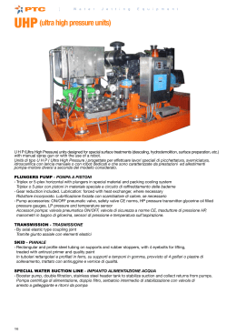
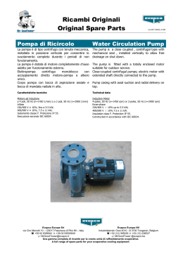
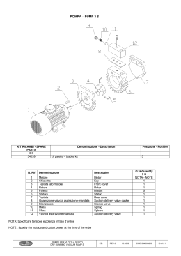
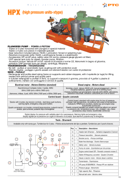
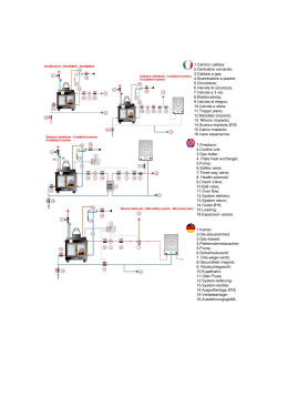
ISTRUZIONI PER L'INSTALLAZIONE E LA MANUTENZIONE
INSTRUCTIONS FOR INSTALLATION AND MAINTENANCE
GRUPPI ANTINCENDIO
A NORME UNI 9490 – UNI 10779
E
GRUPPI ANTINCENDIO
A NORME UNI 9490
CON MOTOPOMPA DIESEL
PER ALIMENTAZIONI IDRICHE
DI IMPIANTI AUTOMATICI ANTINCENDIO
FIRE-FIGHTING SETS
ACCORDING TO STANDARDS UNI 9490 – UNI 10779
AND
FIRE-FIGHTING SETS ACCORDING TO STANDARDS
UNI 9490 WITH DIESEL MOTOR PUMP
FOR SUPPLYING WATER
TO AUTOMATIC FIRE-FIGHTING SYSTEMS
DICHIARAZIONI DI CONFORMITÀ :
MARCATURA CE
La Ditta DAB PUMPS s.p.a. - Via M. Polo,14 - Mestrino (PD) - ITALY - sotto la propria esclusiva responsabilità dichiara
che i prodotti sotto menzionati sono conformi a:
− Direttiva del Consiglio del 14 giugno 1989 n° 89/392 concernente il riavvicinamento delle legislazioni degli Stati membri
CEE relative alle macchine e successive modifiche.
− Direttiva della Compatibilità elettromagnetica 89/336 e successive modifiche.
− Direttiva Bassa Tensione 73/23 e successive modifiche.
NORMATIVA UNI 9490/10779 ANTINCENDIO
Si dichiara che il gruppo d’alimentazione idrica per impianto antincendio sotto riportato è stato fornito in conformità alla
normativa UNI 9490/10779 per quanto concerne i componenti idraulici e loro disposizione e le apparecchiature di comando
e controllo.
DECLARATION OF CONFORMITY :
CE MARKING
The company DAB PUMPS s.p.a. – Via M. Polo, 14 – Mestrino (PD) – ITALY – declares under its own exclusive
responsibility that the products specified below comply with:
− Council Directive of 14 June 1989 n° 89/392 concerning the approximation of the laws of the EEC member states relating
to machinery and later amendments.
− Directive on Electromagnetic Compatibility 89/336 and later amendments.
− Directive on Low Voltage 73/23 and later amendments.
STANDARD UNI 9490/10779 FIRE-FIGHTING
This is to declare that the water supply group for a fire-fighting system specified below has been supplied in conformity with
standard UNI 9490/10779 as concerns its hydraulic components and their location and the command and control equipment.
Mestrino (PD), 22/04/2002
Attilio Conca
Legale Rappresentante
Legal Representative
ITALIANO
GRUPPO ANTINCENDIO A NORME UNI 9490 – UNI 10779
E
GRUPPO ANTINCENDIO A NORME UNI 9490 CON MOTOPOMPA DIESEL
COLLETTORE D’UNIONE MOTOPOMPA DIESEL
AD ELETTROPOMPA
5
7
2
17
14
6
1
2
6
10
3
3
A
12
11
4
4
B
13
B
15
16
9
8
P2
A
Attacco per serbatoio adescamento
1
Da collegare al fondo del serbatoio d’adescamento 2
a mezzo valvola di ritegno.
3
SOLO PER INSTALLAZIONI
P3
Quadro elettrico pompa Pilota
Quadro elettrico elettropompa
Valvola di non ritorno ispezionabile
SOPRABATTENTE.
B
Valvola di controllo valvola non ritorno
Da collegare allo scarico
PER INSTALLAZIONI
SOPRABATTENTE E SOTTOBATTENTE
4
Diaframma ricircolo acqua da collegare:
− alla sommità del serbatoio di adescamento per
installazioni soprabattente.
− alla sommità della riserva idrica per
installazioni sottobattente.
5
Pressostato avviamento pompa principale
6
Collettore di mandata
7
Vaso di espansione a membrana
10 Misuratore di portata
OPTIONAL
11 Manovuotometro
12 Valvola di prova manuale
13 Giunto antivibrante Motopompa Diesel
P1 Elettropompa principale
14 Quadro elettrico Motopompa Diesel
P2 Motopompa Diesel principale
15 Serbatoio Motopompa Diesel
P3 Pompa Pilota
16 Batterie d’avviamento Motopompa Diesel
17 Motore Diesel
1
P1
ITALIANO
GRUPPO ANTINCENDIO UNI 9490 – UNI 10779
COLLETTORE DI MANDATA
ALL’IMPIANTO
SCHEMA IDRAULICO ALIMENTAZIONE SOTTOBATTENTE
SCARICO
IMPIANTO
* Componenti e materiale a cura dell’installatore
P1 Pompa di alimentazione n.1
P2 Pompa di alimentazione n.2 (Motopompa Diesel)
P3 Pompa pilota
Saracinesca aspirazione pompe di alimentazione P1 e P2
1*
Saracinesca aspirazione pompa pilota
1
Manovuotometro
2
Valvola intercettazione manovuotometro
3
Diaframma ricircolo acqua
4
Valvola di non ritorno ispezionabile
5
Valvola in mandata
6
Valvola di scarico impianto
7*
Valvola di scarico impianto
8*
Valvola di prova manuale
9
Manometro
11
2
12*
13
14*
15*
16*
17
18
19
20*
21*
22
23
24
100
Valvola d’intercettazione
Vaso di espansione a membrana
Misuratore di portata
Filtro aspirazione
Riserva idrica
Pressostato avviamento pompa n.1
Pressostato avviamento pompa n.2
Pressostato pompa pilota
Tubazione per il ricircolo
Tubazione scarico impianto
Pressostato pompa in moto
Valvola intercettazione vaso a membrana
Valvola non ritorno circuito di prova manuale
Elettrovalvola di scarico prova settimanale
ITALIANO
GRUPPO ANTINCENDIO UNI 9490 – UNI 10779
COLLETTORE DI MANDATA
TUBAZIONE PER IL RICIRCOLO
ALL’IMPIANTO
SCHEMA IDRAULICO ALIMENTAZIONE SOPRABATTENTE
TUBAZIONE ADESCAMENTO
* Componenti e materiale a cura dell’installatore
P1 Pompa di alimentazione n.1
P2 Pompa di alimentazione n.2 (Motopompa Diesel)
P3 Pompa pilota
Manovuotometro
2
Valvola intercettazione manovuotometro
3
Diaframma ricircolo acqua
4
Valvola di non ritorno ispezionabile
5
Valvola in mandata
6
Valvola di scarico impianto
7*
Valvola di scarico impianto
8*
Valvola di prova manuale
9
10* Valvola di fondo
Manometro
11
Valvola d’intercettazione
12
Vaso di espansione a membrana
13
Misuratore di portata
14
15* Filtro aspirazione
16* Riserva idrica
17
18
19
20*
21*
22
23
24
25*
26*
27*
28*
29*
30*
31*
32*
100
3
Pressostato avviamento pompa n.1
Pressostato avviamento pompa n.2
Pressostato pompa pilota
Tubazione per il ricircolo
Tubazione scarico impianto
Pressostato pompa in moto
Valvola intercettazione vaso a membrana
Valvola non ritorno circuito di prova manuale
Valvola intercettazione adescamento
Galleggiante serbatoio adescamento
Valvola a galleggiante
Scarico troppo pieno
Valvola intercettazione
Serbatoio adescamento
Valvola di scarico serbatoio adescamento
Alimentazione serbatoio adescamento
Elettrovalvola di scarico prova settimanale
ITALIANO
1.
2.
2.1.
2.2.
2.3.
3.
4.
5.
6.
6.2.
6.10.
6.11.
6.12.
7.
8.
8.1.
9.
10.
10.2
*
INDICE
GENERALITA’
AVVERTENZE
Personale Tecnico Qualificato
Sicurezza
Responsabilità
INSTALLAZIONE
ALLACCIAMENTO ELETTRICO
COLLEGAMENTI MOTOPOMPA DIESEL
AVVIAMENTO
Operazioni per Motopompa Diesel
Gas di scarico Motopompa Diesel
Aspirazione Aria
Collegamento Motopompa Diesel ad Elettropompa
ISTRUZIONI PER L’ESERCIZIO DEL GRUPPO
REGOLAZIONI DEL GRUPPO
Taratura pressostati
ELETTROPOMPA DI COMPENSAZIONE
MANUTENZIONE
Ricerca e soluzione inconvenienti
VARIANTE GRUPPI DA NORME UNI 9490 A NORME UNI 10779
pag.
4
4
4
4
4
4
5
5
5
5
7
7
7
7
8
8
8
9
9
10
1.
GENERALITÀ
Prima di procedere all’installazione leggere attentamente questa documentazione. L’installazione ed il
funzionamento dovranno essere conformi alla regolamentazione di sicurezza del paese di installazione del
prodotto. Tutta l’operazione dovrà essere eseguita a regola d’arte ed esclusivamente da personale tecnico
qualificato (paragrafo 2.1) in possesso dei requisiti richiesti dalle normative vigenti. Il mancato rispetto delle
norme di sicurezza, oltre a creare pericolo per l’incolumità delle persone e danneggiare le apparecchiature, farà
decadere ogni diritto di intervento in garanzia.
Conservare con cura questo manuale per ogni ulteriore consultazione anche dopo la prima installazione.
2.
2.1.
AVVERTENZE
Personale tecnico qualificato
È indispensabile che l’installazione venga eseguita da personale competente e
qualificato, in possesso dei requisiti tecnici richiesti dalle normative specifiche in
materia.
Per personale qualificato si intendono quelle persone che per la loro formazione, esperienza ed istruzione,
nonché le conoscenze delle relative norme, prescrizioni provvedimenti per la prevenzione degli incidenti e sulle
condizioni di servizio, sono stati autorizzati dal responsabile della sicurezza dell’impianto ad eseguire qualsiasi
necessaria attività ed in questa essere in grado di conoscere ed evitare qualsiasi pericolo. (Definizione per il
personale tecnico qualificato IEC 364)
2.2.
Sicurezza
L’utilizzo è consentito solamente se l’impianto elettrico è contraddistinto da misure di sicurezza secondo le Normative vigenti
nel paese di installazione del prodotto (per l’Italia CEI 64/2).
2.3.
Responsabilità
Il costruttore non risponde del buon funzionamento del gruppo o di eventuali danni da questo
provocato, qualora lo stesso venga manomesso, modificato e/o fatto funzionare fuori dal campo
di lavoro consigliato o senza l’ausilio dei nostri quadri di comando e protezione.
Declina inoltre ogni responsabilità per le possibili inesattezze contenute nel presente manuale
istruzioni, se dovute ad errori di stampa o di trascrizione. Si riserva il diritto di apportare ai
prodotti quelle modifiche che riterrà necessarie od utili, senza pregiudicarne le caratteristiche
essenziali.
3.
3.1.
INSTALLAZIONE
Il gruppo deve essere installato in luogo ben aereato, protetto dalle intemperie, e con temperatura
ambiente non inferiore ai 4°C (10°C nel caso fossero installate anche motopompe), e non superiore ai
40°C.
Posizionare il gruppo in maniera che eventuali operazioni di manutenzione possano essere effettuate
senza difficoltà.
4
ITALIANO
Accertarsi che le tubazioni dell’impianto siano supportate in maniera autonoma e non gravino col proprio
peso sui collettori del gruppo per evitare deformazioni o rotture di qualche suo componente.
3.2
3.3
E' consigliabile collegare i collettori all'impianto interponendo dei giunti antivibranti.
3.4
Assicurarsi che le caratteristiche della fonte di alimentazione idrica siano tali da garantire sempre il prelievo
di portata richiesto nelle condizioni d’esercizio previste.
3.5
Realizzare il tratto aspirante seguendo tutti quegli accorgimenti necessari a rendere minime le perdite di carico e ad
evitare il formarsi di sacche d’aria, come:
a) Posizionare il gruppo il più vicino possibile alla fonte di alimentazione.
b) Dotare ciascuna pompa di una propria condotta di aspirazione (UNI 9490 – 4.9).
c) Posare le tubazioni aspiranti orizzontalmente o con pendenza leggermente ascendente verso il gruppo.
d) Evitare di impiegare gomiti o raccordi che provochino brusche variazioni di direzione. Se necessario usare curve ad
ampio raggio.
e)
Evitare in aspirazione l’effetto “sifone”: rischio di disinnesco delle pompe!
4.
ALLACCIAMENTO ELETTRICO
ATTENZIONE: OSSERVARE LE NORME DI SICUREZZA VIGENTI
4.1.
L’allacciamento elettrico deve essere effettuato esclusivamente da personale specializzato e
qualificato (vedi punto 2.1) in osservanza alle Norme di sicurezza in vigore nel paese di
installazione del prodotto.
4.2.
Controllare tensione e frequenza di alimentazione. Valori difformi a quelli di targa del motore potrebbero
danneggiarlo irrimediabilmente.
4.3.
Eseguire l'allacciamento dei fili del cavo di alimentazione alla morsettiera del quadro di comando, dando
priorità al filo di terra.
Per lo schema elettrico del quadro di comando e le relative note informative, vedi documentazione allegata.
5.
COLLEGAMENTI MOTOPOMPA DIESEL
Collegare i due cavi con coprimorsetto rosso ai poli positivi delle due batterie di avviamento motopompa Diesel, utilizzando
gli appositi morsetti in dotazione.
DA QUESTO MOMENTO LA MOTOPOMPA DIESEL PUO’ AVVIARSI IN MODO
AUTOMATICO PER ABBASSAMENTO PRESSIONE IMPIANTO !!! TENERE IL
SELETTORE DEL QUADRO MOTOPOMPA IN POSIZIONE AZZERAMENTO - 0 .
6.
AVVIAMENTO
Per un corretto avviamento del gruppo, eseguire la seguente procedura seguendo la sequenza sotto indicata:
Eseguire le seguenti operazioni senza dare tensione al quadro.
6.1. Controllare che le parti rotanti ruotino liberamente. A tale scopo togliere il copriventola e, se necessario, la ventola;
quindi ruotare l’albero con un opportuno attrezzo (cacciavite, chiave prussiana, ecc.).
6.2. OPERAZIONI PER MOTOPOMPA DIESEL
Rifornire il serbatoio Diesel con gasolio fino al massimo livello ( garantite 6 ore di autonomia come richiesto da norme
UNI 9490).
Il filtro dell’aria và riempito a livello con apposito olio.
Verificare il livello dell’olio lubrificazione motore tramite apposita astina.
5
ITALIANO
6.3. Adescare il gruppo come segue:
Versare lentamente acqua pulita attraverso uno dei manicotti del tronchetto installato direttamente sulla bocca di
mandata di ogni pompa, fino alla fuoriuscita dell'acqua dal tappo di carico della pompa preventivamente rimosso.
6.4. Montare gli aquabox sugli appositi manicotti del collettore di mandata.
6.5. Inserire in tutti i selettori a chiave dei quadri elettrici le rispettive chiavi posizionate all’interno dello stesso; dopodiché
controllare che tutti i selettori dei quadri siano in posizione “0” .
6.6. Dare tensione ai quadri portando l’interruttore generale forza motrice QS1 in posizione “1”.
La spia verde accesa indica la tensione corretta nel quadro.
6.7.
Controllare il giusto senso di rotazione di ogni pompa.
Avviare per qualche istante la pompa portando il selettore di comando AUT-O-MAN in “MAN” e
verificare se, osservando dal lato ventola, la rotazione del motore avviene in senso orario.
In caso contrario scambiare tra loro nella morsettiera del quadro, due fili qualsiasi di alimentazione
L1-L2-L3 (solo elettropompe).
Prima dell’ avviamento motopompa Diesel, posizionare l’interruttore generale quadro motopompa su I e
lasciare riscaldare l’olio motore fino allo spegnimento della spia N “temperatura olio insufficiente” posta sul
quadro avvio motopompa.
Questa operazione permette al motore Diesel di funzionare con olio già in temperatura .
6.8. Mettere in pressione l’impianto come segue:
posizionare tutti i selettori AUT-O-MAN di ogni pompa principale in “AUT”.
In tal modo, le pompe si metteranno in funzione e continueranno a funzionare finchè non vengono arrestate
manualmente ( tramite il pulsante “ARRESTO”) *VEDI VARIANTE UNI 10779.
6.9. ESECUZIONE COLLAUDO
Per un corretto collaudo del gruppo pompe eseguire la procedura seguendo la sequenza sotto indicata ( previo collaudo
generale dell’impianto come indicato dalla norma UNI 9490 7.2 ).
PROVA DELLA/E POMPA/E ( come da UNI 9490 7.2.1.8 ).
ESEGUIRE QUESTA PROVA CONSIDERANDO UNA POMPA ALLA VOLTA COL RELATIVO QUADRO
DI COMANDO.
a) Con il selettore del quadro in posizione AUT, simulare la caduta pressione nell’impianto tramite apertura della
valvola di prova manuale ( posizione n. 12 a pag. 1 ).
La pompa sotto prova deve avviarsi AUTOMATICAMENTE.
Alla chiusura della valvola di prova manuale, la pompa deve essere fermata MANUALMENTE tramite il
pulsante Arresto – Stop ( UNI 9490 4.9.3.4. ).
( Vedere variante UNI 10779 – solo per impianti ad idranti ).
La prova a) deve essere eseguita TRE volte consecutive per ciascuna elettropompa e/o motopompa Diesel
principale ( ad esclusione dell’elettropompa pilota che si avvia e si arresta AUTOMATICAMENTE ).
b) Con il selettore del quadro in posizione AUT, aprire l’erogazione alla mandata impianto per verificare il
funzionamento ininterrotto alla portata nominale di ciascuna/e pompa/e; non devono verificarsi surriscaldamenti
e/o sovraccarichi.
Alla chiusura dell’erogazione alla mandata impianto la pompa deve essere fermata MANUALMENTE tramite il
pulsante Arresto – Stop ( UNI 9490 4.9.3.4. ).
( Vedere variante UNI 10779 – solo per impianti ad idranti ).
c) Con il selettore del quadro in posizione AUT, aprire la valvola di prova immediatamente dopo la prova b); la
pompa sotto prova deve riavviarsi AUTOMATICAMENTE.
Alla chiusura della valvola di prova, la pompa deve essere fermata MANUALMENTE.
d) Prova segnalazioni di allarme
Ogni caduta di pressione nell’impianto tale da provocare l’avviamento di una o più elettro / motopompe, aziona un
segnale acustico e luminoso da posizionarsi in un locale permanentemente controllato ( UNI 9490 4.9.3.4. ).
Per le elettropompe la mancanza di tensione alimentazione e/o di una fase ( tensione non corretta ) aziona un
segnale acustico e luminoso da posizionarsi in un locale permanentemente controllato ( UNI 9490 4.9.4.5. ).
I segnalatori di allarme sono alimentati da batteria 12v, con capacità sufficiente ad azionare il segnale di allarme per
almeno 24 ore.
Per il collegamento specifico dei segnali di allarme vedere le istruzioni più dettagliate dei quadri elettrici DAB ( è
possibile usufruire di contatti senza potenziale, da portare a distanza, oppure utilizzare gli stessi per comandare il
segnalatore di allarme acustico 12v. ).
6
ITALIANO
6.10. GAS DI SCAPPAMENTO MOTOPOMPA DIESEL
a) I gas di scappamento devono essere scaricati all’esterno del locale del motore tramite condotta
munita di adeguato silenziatore (già incorporato nel Gruppo Motopompa Diesel DAB).
b) Il diametro della condotta deve essere uguale o maggiore del diametro del tubo silenziatore. Ogni
10 metri di condotta, aumentare il diametro del 10%.
c) La contropressione allo scarico non deve essere maggiore del valore specificato dal costruttore ( in
media 600 mm colonna H2O = 0,058 bar ).
d) Devono essere adottati provvedimenti atti ad impedire la ricaduta della condensa nel motore stesso
( es. pozzetto di scarico condensa ).
6.11. ASPIRAZIONE ARIA
La Motopompa Diesel deve essere installata in un luogo ben aereato, protetto dalle intemperie, con
temperatura ambiente non inferiore a 4° C e non superiore a 40° C.
6.12. COLLEGAMENTO MOTOPOMPA DIESEL AD ELETTROPOMPA ( vedi schema pag. 1 )
I Gruppi Antincendio 2 KDN/P… ( elettropompa + motopompa Diesel ), vengono forniti in DUE unità
separate, con collettori di mandata collegabili tra loro tramite un “collettore di unione” incluso nel
gruppo.
7.
7.1.
7.2.
7.3.
7.4.
7.5.
ISTRUZIONI PER L’ESERCIZIO DEL GRUPPO
Ogni pompa del gruppo non dovrebbe essere soggetta a più di 20 avviamenti/h per non sottoporre il
motore ad eccessive sollecitazioni termiche.
Qualora il gruppo dovesse restare per lunghi periodi inattivo, procedere periodicamente ad avviamenti
manuali dello stesso per verificare lo stato di efficienza.
Quando il gruppo rimane per lunghi periodi inattivo a temperatura inferiore a 0 °C , è necessario
procedere al completo svuotamento dello stesso.
Controllare almeno ogni 4-6 mesi ad impianto scarico, la precarica degli aquabox, verificando che sia
mantenuta 0.2 – 0.3 bar inferiore alla più bassa tra le pressioni di partenza delle pompe.
La frequenza di tale controllo deve essere comunque incrementata tanto più quanto maggiore è la
frequenza degli avviamenti e la massima pressione d'esercizio del gruppo.
Verificare periodicamente il livello dell’elettrolito e lo stato di efficienza delle due batterie avviamento
della motopompa Diesel.
7.6. ISPEZIONI PERIODICHE
Ogni impianto deve essere sottoposto, almeno DUE volte all’anno, con intervallo non inferiore a 5 mesi, ad
un’ispezione allo scopo di verificarne lo stato di efficienza e la conformità alla norma UNI 9490.
L’accertamento sarà formalizzato nell’apposito registro ( per maggiori dettagli vedere la norma UNI 9490 8.1. ).
7.7. OPERAZIONI COMUNI ( UNI 9490 8.1.2.1. )
a) Esame generale dell’intero impianto.
b) Rilevamento pressioni in uscita e prova di funzionamento di eventuali segnalatori di allarme.
c) Prova di tenuta di tutte le valvole di non ritorno ( posizione B pag. 1 )
d) Controllo posizione di apertura delle valvole di intercettazione e relativo bloccaggio.
7.8. OPERAZIONI PER POMPE ( UNI 9490 8.1.2.3. )
a) Verifica dello stato delle vasche o dei serbatoi.
b) Verifica del livello dei dispositivi di controllo ed eventuali regolatori di livello dei serbatoi di adescamento.
c) Prova di avviamento automatico e funzionamento delle pompe ( vedi punti 6.9 a) e 6.9 b) ).
d) Prova di riavviamento automatico ( vedi punto 6.9 c) ).
e) Verifica del livello dell’olio lubrificante nel motore, dell’olio del carburante e dell’elettrolita nelle batterie.
7
ITALIANO
8.
REGOLAZIONI DEL GRUPPO
8.1. TARATURA PRESSOSTATI
Qualora si voglia ottenere una taratura dei pressostati diversa da quella eseguita in Sede, durante il collaudo del gruppo
di pompaggio, agire secondo le seguenti istruzioni considerando:
- il tipo di pressostato installato nel gruppo di pompaggio;
- i limiti di pressione indicati sulle targhette dati di ogni pompa.
il limite indicato dalla norma UNI 9490 – 4.9 per cui il pressostato deve essere tarato in modo da avviare la pompa
quando la pressione a valle si è ridotta ad un valore compreso tra il 75 e l’85% di quella prodotta dalla pompa
funzionante a mandata chiusa.
Pressostato Telemecanique tipo XMP
Allentare la vite nera e togliere il coperchio.
Girando in senso orario la vite metallica “A” posizionata al centro
del pressostato, vengono incrementate contemporaneamente le
pressioni di partenza e d’arresto della pompa.
Girando in senso antiorario vengono decrementate.
Girando in senso orario la vite nera “B” posizionata all’estremità
del pressostato viene incrementato il differenziale tra la pressione
di partenza e quella d’arresto della pompa (la pressione di
partenza diminuisce mentre quella d’arresto rimane fissa).
Girando in senso antiorario il differenziale viene decrementato.
Rimettere il coperchio e avvitare la vite nera.
Pressostato Klockner Moeller tipo MCS
Allentare le 4 viti e togliere il coperchio trasparente.
Svitare e togliere la vite di bloccaggio “B” posizionata in uno dei
12 fori della manopola di taratura “A”. (figura 1)
Ruotando la manopola di taratura “A” in senso orario vengono
incrementate contemporaneamente le pressioni di partenza e
d’arresto della pompa.
Girando in senso antiorario vengono decrementate. (figura 2)
Premendo la manopola di taratura “A” e ruotandola in senso
antiorario viene incrementato il differenziale tra la pressione di
partenza e quella d’arresto della pompa (la pressione di partenza
diminuisce mentre quella d’arresto rimane fissa).
Premendo la manopola di taratura “A” e ruotandola in senso orario
il differenziale viene decrementato. (figura 3)
Rimettere e fissare la vite di bloccaggio “B” nel foro della
manopola di taratura “A” che più sia allineato con uno dei due
filetti sottostanti la manopola stessa. (figura 4)
Rimettere il coperchio trasparente e avvitare le 4 viti.
Una volta ritarati i pressostati, per controllarne i nuovi valori delle pressioni di partenza ed arresto
delle pompe del gruppo di pompaggio, eseguire il procedimento “Controllo della pressione di
chiusura dei pressostati di comando" (vedi punto 6.9.).
9.
ELETTROPOMPA DI COMPENSAZIONE
9.1. I gruppi di pompaggio possono essere forniti con una pompa di compensazione autoadescante, modelli JET, collegata
al collettore di mandata mediante una valvola di ritegno a clapet ed una valvola d'intercettazione a sfera.
L’aspirazione invece, come per qualsiasi pompa di un gruppo a norme UNI 9490, viene mantenuta indipendente.
9.2.
Mantenere il pressostato di comando della pompa di compensazione sempre tarato con pressioni di
partenza ed arresto maggiore degli altri. Ciò è indispensabile ai fini di permettere a tale pompa di
svolgere la sua funzione di compensazione dei piccoli abbassamenti di pressione dell'impianto prima
di far avviare le elettropompe e la motopompa principali.
8
ITALIANO
10.
MANUTENZIONE
10.1. Tutti i nostri gruppi sono sottoposti ad un rigoroso collaudo sia della parte elettrica che della parte idraulica.
Difficilmente possono manifestarsi difetti di funzionamento, se non per cause esterne o del tutto accidentali.
10.2. Viene riportata di seguito una tabella con alcuni suggerimenti riguardanti la messa a punto del gruppo nel caso di
irregolarità di funzionamento.
INCONVENIENTI
UNA POMPA DEL GRUPPO
NON SI ADESCA.
UNA POMPA DEL GRUPPO
NON SI AVVIA.
IL PULSANTE D’ARRESTO
NON FERMA LA POMPA
IL GRUPPO NON FORNISCE
LE CARATTERISTICHE
RICHIESTE.
CAUSE POSSIBILI
RIMEDI
1. Condotto di aspirazione di diametro
insufficiente; eccessivo impiego di raccordi
che provochino brusche variazioni di
direzione del condotto aspirante; effetto
sifone.
2. Condotto di aspirazione intasato.
3. Infiltrazioni d'aria nel condotto aspirante della
pompa.
1.
Controllare che il condotto di aspirazione
sia realizzato correttamente, secondo
quanto
indicato
nel
paragrafo
"Installazione".
2.
3.
4. Valvola di fondo intasata o bloccata.
5. Valvola d'intercettazione in aspirazione
parzialmente chiusa.
4.
5.
Pulirlo o sostituirlo.
Controllare, mediante prova a pressione,
la perfetta tenuta nei raccordi, nelle
giunzioni, nelle tubazioni.
Pulirla o sostituirla.
Aprirla completamente.
1. Interruttore generale forza motrice e/o
interruttore generale circuito ausiliario
disinseriti (in posizione "0").
2. Interruttori magnetotermici di protezione del
trasformatore e/o del circuito ausiliario
difettosi o intervenuti.
3. Le batterie di avviamento motopompa Diesel
non sono efficienti.
1.
4. Circuito elettrico interrotto.
4.
1. Importanti perdite d'acqua nell'impianto, per
cui la pressione non si ristabilisce al di sopra
della pressione di apertura del pressostato
(circa 1,5 bar al di sopra della pressione di
chiusura del pressostato, cioè di partenza
dell’elettropompa e della motopompa).
2. E’ stato inserito un ponte nei morsetti per il
collegamento del galleggiante per il serbatoio
di adescamento (da installare nel caso di
aspirazione soprabattente)
1.
Controllare le giunzioni, i raccordi, i tubi.
2.
3. L’elettrovalvola non si è chiusa al termine
della prova settimanale ( gruppi con prova
settimanale – solo per elettropompa ).
3.
Togliere il ponte nel caso di aspirazione
sottobattente.
Inserire il galleggiante per il serbatoio di
adescamento nel caso di aspirazione
soprabattente.
Controllare
l’elettrovalvola,
ed
eventualmente pulirne il filtro.
1.
1.
3.
Scelta di un gruppo sottodimensionato
rispetto alle caratteristiche dell'impianto.
Eccessivo consumo d'acqua rispetto alla
portata fornibile dalla fonte di alimentazione
idrica (serbatoio, pozzo, acquedotto,ecc.)
Senso di rotazione dei motori inverso.
4.
Una o più pompe si sono intasate.
4.
5.
6.
Tubazioni intasate.
Valvole di fondo intasate o bloccate (gruppo
soprabattente).
Valvole d'intercettazione in aspirazione e
mandata parzialmente chiuse.
Infiltrazioni d'aria nei condotti aspiranti delle
pompe del gruppo.
5.
6.
Cambiarlo
eseguendo
l'operazione
riportata nel punto 6.7. del paragrafo
"Avviamento".
Smontarle e pulire il corpo pompa e le
giranti, assicurandosi del loro buono
stato.
Pulirle o sostituirle.
Pulirle o sostituirle.
7.
Aprirle completamente.
8.
Controllare, mediante prova a pressione la
perfetta tenuta nei raccordi, nelle
giunzioni, nelle tubazioni.
2.
7.
8.
9
2.
3.
2.
3.
Inserirli portandoli in posizione "1" e
verificare che si accendano le due spie
verdi di tensione corretta nel quadro.
Se difettosi, sostituirli.
Se intervenuti, reinserirli.
Controllare l’efficienza dei caricabatterie
posti nel quadro motopompa (controllo
assorbimenti tramite amperometri del
quadro motopompa)
Se le batterie sono inefficienti , sostituirle.
Ricercare con un tester il punto
d'interruzione, e ripararlo.
Sostituirlo con uno adatto alle
caratteristiche richieste.
Aumentare la portata fornibile dalla fonte
di alimentazione idrica.
ITALIANO
INCONVENIENTI
CAUSE POSSIBILI
UNA O PIU' POMPE DEL
GRUPPO, QUANDO
VENGONO FERMATE,
GIRANO IN SENSO
INVERSO.
1.
UNA POMPA DEL GRUPPO
DOPO ESSERE STATA
ARRESTATA, NON
RIPARTE.
IL MOTORE DI UNA
ELETTROPOMPA DEL
GRUPPO VIBRA.
RIMEDI
Le relative valvole di non ritorno o di fondo
non chiudono bene o sono bloccate.
La relativa condotta di aspirazione è a tenuta
non stagna.
1.
1.
2.
Fusibili di protezione del motore bruciati.
Alla bobina del relativo teleruttore non arriva
corrente.
1.
2.
3.
4.
3.
4.
5.
Bobina del teleruttore interrotta.
Al relativo pressostato di comando non arriva
la pressione dell'impianto.
Pressostato di comando in avaria.
1.
2.
Un fusibile di protezione del motore bruciato.
Base portafusibili allentata o difettosa.
1.
2.
3.
Contatti del relativo teleruttore logori o
difettosi.
Pompa bloccata.
Cuscinetti logori.
Cavi elettrici spezzati.
3.
Sostituirlo.
Fissarla se allentata. Sostituirla se
difettosa.
Sostituire il teleruttore.
4.
5.
6.
Sbloccarla.
Sostituirli.
Controllarli e ripararli.
2.
4.
5.
6.
2.
5.
Verificarne la tenuta ed il corretto
funzionamento.
Verificarne la tenuta mediante prova a
pressione.
Sostituirli.
Controllare con un tester il circuito
elettrico fino alla bobina stessa, e
riparare
l'eventuale
interruzione
riscontrata.
Sostituirla.
Toglierlo e pulire il manicotto di
collegamento.
Sostituirlo.
* VARIANTE GRUPPI DA NORME UNI 9490 A NORME UNI 10779.
La norma UNI 10779, che viene applicata esclusivamente per impianti con idranti, ammette l’arresto
AUTOMATICO delle pompe principali dopo che la pressione nell’impianto “ si sia mantenuta al di sopra
della pressione di avviamento della pompa stessa per almento 20 minuti consecutivi”
In pratica, dopo 20 minuti dalla chiusura degli idranti, la pompa può arrestarsi automaticamente.
Tutti i gruppi con pompe serie 1 – 2 KDN/P … M.D.UNI sono facilmente trasformabili da gruppi UNI
9490 (ARRESTO SOLO MANUALE) in gruppi UNI 10779 (ARRESTO AUTOMATICO) tramite il
selettore SA2 posto all’interno dei quadri di comando delle pompe principali ( per le relative note
informative vedi Libretto Istruzione del Quadro Elettrico ).
10
ENGLISH
FIRE-FIFHTING SETS ACCORDING TO STANDARDS UNI 9490 – UNI 10779
AND
FIRE-FIGHTING SETS ACCORDING TO STANDARDS UNI 9490
WITH DIESEL MOTOR PUMP
MANIFOLD JOINING THE DIESEL MOTOR PUMP
TO THE ELECTROPUMP
5
7
2
17
14
6
1
2
6
10
3
3
A
12
11
4
4
B
13
B
15
16
9
8
P3
P2
A
Coupling for priming tank
1
To be connected to the bottom of the priming tank 2
with a check valve.
3
ONLY FOR INSTALLATIONS
P1
Pilot pump electric panel
Electropump electric panel
Inspectable non-return valve
ABOVE HEAD
B
Non-return valve control valve
To be connected to the discharge
FOR INSTALLATIONS
ABOVE HEAD AND BELOW HEAD
4
Water recycling diaphragm to be connected:
− to the top of the priming tank for installations
above head.
− to the top of the water reserve for
installations below head.
5
Main pump starting pressure switch
6
Delivery manifold
7
Membrane expansion tank
10 Flow rate meter
OPTIONAL
11 Vacuum pressure gauge
12 Manual test valve
13 Diesel motor pump vibration-damping joint
P1 Main electropump
14 Diesel motor pump electric panel
P2 Main Diesel motor pump
15 Diesel motor pump tank
P3 Pilot pump
16 Diesel motor pump starting batteries
17 Diesel motor
11
ENGLISH
FIRE-FIGHTING SETS ACCORDING TO STANDARDS UNI 9490 – UNI 10779
DELIVERY MANIFOLD
SYSTEM
DISCHARGE
* Components and material attended to by the installer
P1 Feeding pump no. 1
P2 Feeding pump no. 2 (Diesel motor pump)
P3 Pilot pump
Feeding pumps P1 and P2 intake gate valve
1*
Pilot pump intake gate valve
1
Vacuum pressure gauge
2
Vacuum pressure gauge interception valve
3
Water
recycling diaphragm
4
Inspectable non-return valve
5
Valve on suction
6
Discharge valve
7*
System discharge valve
8*
Manual test valve
9
Pressure
switch interception valve
10
Pressure gauge
11
12
12*
13
14*
15*
16*
17
18
19
20*
21*
22
23
24
100
Interception valve
Membrane expansion tank
Flow rate meter
Suction filter
Water reserve
Pump no. 1 starting pressure switch
Pump no. 2 starting pressure switch
Pilot pump pressure switch
Recycling pipe
Discharge pipe
Running pump pressure switch
Membrane tank interception valve
Manual test circuit non-return valve
Weekly test discharge electrovalve
TO THE SYSTEM
HYDRAYLIC DIAGRAM FOR FEED BELOW HEAD
ENGLISH
FIRE-FIGHTING SETS ACCORDING TO STANDARDS UNI 9490 – UNI 10779
DELIVERY MANIFOLD
RECYCLING PIPE
TO THE SYSTEM
HYDRAULIC DIAGRAM FOR FEED ABOVE HEAD
PRIMING PIPE
* Components and material attended to by the installer
P1 Feeding pump no. 1
P2 Feeding pump no. 2 (Diesel motor pump)
P3 Pilot pump
Vacuum pressure gauge
2
Vacuum pressure gauge interception valve
3
Water recycling diaphragm
4
Inspectable non-return valve
5
Valve on suction
6
Discharge valve
7*
System discharge valve
8*
Manual test valve
9
10* Foot valve
Pressure gauge
11
Interception valve
12
Membrane expansion tank
13
Flow rate meter
14
15* Suction filter
16* Water reserve
13
17
18
19
20*
21*
22
23
24
25*
26*
27*
28*
29*
30*
31*
32*
100
Pump no. 1 starting pressure switch
Pump no. 2 starting pressure switch
Pilot pump pressure switch
Recycling pipe
Discharge pipe
Running pump pressure switch
Membrane tank interception valve
Manual test circuit non-return valve
Priming interception valve
Priming tank float
Float valve
Overflow pipe
Interception valve
Priming tank
Priming tank discharge valve
Priming tank feed
Weekly test discharge electrovalve
ENGLISH
1.
2.
2.1.
2.2.
2.3.
3.
4.
5.
6.
6.2.
6.10.
6.11.
6.12.
7.
8.
8.1.
9.
10.
10.2
*
CONTENTS
GENERAL
WARNINGS
Skilled technical personnel
Safety
Responsibility
INSTALLATION
ELECTRICAL CONNECTION
DIESEL MOTOR PUMP CONNECTIONS
STARTING UP
Operations for Diesel motor pump
Diesel motor pump exhaust gas
Air intake
Connection of Diesel motor pump to Electropump
INSTRUCTIONS FOR RUNNING THE SET
REGULATING THE SET
Calibration of the pressure switches
COMPENSATING ELECTROPUMP
MAINTENANCE
Troubleshooting
VARIATION FOR SETS FROM STANDARDS UNI 9490 - TO
STANDARDS UNI 10779
pag.
14
14
14
14
14
14
15
15
15
15
17
17
17
17
18
18
19
19
17
20
1.
GENERAL
Read this documentation carefully before installation. Installation and functioning must comply with the
safety regulations in force in the country in which the product is installed. The entire operation must be carried
out in a workmanlike manner and exclusively by skilled technical personnel (paragraph 2.1.) in possession of the
qualifications requested by the regulations in force. Failure to comply with the safety regulations not only causes
risk to personal safety and damage to the equipment, but invalidates every right to assistance under guarantee.
Keep this manual with care for further consultation even after the first installation.
2.
2.1.
WARNINGS
Skilled technical personnel
It is indispensable that installation be carried out by competent, skilled personnel in possession of the
technical qualifications required by the specific legislation in force.
The term skilled personnel means persons whose training, experience and instruction, as well as their
knowledge of the respective standards and requirements for accident prevention and working conditions, have
been approved by the person in charge of plant safety, authorizing them to perform all the necessary activities,
during which they are able to recognize and avoid all dangers. (Definition for technical personnel IEC 364).
2.2.
Safety
Use is allowed only if the electric system is in possession of safety precautions in accordance with the regulations in force in
the country where the product is installed (for Italy, IEC 64/2).
2.3.
Responsibility
The Manufacturer does not vouch for correct operation of the set or for any damage that it may
cause if it has been tampered with, modified and/or run outside the recommended work range or
without the aid of our control and protection panels.
The Manufacturer declines all responsibility for possible errors in this instructions manual, if
due to misprints or errors in copying. The Manufacturer reserves the right to make any
modifications to products that it may consider necessary or useful, without affecting the essential
characteristics.
3.
3.1.
INSTALLATION
The set must be fitted in a well ventilated place, protected from unfavourable weather conditions and with
an environment temperature not lower than 4°C (10°C if also motor pumps are installed), and not
exceeding 40°C.
Position the set in such a way that any maintenance jobs can be carried out without difficulty.
14
ENGLISH
Ensure that the system pipes are independently supported and do not weigh down on the set manifolds so as
to avoid deformation or breaking of any of its components.
3.2
3.3
It is advisable to insert vibration-damping couplings when connecting the delivery manifold to the system.
3.4
Ensure that the characteristics of the water supply source are such as always to guarantee the flow rate
required in the expected operating conditions.
3.5
Make the intake section following all the precautions necessary to keep load losses to a minimum and to avoid the
formation of air pockets, for example:
a) Position the set as close as possible to the water supply source.
b) Provide each pump with its own intake pipe (UNI 9490 - 4.9).
c) Lay the suction pipes horizontally or sloping slightly upwards towards the set.
d) Avoid using elbows or couplings that cause sudden changes in direction. If necessary, use bends with a wide
radius.
e)
Avoid the “siphon” effect at intake: it risks unpriming the pumps!
4.
ELECTRICAL CONNECTION
CAUTION! ALWAYS FOLLOW THE SAFETY REGULATIONS.
4.1.
The electrical installation must be carried out by a qualified, skilled electrician (see point
2.1.) in compliance with the Safety Regulations in force in the country where the product
is installed.
4.2.
Check the power supply voltage and frequency. Values differing from those on the motor plate could
cause irremediable damage.
4.3.
Connect the leads of the power supply cable to the terminal board on the control panel, giving priority to
the earth lead.
For the wiring diagram of the control panel and the respective informative notes, see the enclosed documentation.
5.
DIESEL MOTOR PUMP CONNECTIONS
Connect the two cables with a red terminal cover to the positive poles of the two batteries for starting the Diesel motor pump,
using the special terminals provided.
FROM NOW ON THE DIESEL MOTOR PUMP CAN START AUTOMATICALLY
DUE TO A FALL IN SYSTEM PRESSURE !!! KEEP THE SELECTOR ON THE
MOTOR PUMP PANEL IN ZERO POSITION – 0.
6.
STARTING
To start the set correctly, perform the procedure below following the sequence indicated:
Perform the following operation without switching on the power to the panel.
6.1. Check that the moving parts turn freely. To do this, remove the fan cover and, if necessary, the fan; then turn the shaft
with a suitable tool (screw driver, offset adjustable spanner, etc.).
6.2. OPERATIONS FOR DIESEL MOTOR PUMP
Fill the Diesel tank with diesel fuel up to maximum level (6 hours guaranteed autonomy as required by standards UNI
9490).
The air filter must be filled to the level with special oil.
Check the level of the motor lubrication oil with the dipstick.
15
ENGLISH
6.3. Prime the set as follows:
Slowly pour in clean water through one of the sleeves of the stub pipe installed directly on the delivery aperture of
each pump, until water comes out of the pump filling hole from which the tap has previously been removed.
6.4. Fit the aquaboxes on the special sleeves of the delivery manifold.
6.5. Insert in all the key selectors on the electric panel the respective keys to be found inside it; then check that all the
selectors on the panel are turned to position “0”.
6.6. Switch on the power to the panels by turning the main motive power switch QS1 to position “1” .
When the green warning light comes on it indicates that the panel is live.
6.7.
Check that each pump is turning in the correct direction.
Start the pump for a few moments, turning the AUT-O-MAN control selector to “MAN” and check,
looking from the fan side, whether the motor is turning in a clockwise direction.
If it is turning in the wrong direction, invert on the panel terminal board any two leads of the power cable
L1-L2-L3. (only electropumps).
Before starting the Diesel motor pump, turn the main switch on the motor pump panel to I and let the motor oil
warm up until the “insufficient oil temperature” warning light N on the motor-pump starting panel goes out.
This operation alows the Diesel motor to work with the oil already at working temperature.
6.8. Put the system under pressure as follows:
turn all the AUT-O-MAN control selectors of each main pump to “AUT”.
In this way, the pumps will be started and will continue operating until they are stopped manually (with the “STOP”
button) * SEE VARIATION UNI 10779.
6.9. PERFORMING THE TEST
For correct testing of the pump set, perform the procedure following the sequence indicated below (after general testing
of the system as indicated in standard UNI 9490 7.2 ).
TESTING THE PUMP(S) (according to UNI 9490 7.2.1.8)
PERFORM THIS TEST CONSIDERING ONE PUMP AT A TIME WITH THE RESPECTIVE CONTROL
PANEL.
a) With the selector on the panel in AUT position, simulate a fall in pressure of the system by opening the manual
test valve (position no. 12 on page 1).
The pump being tested must start AUTOMATICALLY.
On closing the manual test valve the pump must be stopped MANUALLY with the Stop button (UNI 9490
4.9.3.4.).
(See variant UNI 10779 – only for systems with hydrants).
The test indicated in point a) must be carried out THREE consecutive times for each main electropump and/or
Diesel motor pump (except the pilot electropump which starts and stops AUTOMATICALLY).
b) With the selector on the panel in AUT position, turn on the water supply to system delivery to check
uninterrupted operation at the nominal flow rate of each pump; there must be no overheating and/or overloads.
When the water supply to system delivery is turned off the pump must be stopped MANUALLY with the Stop
button (UNI 9490 4.9.3.4).
(See variant UNI 10779 – only for systems with hydrants).
c) With the selector on the panel in AUT position, turn on the test valve immediately after test b); the pump being
tested must restart AUTOMATICALLY.
On closing the test valve the pump must be stopped MANUALLY.
d) Testing the alarm signals
Any fall in pressure in the system such as to cause the starting of one or more electropumps/motor pumps activates
an acoustic and luminous signal to be positioned in permanently controlled place (UNI 9490 4.9.3.4.).
For electropumps the lack of power supply and/or of a phase (incorrect voltage) activates an acoustic and luminous
signal to be positioned in permanently controlled place (UNI 9490 4.9.4.5 ).
The alarm signals are fed by a 12V battery, with sufficient capacity to activate the alarm signal for at least 24
hours.
For the specific connection of the alarm signals see the more detailed instructions of DAB electric control panels (it
is possible to use contacts without potential, to be placed at a distance, or to use the same contacts to control the
12V acoustic alarm signal).
16
ENGLISH
6.10. DIESEL MOTOR PUMP EXHAUST GAS
a) The exhaust gases must be discharged outside the room where motor is located by means of a duct
fitted with a suitable silencer (already incorporated in the DAB Diesel Motor pump Set).
b) The diameter of the duct must be equal to or greater than the diameter of the silencer pipe. Every 10
metres of duct, increase the diameter by 10%.
c) The back pressure at discharge must not be greater than the value specified by the manufacturer (on
average 600 mm water column = 0.058 bar).
d) Precautions must be taken to prevent condensate falling into the motor (e.g. condensate discharge pit ).
6.11. AIR INTAKE
The Diesel Motor pump must be installed in a well ventilated place, protected from unfavourable
weather conditions and with an environment temperature not lower than 4°C and not exceeding 40°C.
6.12. CONNECTION OF DIESEL MOTOR PUMP TO ELECTROPUMP (see diagram on page 10)
The Fire-fighting Sets 2 KDN/P… (electropump + Diesel motor pump), are supplied in TWO separate
units, with delivery manifolds that can be connected together by means of a “joining manifold” included
in the set.
7.
7.1.
7.2.
INSTRUCTIONS FOR RUNNING THE SET
Each pump in the set should not be started more than 20 times in one hour to avoid subjecting the motor
to excessive thermal stress.
If the set should remain inactive for long periods, periodically perform manual starting of the set to
check its state of efficiency.
7.3.
When the set remains inactive for long periods at a temperature below 0°C, it must be drained
completely.
7.4.
At least every 4-6 months, with the system empty, check the preloading of the aquaboxes, ensuring that
it remains 0.2-0.3 bar below the lowest of the starting pressures of the pumps.
The frequency of this check must be increased, the more frequent the starts and the greater the maximum
working pressure of the set.
7.5.
Periodically check the level of the electrolyte and the state of efficiency of the two starting batteries of the
Diesel motor pump.
.
7.6. PERIODIC INSPECTIONS
At least TWICE a year, at an interval of no less than 5 months, each system must be inspected in order to check its state
of efficiency and conformity with standard UNI 9490.
The result will be recorded in a special register (for greater details see standard UNI 9490 8.1.).
7.7 COMMON OPERATIONS (UNI 9490 8.1.2.1. )
a) General examination of the entire system.
b) Measurement of pressure at output and test of operation of any alarm signals.
c) Testing the seal of all the non-return valves (position B page 1-2).
d) Checking the opening position of the interception valves and their blocking.
7.8 OPERATIONS FOR PUMPS (UNI 9490 8.1.2.3. )
a) Checking the state of the tanks or reservoirs.
b) Checking the level of the control devices and any level regulators in the priming tanks.
c) Testing automatic starting and operation of the pumps (see points 6.9 a) and 6.9 b)).
d) Testing automatic restarting (see point 6.9 c) ).
e) Checking the level of the lubricating oil in the motor, of the fuel oil and of the electrolyte in the batteries.
17
ENGLISH
8.
REGULATING THE SET
8.1. CALIBRATION OF THE PRESSURE SWITCHES
If you wish to obtain a calibration of the pressure switches different that from that performed in the factory, during
testing of the booster set, follow the instructions below, considering:
−
the type of pressure switch installed in the booster set;
−
the pressure limits indicated on the data plates of each pump.
−
the limit indicated by standard UNI 9490 - 4.9 according to which the pressure switch must be calibrated in such a
way as to start the pump when the pressure downstream has been reduced to a value between 75% and 85% of the
pressure produced by the pump operating with the delivery turned off.
Telemecanique pressure switch type XMP
Slacken the black screw and remove the cover.
When the metal screw “A” in the centre of the pressure switch is
turned clockwise, the pump starting and stopping pressures are
increased at the same time.
When it is turned counter-clockwise they are decreased.
When the black screw “B” at the end of the pressure switch is
turned clockwise, the differential between the starting and the
stopping pressure of the pump is increased (the starting pressure
decreases while the stopping pressure remains fixed).
When it is turned counter-clockwise, the differential is decreased.
Replace the cover and tighten the black screw.
Klockner Moeller pressure switch type MCS
Slacken the 4 screws and remove the transparent cover.
Slacken and remove the locking screw “B” positioned in one of the
12 holes in the regulating knob “A”. (figure 1)
When the regulating knob “A” is turned clockwise, the pump
starting and stopping pressures are increased at the same time.
When it is turned counter-clockwise they are decreased. (figure 2)
When the regulating knob “A” is pressed and turned counterclockwise, the differential between the starting and the stopping
pressure of the pump is increased (the starting pressure decreases
while the stopping pressure remains fixed).
When the regulating knob “A” is pressed and turned clockwise, the
differential is decreased. (figure 3)
Replace and tighten the locking screw “B” in the hole in the
regulating knob “A” that is most aligned with one of the two
threads under the knob. (figure 4)
Fig.1
Fig.2
Replace the transparent cover and tighten the 4 screws.
Fig.4
Fig.3
Once the pressure switches have been recalibrated, to check the new starting and stopping
pressures of the pumps in the booster set, perform the procedure “Checking closing pressure of the
pressure switches" (see point 6.9.).
9.
COMPENSATING ELECTROPUMP
9.1. The booster sets may be supplied with a self-priming compensating pump, JET models, connected to the delivery
manifold by means of a check valve and an interception ball valve.
Instead the suction, as in any pump of a set according to standards 9490, is kept independent.
9.2.
Keep the pressure switch that controls the compensating pump always calibrated with starting and
stopping pressures higher than the others. This is indispensable in order to allow this pump to perform
its task of compensating small falls in pressure in the system before starting the main electropumps and
the motor pump.
18
ENGLISH
10.
MAINTENANCE
10.1. All our sets are subjected to strict testing of both the electrical and the hydraulic part.
It is unusual for malfunctions to occur, unless due to external or completely accidental causes.
10.2. Below is a table with some suggestions on regulating the set in the event of irregularities in operation.
FAULTS
A PUMP IN THE SET DOES
NOT PRIME.
A PUMP IN THE SET DOES
NOT START.
THE STOP BUTTON DOES
NOT STOP THE PUMP
THE SET DOES NOT
SUPPLY THE REQUIRED
CHARACTERISTICS.
POSSIBLE CAUSES
REMEDIES
1. Suction pipe with insufficient diameter;
excessive use of couplings which cause
sudden variations in direction of the suction
pipe; siphon effect.
1.
Check that the suction pipe is correctly
made, as indicated in the paragraph on
"Installation".
2. Suction pipe clogged.
3. Air infiltrations in the suction pipe of the
pump.
2.
3.
4. Foot valve clogged or blocked.
5. Interception valve on suction partly closed.
4.
5.
Clean it or change it.
Testing under pressure, check the perfect
seal in the couplings, the joins and the
pipes.
Clean it or change it.
Open it completely.
1. Main motive power switch and/or main
auxiliary circuit switch off (in position "0").
1.
2. Overload protection switches of the
transformer and/or of the auxiliary circuit
faulty or tripped.
3. The starting batteries of the Diesel motor pump
are not efficient.
2.
4. Electric circuit interrupted.
4.
1. Important water leaks in the system, so the
pressure is not re-established above the
opening pressure of the pressure switch (about
1.5 bar above the closing pressure of the
pressure switch, that is the starting pressure of
the electropump and of the motor pump).
2. A jumper has been fitted on the terminals for
connecting the float for the priming tank (to be
installed in the event of suction above head)
1.
Check the joins, couplings and pipes.
2.
Remove the jumper in the event of
suction below head.
Insert the float for the priming tank in the
event of suction above head.
3. The electrovalve has not closed at the end of
the weekly test (sets with weekly test – only
for electropumps).
3.
Check the electrovalve and clean its filter
if necessary.
1.
1.
Replace it with one that suits the required
characteristics.
Increase the flow rate that can be
supplied by the water supply source.
3.
The set chosen is undersized for the
characteristics of the system
Excessive water consumption for the flow
rate that can be supplied by the water
supply source (tank, well, mains, etc.)
Motors turning in inverse direction
4.
One or more pumps clogged.
4.
5.
6.
Pipes clogged.
Foot valves clogged or blocked (set above
head).
Interception valves at suction and delivery
partly closed.
Air infiltrations in the suction pipe of the
set.
5.
6.
Change it, performing the operation
described in point 6.7. of the paragraph
“Starting up”.
Dismantle them and clean the pump body
and the impellers, ensuring that they are
in good condition.
Clean them or change them.
Clean them or change them.
7.
Open them completely.
8.
Testing under pressure, check the perfect
seal in the couplings, the joins and the
pipes.
2.
7.
8.
19
3.
2.
3.
Switch them on, turning them to position
“1” and check that the green light comes
on indicating that the panel is live.
If faulty, change them.
If tripped, reset them.
Check the efficiency of the battery
chargers in the motor pump panel (check
absorption with the ammeters on the
motor pump panel).
If the batteries are inefficient, change
them.
Use a tester to find the point of
interruption and repair it
ENGLISH
FAULTS
POSSIBLE CAUSES
WHEN STOPPED, ONE OR
MORE PUMPS IN THE SET
TURN IN THE OPPOSITE
DIRECTION.
1.
AFTER BEING STOPPED, A
PUMP IN THE SET DOES
NOT START AGAIN.
.
THE MOTOR OF A PUMP IN
THE SET IS VIBRATING.
REMEDIES
The respective non return or foot valves do
not close well or are blocked.
The respective suction pipe is not
hermetically sealed.
1.
Check its seal and correct operation.
2.
Testing under pressure, check the seal.
1.
2.
Motor protection fuses burnt out.
No current is reaching the coil of the
respective remote control switch.
1.
2.
3.
4.
3.
4.
5.
Remote control switch coil interrupted.
The system pressure is not reaching the
respective control pressure switch.
Faulty control pressure switch.
5.
Change them
Use a tester to check the electric circuit as
far as the coil itself and repair any
interruption found.
Change it.
Remove it and clean the connecting
sleeve.
Change it.
1.
2.
A motor protection fuse has burnt out.
Fuse holder base slack or faulty.
1.
2.
Change it.
Secure it if slack. Change it if faulty.
3.
Contacts of the respective remote control
switch worn or faulty.
Pump blocked.
Bearings worn.
Electric wires broken.
3.
Change the remote control switch.
4.
5.
6.
Free it.
Change them.
Check and repair them.
2.
4.
5.
6.
* VARIATION FOR SETS FROM STANDARDS UNI 9490 - TO STANDARDS UNI 10779.
Standard UNI 10779, which applies exclusively to systems with hydrants, allows the AUTOMATIC
stopping of the main pumps after the pressure in the system “has been maintained above the starting
pressure of the pump itself for at least 20 consecutive minutes”
In practice, 20 minutes after the closing of the hydrants, the pump can stop automatically.
All the sets with pumps series 1 – 2 NKP-G … UNI can easily be transformed from UNI 9490 sets
(ONLY MANUAL STOP) into UNI 10779 sets (AUTOMATIC STOP) by means of the selector SA2
located inside the control panels of the main pumps (for the respective informative notes see the
Instruction Booklet of the Electric Panel ).
20
21
DAB PUMPS Ltd
Unit 4,Stortford Hall Industrial Park,
Dunmow Road, Bishops Stortford,
Hertfordshire,
CM23 5GZ
Tel. 01279 652776
DAB PUMPS B.V.
Albert Einsteinweg, 4
NL - 5151 DRUNEN
Tel. 0031 4163 80408
Fax 0031 4163 80181
DAB PUMPEN DEUTSCHLAND
GmbH
Tackweg 11
D – 47918 Tonisvorst
Tel. 0049 2151 821360
Fax 0049 2151 8213636
DAB POMPES S.A.
Brusselstraat, 150
B-1702 Groot-Bijgaarden
Tel. 0032 2 4668353
Fax 0032 2 4669218
10/03 cod. 0013.593.37
DAB PUMPS S.p.A.
Via M. Polo, 14-35035 Mestrino (PD) - Italy
Tel. +39 049 90 48811 - Fax + 39 049 9048847
http://www.dabpumps.com
Vendite Italia Area Nord:
tel. 049 9048873 Fax 049 9048888
Vendite Italia Area Centro Sud:
tel. 049 9048874 Fax 049 9048888
Gestione Depositi:
tel. 049 9048875 Fax 049 9048888
Assistenza Tecnica Clienti:
tel. 049 9048911 Fax 049 9048920
Scarica