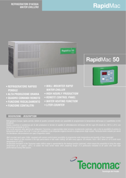
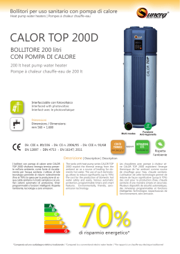
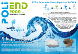
PRO
VISO
VOR
IRE
- SEU
LÄU
FIG
L EN
- NU
ANG
R EN
LAIS
GLIS
ET IT
H UN
D ITA ALIEN
LIEN
ISCH
SERVICE MANUAL - MANUALE DI SERVIZIO
MANUEL DE SERVICE - BEDIENUNGSANLEITUNG
20 - 30
40 - 50
65 - 90
R 134 A
Ice cubers
Fabbricatori
di ghiaccio a cubetti
Machines á glaçons
Eiswürfelbereiter
REV. 02/2001
a)
TABLE OF CONTENTS
PAGE
INDICE
PAG
TABLE DES MATIERES
PAGE
INHALT
SEITE
GENERAL INFORMATION
AND INSTALLATION
1
INFORMAZIONI GENERALI
ED INSTALLAZIONE
11
INFORMATIONS GENERALES
ET INSTALLATION
20
ALLGEMEINES UND
INSTALLATION
Introduction
Unpacking and inspection
Location and levelling
1
1
1
Introduzione
11
Disimballaggio ed ispezione 11
Posizionamento e livellamento 11
Introduction
20
Déballage et examen
20
Logement et mise de niveau 20
Einleitung
27
Auspacken und Kontrollieren 27
Stellplatz und Aufstellung
27
Electrical connection
Water supply and drain
connection
Final check list
Installation practice
1
2
3
3
Collegamenti elettrici
Alimentazione idraulica
e scarico
Controllo finale
Schema di installazione
12
13
13
Branchement électrique
Branchement d’arrivée
et d’évacuation eau
Liste de contrôle final
Schema d’installation
21
22
22
Elektrische Anschlüsse
Wasserversorgung und
Abflußleitungen
Endkontrolle
Installation
28
29
29
OPERATING INSTRUCTION
4
ISTRUZIONI DI
FUNZIONAMENTO
14
MISE EN SERVICE
23
BETRIEBSANLEITUNG
30
Start up
Operational checks
4
4
Avviamento
14
Controlli durante il funzion. 14
Démarrage
23
Contrôle pendant le fonctionn. 23
Inbetriebnahme
Kontrolle bei Betrieb
30
30
OPERATING PRINCIPLES
6
PRINCIPIO DI
FUNZIONAMENTO
16
PRINCIPE DE
FONCTIONNEMENT
24
BETRIEB
31
Freezing cycle
Harvest cycle
6
6
Ciclo di congelamento
Ciclo di scongelamento
16
16
Cycle de congélation
Cycle de démoulage
24
24
Gefrierzyklus
Abtauzyklus
31
31
ANWEISUNGEN ZUR
WARTUNG UND REINIGUNG
33
CLEANING INSTRUCTIONS OF
WATER SYSTEM
9
12
ISTRUZIONI PER LA PULIZIA
DEL CIRCUITO IDRAULICO 19
20
INSTRUCTION DE NETTOYAGE
DU CIRCUIT HYDRAULIQUE
26
27
28
b)
20 - 30 (mm/inc.)
50 (mm./inc.)
40-65-90 (mm/inc.)
A
386 (15 3/16") - 462 (18 3/16")
529 (20 53/64")
690 (27 11/64")
B
500 (19 44/64") - 525 (20 43/64")
535 (21 1/16")
534 (21 1/32")
C
675 (26 1/2") - 715 (28 1/16")
794 (31 17/64")
877 (34 17/32")
c)
d)
TECHNICAL SPECIFICATIONS - SPECIFICHE TECNICHE - DONNÉES TECHNIQUE - TECHNISCHE ANGABEN
20A
20W
30A
30W
40A
40W
50A
50W
65A
65W
90A
90W
Electric voltage
Alimentazione elettrica
Alimentation électrique
Netzspannung
230/50/1
-10 ÷ +10%
230/50/1
-10 ÷ +10%
230/50/1
-10 ÷ +10%
230/50/1
-10 ÷ +10%
230/50/1
-10 ÷ +10%
230/50/1
-10 ÷ +10%
Condensation
Condensazione
Condensation
Kühlung
Air
Aria
Air
Luft
Air
Aria
Air
Luft
Air
Aria
Air
Luft
Air
Aria
Air
Luft
Water
Acqua
Eau
Wasser
Air
Aria
Air
Luft
Air
Aria
Air
Luft
18
18
Bin capacity (kg)
Capacità contenitore (kg)
Capacité bac glaçons (kg)
Lademenge (kg)
32
48
48
3/8
3/8
1/2
3/4
2,4
3,2
3,5
3,8
5,3
9
11
17
18
20
26
340
380
500
550
670
830
7
8
10
10
13
16
3 x 1,5
3 x 1,5
3 x 1,5
3 x 1,5
3 x 1,5
3 x 1,5
Start amps
Amperaggio d’avv.
Ampérage de démarr.
Start Ampere
Power (Watts)
Potenza (Watt)
Puissance (Watts)
Leistung (Watt)
Power cons. in 24 hrs (Kwh)
Consumo elettr. in 24 ore (Kwh)
Cons. electr. en 24 hrs (Kwh)
Stromverbrauch in 24 Std. (kWh)
Refrigerant metering device
Disp. espansione refrigerante
Détente du Rèfrigérant
Kühlmittel - Expansionssystem
13
16
35
39
45
18
24
24
1/5
1/4
2,2
Water
Acqua
Eau
Wasser
73
Running amps
Amperaggio di marcia
Ampérage en marche
Ampere
8
Water
Acqua
Eau
Wasser
61
Compressor power HP
Potenza compressore CV
Puissance compresseur CV
Kompressorleistung PS
Refrig. charge R 134 A (gr)
Carica refrig. R 134 A (gr)
Charge refrig. R 134 A (gr)
Kühlmittel - Füll. R 134 A (gr)
Water
Acqua
Eau
Wasser
30
Cubes per cycle
Cubetti per ciclo
Glaçons par cycle
Würfel per Zyklus
Water consumption (lt/hr)
Consumo acqua (lt/ora)
Consommation eau (lt/hr)
Wasserverbrauch (lt/std)
Water
Acqua
Eau
Wasser
30
Net weight (kg)
Peso netto (kg)
Poids net (kg)
Nettogewicht (kg)
Wire size (mm2)
Sezione cavi (mm2)
Section fils (mm2)
Kabelstärke (mm2)
Water
Acqua
Eau
Wasser
4
11*
4
15*
6
16*
8
30 *
7
34*
11
42*
250
250
260
250
290
250
320
250
450
300
450
330
Capillary tube
Tubo capillare
Tube Capillaire
Kapillarrohr
Capillary tube
Tubo capillare
Tube Capillaire
Kapillarrohr
Capillary tube
Tubo capillare
Tube Capillaire
Kapillarrohr
Capillary tube
Tubo capillare
Tube Capillaire
Kapillarrohr
Capillary tube
Tubo capillare
Tube Capillaire
Kapillarrohr
Capillary tube
Tubo capillare
Tube Capillaire
Kapillarrohr
Water - Acqua - Eau - Wasser: 15°C (60°F)
OPERATING PRESSURES - PRESSIONI DI FUNZIONAMENTO - PRESSIONES DE FONCTIONNEMENT - BETRIEBSDRÜCKE
Discharge pressure - Pressione di mandata
Haute pression - Hochdruckbereich
Suction pressure - Pressione di aspirazione
Basse pression - Niederdrück
Freezing cycle - Ciclo di congelamento
Cycle de Congélation - Gefrierfase
End of freezing cycle - Fine ciclo di congelamento
Fin du cycle de congélation - Ende der Gefrierfase
Air cooled - Raffr. ad aria
Refroid. à air - Luftgekühlt
20-30-40
7÷11 bar
100÷155 psig
0÷0.1 bar
0÷1.5 psig
Air cooled - Raffr. ad aria
Refroid. à air - Luftgekühlt
50-65-90
8.5÷10 bar
120÷140 psig
0.2÷0.3 bar
3÷4 psig
8.5÷10 bar
120÷140 psig
0÷0.1 bar
0÷1.5 psig
9.5 bar
130 psig
0.2÷0.3 bar
3÷4 psig
Water cooled - Raffr. ad acqua
20-30-40-50
Refroid. à eau - Wassergekühlt
Water cooled - Raffr. ad acqua
65-90
Refroid. à eau - Wassergekühlt
d
20 - 30 - 40
e)
WIRING DIAGRAM - SCHEMA ELETTRICO - SCHÉMA ÉLECTRIQUE - SCHALTUNGSSCHEMA
AIR & WATER COOLED - RAFFREDDAMENTO AD ARIA ED AD ACQUA.
REFROIDISSEMENT A AIR ET A EAU - LUFT- UND WASSERGEKÜHLT
230/50-60/1
B - WHITE
BIANCO
BLANC
WEISS
N - BLACK
NERO
NOIR
SCHWARZ
A - BLUE
BLU
BLEU
BLAU
M - BROWN
MARRONE
MARRON
BRAUN
GV - YELLOW GREEN
GIALLO VERDE
JAUNE VERT
GELB - GRÜN
JUST FOR WATER COOLED UNIT
SOLO PER RAFF. AD ACQUA
SEUL POUR REFR. A EAU
NUR FÜR WASSERGEKÜHLTE EINHEIT
1 TERMINAL BOARD - MORSETTIERA
BORNIER - ANSCHLUSSKASTEN
2 EVAPORATOR THERMOSTAT - TERMOSTATO EVAPORATORE
THERMOSTAT EVAPORATEUR - VERDAMPFERTHERMOSTAT
3 BIN THERMOSTAT - TERMOSTATO CONTENITORE
THERMOSTAT CABINE - SPEICHERTHERMOSTAT
4 COMPRESSOR - COMPRESSORE
COMPRESSEUR - KOMPRESSOR
5 WATER PUMP - POMPA
POMPE A EAU - WASSERPUMPE
6 FAN MOTOR - VENTILATORE
MOTOVENTILATEUR - LÜFTERMOTOR
7 WATER SOL. VALVE - VALV. INGR. ACQUA
VANNE ARRIVÉE EAU - WAISSEREINLASSVENTIL
8 HOT. GAS VALVE - VALVOLA GAS CALDO
VANNE GAZ CHAUDS - HEISSGASVENTIL
JUST FOR AIR COOLED UNIT
SOLO PER RAFF. AD ARIA
SEUL POUR REFR. A AIR
NUR FÜR LUFTGEKÜHLTE EINHEIT
9 HI TEMP. THERMOSTAT - TERMOSTATO DI MASSIMA
THERMOSTAT DE SECURITÉ - SICHERHEITSTHERMOSTAT
10 FILLING SWITCH - INTERRUTTORE CARICO
INTERRUPTEUR CHARGEMENT EAU - FÜLLSCHALTER
11 PRESSURE CTRL - PRESSOSTATO
PRESSOSTAT - DRUCKSCHALTER
12 COND. WATER SOL. VALVE - VALV. ALIM. ACQUA COND.
VANNE ARR. EAU CONDEN. - WASSEREINLASSVENTIL KOND.
d
f)
50
WIRING DIAGRAM - SCHEMA ELETTRICO - SCHÉMA ÉLECTRIQUE - SCHALTUNGSSCHEMA
AIR & WATER COOLED - RAFFREDDAMENTO AD ARIA ED AD ACQUA.
REFROIDISSEMENT A AIR ET A EAU - LUFT- UND WASSERGEKÜHLT
230/50-60/1
B - WHITE
BIANCO
BLANC
WEISS
N - BLACK
NERO
NOIR
SCHWARZ
A - BLUE
BLU
BLEU
BLAU
M - BROWN
MARRONE
MARRON
BRAUN
GV - YELLOW GREEN
GIALLO VERDE
JAUNE VERT
GELB - GRÜN
14
13
2
3
12
11
9
1
8
7
4
5
6 10
11
12
3
9
2
14
1
6 10
1 TERMINAL BOARD - MORSETTIERA
BORNIER - ANSCHLUSSKASTEN
2 EVAPORATOR THERMOSTAT - TERMOSTATO EVAPORATORE
THERMOSTAT EVAPORATEUR - VERDAMPFERTHERMOSTAT
3 BIN THERMOSTAT - TERMOSTATO CONTENITORE
THERMOSTAT CABINE - SPEICHERTHERMOSTAT
4 COMPRESSOR - COMPRESSORE
COMPRESSEUR - KOMPRESSOR
5 WATER PUMP - POMPA
POMPE A EAU - WASSERPUMPE
13
7
8
6 FAN MOTOR - VENTILATORE
MOTOVENTILATEUR - LÜFTERMOTOR
7 WATER SOL. VALVE - VALV. INGR. ACQUA
VANNE ARRIVÉE EAU - WAISSEREINLASSVENTIL
8 HOT. GAS VALVE - VALVOLA GAS CALDO
VANNE GAZ CHAUDS - HEISSGASVENTIL
9 PRESSURE CTRL - PRESSOSTATO
PRESSOSTAT - DRUCKSCHALTER
10 COND. WATER SOL. VALVE - VALV. ALIM. ACQUA COND.
VANNE ARR. EAU CONDEN. - WASSEREINLASSVENTIL KOND.
5
4
11 SWITCH - INTERRUTTORE
INTERRUPTEUR - SCHALTER
12 HI THERMOSTAT - TERMOSTATO DI SICUREZZA
THERMOSTAT DE SECURITE - SICHERHEITSTHERMOSTAT
13 TIMER - TIMER
PENDULE - ZEITHUR
14 FILLING SWITCH - INTERRUTTORE CARICO
INTERRUPTEUR CHARGEMENT EAU - FÜLLSCHALTER
d
65 - 90
g)
WIRING DIAGRAM - SCHEMA ELETTRICO - SCHÉMA ÉLECTRIQUE - SCHALTUNGSSCHEMA
AIR & WATER COOLED - RAFFREDDAMENTO AD ARIA ED AD ACQUA.
REFROIDISSEMENT A AIR ET A EAU - LUFT- UND WASSERGEKÜHLT
230/50-60/1
B - WHITE
BIANCO
BLANC
WEISS
N - BLACK
NERO
NOIR
SCHWARZ
A - BLUE
BLU
BLEU
BLAU
M - BROWN
MARRONE
MARRON
BRAUN
GV - YELLOW GREEN
GIALLO VERDE
JAUNE VERT
GELB - GRÜN
10
13
2
3
9
13
12
11
14
1
7
5
8
4
6
12
9
3
11
2
10
14
4
14
1
1 TERMINAL BOARD - MORSETTIERA
BORNIER - ANSCHLUSSKASTEN
2 EVAPORATOR THERMOSTAT - TERMOSTATO EVAPORATORE
THERMOSTAT EVAPORATEUR - VERDAMPFERTHERMOSTAT
3 BIN THERMOSTAT - TERMOSTATO CONTENITORE
THERMOSTAT CABINE - SPEICHERTHERMOSTAT
4 COMPRESSOR - COMPRESSORE
COMPRESSEUR - KOMPRESSOR
5 WATER PUMP - POMPA
POMPE A EAU - WASSERPUMPE
6
13
7
8
5
6 FAN MOTOR - VENTILATORE
MOTOVENTILATEUR - LÜFTERMOTOR
7 WATER SOL. VALVE - VALV. INGR. ACQUA
VANNE ARRIVÉE EAU - WAISSEREINLASSVENTIL
8 HOT. GAS VALVE - VALVOLA GAS CALDO
VANNE GAZ CHAUDS - HEISSGASVENTIL
9 HI TEMP. THERMOSTAT - TERMOSTATO DI MASSIMA
THERMOSTAT DE SECURITÉ - SICHERHEITSTHERMOSTAT
10 FILLING SWITCH - INTERRUTTORE CARICO
INTERRUPTEUR CHARGEMENT EAU - FÜLLSCHALTER
11 PRESSURE CTRL - PRESSOSTATO
PRESSOSTAT - DRUCKSCHALTER
12 SWITCH - INTERRUTTORE
INTERRUPTEUR - SCHALTER
13 TIMER - TIMER
PENDULE - ZEITHUR
14 CONTACTOR - TELERUTTORE
CONTACTEUR - SCHALTSCHUTZ
h)
e
17
32
16
38
15
14
13
27
21
15
20
TEMPERATURA ACQUA - WATER TEMPERATURE
TEMPÉRATURE DE L'EAU - WASSERTEMPERATUR
°C
10
Kg.
29
28
21
27
26
25
24
32
23
22
38
21
20
19
18
27
21
15
10
TEMPERATURA AMBIENTE - AMBIENT TEMPERATURE
TEMPÉRATURE AMBIANT - RAUMTEMPERATUR
RAFFREDDAMENTO AD ARIA - AIR COOLED MODELS
CONDENSATION PAR AIR - LUFTKÜHLUNG
30
TEMPERATURA ACQUA - WATER TEMPERATURE
TEMPÉRATURE DE L'EAU - WASSERTEMPERATUR
RAFFREDDAMENTO AD ARIA - AIR COOLED MODELS
CONDENSATION PAR AIR - LUFTKÜHLUNG
°C
Kg.
42
40
10
21
38
36
34
32
32
38
30
28
26
24
22
32
27
15
TEMPERATURA ACQUA - WATER TEMPERATURE
TEMPÉRATURE DE L'EAU - WASSERTEMPERATUR
40
22
21
21
20
32
19
38
18
17
16
15
14
13
21
15
TEMPERATURA AMBIENTE - AMBIENT TEMPERATURE
TEMPÉRATURE AMBIANT - RAUMTEMPERATUR
18
°C
10
Kg.
23
TEMPERATURA ACQUA - WATER TEMPERATURE
TEMPÉRATURE DE L'EAU - WASSERTEMPERATUR
RAFFREDDAMENTO AD ACQUA - WATER COOLED MODELS
CONDENSATION PAR EAU - WASSERKÜHLUNG
Kg.
29
°C
28
10
27
21
26
32
25
38
24
23
22
21
20
19
18
32
21
15
10
TEMPERATURA AMBIENTE - AMBIENT TEMPERATURE
TEMPÉRATURE AMBIANT - RAUMTEMPERATUR
19
RAFFREDDAMENTO AD ACQUA - WATER COOLED MODELS
CONDENSATION PAR EAU - WASSERKÜHLUNG
TEMPERATURA ACQUA - WATER TEMPERATURE
TEMPÉRATURE DE L'EAU - WASSERTEMPERATUR
RAFFREDDAMENTO AD ACQUA - WATER COOLED MODELS
CONDENSATION PAR EAU - WASSERKÜHLUNG
°C
Kg.
42
40
38
10
36
21
34
32
32
38
30
28
26
24
22
32
15
10
TEMPERATURA ACQUA - WATER TEMPERATURE
TEMPÉRATURE DE L'EAU - WASSERTEMPERATUR
TEMPERATURA AMBIENTE - AMBIENT TEMPERATURE
TEMPÉRATURE AMBIANT - RAUMTEMPERATUR
21
20
PRODUZIONE GHIACCIO PER 24 ORE - ICE PRODUCED PER 24 HRS.
PRODUCTION DE GLACE PAR 24 HEURES - EISWÜRFELPRODUKTION IN 24 STD.
21
PRODUZIONE GHIACCIO PER 24 ORE - ICE PRODUCED PER 24 HRS.
PRODUCTION DE GLACE PAR 24 HEURES - EISWÜRFELPRODUKTION IN 24 STD.
22
PRODUZIONE GHIACCIO PER 24 ORE - ICE PRODUCED PER 24 HRS.
PRODUCTION DE GLACE PAR 24 HEURES - EISWÜRFELPRODUKTION IN 24 STD.
°C
10
Kg.
23
TEMPERATURA AMBIENTE - AMBIENT TEMPERATURE
TEMPÉRATURE AMBIANT - RAUMTEMPERATUR
RAFFREDDAMENTO AD ARIA - AIR COOLED MODELS
CONDENSATION PAR AIR - LUFTKÜHLUNG
TEMPERATURA AMBIENTE - AMBIENT TEMPERATURE
TEMPÉRATURE AMBIANT - RAUMTEMPERATUR
PRODUZIONE GHIACCIO PER 24 ORE - ICE PRODUCED PER 24 HRS.
PRODUCTION DE GLACE PAR 24 HEURES - EISWÜRFELPRODUKTION IN 24 STD.
PRODUZIONE GHIACCIO PER 24 ORE - ICE PRODUCED PER 24 HRS.
PRODUCTION DE GLACE PAR 24 HEURES - EISWÜRFELPRODUKTION IN 24 STD.
PRODUZIONE GHIACCIO PER 24 ORE - ICE PRODUCED PER 24 HRS.
PRODUCTION DE GLACE PAR 24 HEURES - EISWÜRFELPRODUKTION IN 24 STD.
Capacità di produzione - Ice making capacity - Capacité de production - Eisproduktionskapazität
i)
32
40
38
38
36
34
32
30
32
27
21
15
10
50
TEMPERATURA ACQUA - WATER TEMPERATURE
TEMPÉRATURE DE L'EAU - WASSERTEMPERATUR
Kg.
75
°C
70
10
21
65
32
60
38
55
50
45
40
32
27
21
15
10
TEMPERATURA AMBIENTE - AMBIENT TEMPERATURE
TEMPÉRATURE AMBIANT - RAUMTEMPERATUR
RAFFREDDAMENTO AD ARIA - AIR COOLED MODELS
CONDENSATION PAR AIR - LUFTKÜHLUNG
65
TEMPERATURA ACQUA - WATER TEMPERATURE
TEMPÉRATURE DE L'EAU - WASSERTEMPERATUR
RAFFREDDAMENTO AD ARIA - AIR COOLED MODELS
CONDENSATION PAR AIR - LUFTKÜHLUNG
°C
10
Kg.
85
21
80
32
75
70
38
65
60
55
50
32
27
21
15
10
TEMPERATURA ACQUA - WATER TEMPERATURE
TEMPÉRATURE DE L'EAU - WASSERTEMPERATUR
90
°C
10
48
21
46
44
32
42
38
40
38
36
34
32
30
32
27
21
15
10
TEMPERATURA AMBIENTE - AMBIENT TEMPERATURE
TEMPÉRATURE AMBIANT - RAUMTEMPERATUR
42
Kg.
50
TEMPERATURA ACQUA - WATER TEMPERATURE
TEMPÉRATURE DE L'EAU - WASSERTEMPERATUR
RAFFREDDAMENTO AD ACQUA - WATER COOLED MODELS
CONDENSATION PAR EAU - WASSERKÜHLUNG
Kg.
75
°C
70
10
21
65
32
60
38
55
50
45
40
32
27
21
15
10
TEMPERATURA AMBIENTE - AMBIENT TEMPERATURE
TEMPÉRATURE AMBIANT - RAUMTEMPERATUR
44
RAFFREDDAMENTO AD ACQUA - WATER COOLED MODELS
CONDENSATION PAR EAU - WASSERKÜHLUNG
TEMPERATURA ACQUA - WATER TEMPERATURE
TEMPÉRATURE DE L'EAU - WASSERTEMPERATUR
RAFFREDDAMENTO AD ACQUA - WATER COOLED MODELS
CONDENSATION PAR EAU - WASSERKÜHLUNG
°C
10
Kg.
85
21
80
32
75
38
70
65
60
55
50
32
27
21
15
10
TEMPERATURA ACQUA - WATER TEMPERATURE
TEMPÉRATURE DE L'EAU - WASSERTEMPERATUR
TEMPERATURA AMBIENTE - AMBIENT TEMPERATURE
TEMPÉRATURE AMBIANT - RAUMTEMPERATUR
21
46
PRODUZIONE GHIACCIO PER 24 ORE - ICE PRODUCED PER 24 HRS.
PRODUCTION DE GLACE PAR 24 HEURES - EISWÜRFELPRODUKTION IN 24 STD.
48
PRODUZIONE GHIACCIO PER 24 ORE - ICE PRODUCED PER 24 HRS.
PRODUCTION DE GLACE PAR 24 HEURES - EISWÜRFELPRODUKTION IN 24 STD.
°C
10
PRODUZIONE GHIACCIO PER 24 ORE - ICE PRODUCED PER 24 HRS.
PRODUCTION DE GLACE PAR 24 HEURES - EISWÜRFELPRODUKTION IN 24 STD.
Kg.
50
TEMPERATURA AMBIENTE - AMBIENT TEMPERATURE
TEMPÉRATURE AMBIANT - RAUMTEMPERATUR
RAFFREDDAMENTO AD ARIA - AIR COOLED MODELS
CONDENSATION PAR AIR - LUFTKÜHLUNG
TEMPERATURA AMBIENTE - AMBIENT TEMPERATURE
TEMPÉRATURE AMBIANT - RAUMTEMPERATUR
PRODUZIONE GHIACCIO PER 24 ORE - ICE PRODUCED PER 24 HRS.
PRODUCTION DE GLACE PAR 24 HEURES - EISWÜRFELPRODUKTION IN 24 STD.
PRODUZIONE GHIACCIO PER 24 ORE - ICE PRODUCED PER 24 HRS.
PRODUCTION DE GLACE PAR 24 HEURES - EISWÜRFELPRODUKTION IN 24 STD.
PRODUZIONE GHIACCIO PER 24 ORE - ICE PRODUCED PER 24 HRS.
PRODUCTION DE GLACE PAR 24 HEURES - EISWÜRFELPRODUKTION IN 24 STD.
Capacità di produzione - Ice making capacity - Capacité de production - Eisproduktionskapazität
Page 1
GENERAL INFORMATION
AND INSTALLATION
A.
8. Remove the manufacturer’s registration
card from the inside of the User Manual and fillin all parts including: Model and Serial Number
taken from the data plate.
Forward the completed self-addressed
registration card to the factory.
INTRODUCTION
These Cubers are quality designed, engineered
and manufactured.
Their ice making systems are thoroughly tested
providing the utmost in flexibility to fit the needs
of a particular user.
These ice makers have been engineered to our
own rigid safety and performence standards.
NOTE. To retain the safety and performance
built into this icemaker, it is important that
installation and maintenance be conducted
in the manner outlined in this manual.
C.
LOCATION AND LEVELLING
WARNING. This Ice Cuber is designed for
indoor installation only. Extended periods
of operation at temperatures exceeding
the following limitations will constitute
misuse under the terms of the
Manufacturer’s Limited Warranty resulting
in LOSS of warranty coverage.
1. Position the unit in the selected permanent
location.
Criteria for selection of location include:
a) Minimum room temperature 10°C (50°F)
and maximum room temperature 40°C (100°F).
B.
UNPACKING AND INSPECTION
1. Visually inspect the exterior of the packing
and skid. Any severe damage noted should be
reported to the delivering carrier and a concealed
damage claim form filled in subjet to inspection of
the contents with the carrier’s representative
present.
2. a) Cut and remove the plastic strip securing
the carton box to the skid.
b) Cut open the top of the carton and
remove the polystyre protection sheet.
c) Pull out the polystyre posts from the
corners and then remove the carton.
b) Water inlet temperatures: minimum 5°C
(40°F) and maximum 35°C (90°F).
c) Well ventilated location for air cooled
models. Clean the air cooled condenser at
frequent intervals.
d) Service access: adequate space must be
left for all service connections through the rear of
the ice maker. A minimum clearance of 15 cm
(6") must be left at the sides of the unit for routing
cooling air drawn into and exhausted out of the
compartment to maintain proper condensing
operation of air cooled models.
3. Remove the front and the rear panels of the
unit and inspect for any concealed damage.
Notify carrier of your claim for the concealed
damage as stated in step 1 above.
NOTE. With the unit in “built-in” conditions,
the ice production is gradually reduced in
respect to the levels shown in the graph, up
to a maximum of 10% at room temperatures
higher than 32°C.
4. Remove all internal support packing and
masking tape.
The daily ice-making capacity is directly
related to the condenser air inlet temperature, water temperature and age of the machine.
5. Check that refrigerant lines do not rub
against or touch other lines or surfaces, and that
the fan blade moves freely.
To keep your CUBER at peak performance
levels, periodic maintenance checks must
be carried out as indicated on Cleaning
Section of this manual.
6. Use clean damp cloth to wipe the surfaces
inside the storage bin and the outside of the
cabinet.
2. Level the unit in both the left to right and
front to rear directions.
7. See data plate on the rear side of the unit
and check that local main voltage corresponds
with the voltage specified on it.
CAUTION. Incorrect voltage supplied to
the icemaker will void your parts
replacement program.
D.
ELECTRICAL CONNECTIONS
See data plate for current requirements to
determine wire size to be used on electrical
connections. All icemakers require a solid earth
wire.
Page 2
The ice machines are supplied from the factory
completely pre-wired and require only electrical
power connections to wire cord provided on the
back of the unit.
Make sure that the ice machine is connected to
its own circuit and individually fused (see data
plate for fuse size).
The maximum allowable voltage variation should
not exceed -10% and +10% of the data plate
rating. Low voltage can cause faulty functioning
and may be responsible for serious damage to
the overload switch and motor windings.
NOTE. All external wiring should conform to
national, state and local standards and
regulations.
Check voltage on the line and the ice maker’s
data plate before connecting the unit.
E.
WATER SUPPLY AND DRAIN
CONNECTIONS
General
When choosing the water supply for the ice cuber
consideration should be given to:
Water supply - Water cooled models
(65-90)
The water cooled versions of series 65 and 90
require two separate inlet water supplies, one for
the water sprayed for making the ice cubes and
the other for the water cooled condenser.
Connect the 3/4" male fitting of the water
regulating valve using the flexible hose supplied
with the unit to the cold water supply line with
regular plumbing fitting and a shut-off valve
installed in an accessible position between the
water supply line and the unit.
Water drain
The recommended drain tube is a plastic or
flexible tube with 18 mm (3/4") I.D. runs to an
open trapped and vented drain. When the drain
is a long run, allow 3 cm pitch per meter (1/4"
pitch per foot).
A vertical open vent, at the unit drain connection,
is also required for proper sump drainage.
a) Length of run
b) Water clarity and purity
Water drain - Water cooled models
c) Adequate water supply pressure
The water drain line from the condenser, on
water cooled versions, is internally connected
with the drain fitting of the unit.
It is strongly recommended therefore to install a
vertical open vent on unit drain line high point to
ensure good draining and to direct the drain line
to a trapped and vented floor drain receptacle.
This to make sure of the proper flow of the
drained water as, in case of poor drainage, the
water ranning out from the condenser may
inopportunely flow, through the unit drain tubing,
into the ice storage bin or into the sump reservoir.
Since water is the most important single ingredient
in producting ice you cannot emphasize too
much the three items listed above.
Low water pressure, below 1 bar may cause
malfunction of the ice maker unit.
Water containing excessive minerals will tend to
produce cloudy coloured ice cubes, plus scale
built-up on parts of the water system.
Water supply
Connect the 3/4" male fitting of the solenoid
water inlet valve, using the flexible tubing supplied,
to the cold water supply line with regular plumbing
fitting and a shut-off valve installed in an
accessible position between the water supply
line and the unit.
NOTE. The water supply and the water drain
must be installed to conform with the local
code. In some case a licensed plumber and/
or a plumbing permit is required.
Page 3
F.
FINAL CHECK LIST
1 bar (14 psi).
1. Is the unit in a room where ambient
temperatures are within a minimum of 10°C
(50°F) even in winter months?
2. Is there at least a 15 cm (6") clearance
around the unit for proper air circulation?
3.
8. Have the bin liner and cabinet been wiped
clean?
9. Has the owner/user been given the User
Manual and been instructed on the importance of
periodic maintenance checks?
Is the unit level? (IMPORTANT)
4. Have all the electrical and plumbing
connections been made, and is the water supply
shut-off valve open?
5. Has the voltage been tested and checked
against the data plate rating?
6. Has the water supply pressure been
checked to ensure a water pressure of at least
G.
7. Check all refrigerant lines and conduit lines
to guard against vibrations and possible failure.
10. Has the Manufacturer’s registration card
been filled in properly? Check for correct model
and serial number against the serial plate and
mail the registration card to the factory.
11. Has the owner been given the name and
the phone number of the authorized Service
Agency serving him?
INSTALLATION PRACTICE
1.
2.
3.
4.
5.
6.
7.
8.
9.
Hand shut-off valve
Water filter
Water supply line (flexible hose)
3/4" male fitting
Vented drain
Open trapped vented drain
Drain fitting
Main switch
Power line
WARNING. This icemaker is not designed for outdoor installation and will not function in
ambient temperatures below 10°C (50°F) or above 40°C (100°F).
This icemaker will malfunction with water temperatures below 5°C (40°F) or above 35°C
(90°F).
Page 4
OPERATING INSTRUCTIONS
START UP
position. This will close the electrical circuit to the
water inlet valve and to the hot gas valve.
After having correctly installed the ice maker and
completed the plumbing and electrical
connections, perform the following “Start-up” procedure.
E.
Switch ON the power line disconnect
switch. Unit will start up in defrost cycle mode.
20-30-40
A.
Remove the unit front panel and locate the
cleaning switch on the control box.
During this cycle the components energized are:
WATER INLET SOLENOID VALVE
HOT GAS SOLENOID VALVE
TIMER MOTOR
B.
Set the cleaning switch in the cleaning
position. This will close the electrical circuit to the
water inlet valve and to the hot gas valve
C.
Switch ON the power line disconnect
switch. Unit will start up in defrost cycle mode.
During this cycle the components energized are:
WATER INLET SOLENOID VALVE
HOT GAS SOLENOID VALVE
The Water pump and the Fan motor are also in
operation.
F.
After completion of harvest cycle (about
three minutes) move the compressor switch to
ON position.
NOTE. During the defrost cycle, the water
inlet solenoid valve is energized. The water
flows through the valve to the back side of the
evaporator platen and then down to fill up the
icemaker sump tank for the next freezing
cycle.
OPERATIONAL CHECKS
D.
Let unit stay in defrost cycle for about
three/four minutes till water is coming out from
the drain hose, then move the cleaning switch to
the operation position.
50-65-90
A.
Remove the unit front panel and locate the
timer shaft on the control box.
B.
Check that master and the compressor
switch located on the lower left hand side of the
control box are both in the OFF position.
C.
Rotate the timer shaft protruding through
the front of the control box clockwise, until and
audible click is heard indicating that the actuator
arm of the microswitch has dropped into the cam
slot (Fig. A).
E.
The unit now starts its first freezing cycle
with the following components in operation:
COMPRESSOR
WATER PUMP
FAN MOTOR in air cooled version
F.
Check to see through the ice discharge
opening that the spray system is correctly seated
and that the water jets uniformely reach the
interior of the inverted cup molds; also make sure
that the plastic curtain is hanging freely and there
is not excessive water spilling through it.
G.
The ice making process takes place
thereby, with the water sprayed into the molds
that gets gradually refrigerated by the heat
exchanged with the refrigerant flowing into the
evaporator serpentine.
H.
On units 20-30-40 when the evaporator
temperature reaches a preset value the
evaporator thermostat or cube size control
changes its contacts; the freezing cycle ends and
starts the defrost or harvest cycle.
D.
Set the master switch to the ON position.
The compressor switch must stay in the OFF
I.
On units 50-65-90 the time clock does not
rotate at the end of the harvest cycle. It starts
later when the cube size thermostat control bulb
(pig tail) located on the evaporator coil reaches a
temperature of approx. -15°C (5°F).
Page 5
Freezing time will range between 20 and 22
minutes in a 21°C ambient temperature, longer if
above this temperature and shorter if below. The
average complete cycle time is between 23 and
25 minutes.
If the ice cubes are shallow and cloudy, it is
possible that the ice maker runs short of water
during the end of the freezing cycle or, the quality
of the supplied water requires the use of an
appropriate water filter or conditioner.
K.
Check, during the first defrost/harvest
cycle, that the incoming water flows correctly into
the sump reservoir in order to re-fill it and the
surplus overflows through the overflow drain
tube.
N.
At the end of the defrost or harvest cycle
hold a handful of ice cubes against the bulb of the
storage bin thermostat; the icemaker switch OFF
in about one-two minutes.
Take out the ice from the storage bin thermostat.
The ice maker should restart automatically in
three-four minutes.
L.
Check the texture of ice cubes just
released. Right size must have a small depression
(about 5-6 mm) in their crown.
If not, wait for the second defrost/harvest cycle
before performing any adjustment.
M.
If required, the length of the freezing cycle
can be modified by turning the knob of the cube
size control or evaporator thermostat located in
front of the control box until the desired size is
achieved.
NOTE. The bin thermostat is factory set at
1°C (35°F) OUT and 4°C (39°F) IN.
O.
Re-fit the unit front panel then instruct the
owner/user on the general operation of the ice
machine and about the cleaning and care it
requires.
Page 6
PRINCIPLE OF OPERATION
How it works
In the ice makers the water used to make the ice
is kept constantly in circulation by a water pump
which primes it to the spray system nozzles from
where it is diverted into the inverted cup molds of
the evaporator (Fig. A).
A small quantity of the sprayed water freezes into
ice; the rest of it cascades by gravity into the
sump assembly below for recirculation.
FREEZING CYCLE (Fig. B)
The hot gas refrigerant discharged out from the
compressor reaches the condenser where, being
cooled down, condenses into liquid. Flowing into
the liquid line it passes through the drier/filter,
then it goes all the way through the capillary tube
where it looses its pressure.
Next the refrigerant enters into the evaporator
serpentine (which has a larger diameter then the
capillary tube) and starts to boil off; this reaction
is emphasized by the heat transferred by the
sprayed water.
The refrigerant then increases in volume and
changes entirely into vapor.
The vapor refrigerant then passes through the
suction accumulator (used to prevent that any
small amount of liquid refrigerant may reach the
compressor) and through the suction line. In both
the accumulator and the suction line it exchanges
heat with the refrigerant flowing into the capillary
tube (warmer), before to be sucked in the
compressor and to be recirculated as hot
compressed refrigerant gas.
The freezing cycle on 20-30 is controlled by only
the evaporator thermostat which has its bulb in
contact with the evaporator serpentine while in
40-65-90 there is an second phase controlled by
a timer.
The electrical components in operation during
the freezing cycle are:
COMPRESSOR
WATER PUMP
FAN MOTOR (in air cooled version)
On 20-30-40 air cooled versions the refrigerant
head pressure is gradually reduced from a value
of approx. 11 bars (155 psig) at the beginning of
the freezing cycle with the unit at 21°C (70°F)
ambient temperature, to a minimun value of
approx. 7 bars (100 psig) just at the end of the
freezing cycle few seconds before the starting of
the defrost cycle.
On 50-65-90 air cooled versions the refrigerant
head pressure is kept between two pre-set values
(10÷8,5 bar - 140÷120 psig) with the unit a 21°C
(70°F) ambient temperature.
The declining of the pressure is relied to the
reduction of the evaporating pressure, caused
by the progressive growth of the ice thickness
into the inverted cup molds and to the flow of air
drown through the air cooled condenser by the
fan motor.
The above values are in relation as well to the
ambient temperature of the ice maker site and
they are subject to rise with the increase of this
temperature.
On 20-30-40 water cooled versions the refrigerant
head pressure ranges between 8.5 and 10 bars
(120÷140 psig) being controlled by an automatic
hi pressure control that energizes a water solenoid
valve located on the water line to the condenser,
which rates the cooling water to the condenser.
On 65-90 water cooled versions the head
pressure is constant at 9.5 bar (135 psig)
controlled by a water regulating valve.
At starting of freezing cycle the refrigerant suction
or lo-pressure lowers rapidly to 1.0 bar - 14 psig
then it declines gradually - in relation with the
growing of the ice thickness - to reach, at the end
of the cycle, approx. 0÷0.1 bar - 0÷1.5 psig on
the models 20, 30 and 40 and 0.2÷0.3 bar (3÷4
psig) on models 50, 65 and 90 with the cubes fully
formed in the cup molds.
The total length of the freezing cycle ranges from
23 to 25 minutes.
DEFROST OR HARVEST CYCLE (Fig. D)
On 20-30-40 the temperature of the evaporator
thermostat, in contact with the evaporator
serpentine, drops to a pre-set value it changes its
electrical contacts energizing the herebelow
shown components.
(On 50-65-90 when the timer microswitch drops
down into the lower portion of the cam it changes
its electrical contacts energizing same components).
COMPRESSOR
WATER INLET SOLENOID VALVE
HOT GAS SOLENOID VALVE
The incoming water, passing through the water
inlet valve and the flow control, runs over the
evaporator platen and then flows by gravity
through the dribbler holes down into the sump/
reservoir (Fig. C).
The water filling the sump/reservoir forces part of
the surplus water from the previous freezing
cycle to go out to the waste through the overflow
pipe. This overflow limits the level of the sump
water which will be used to produce the next
batch of ice cubes.
Meanwhile the refrigerant, as hot gas discharged
from the compressor, flows through the hot gas
valve directly into the evaporator serpentine bypassing the condenser.
The hot gas circulating into the serpentine of the
evaporator warms up the copper molds causing
the harvest of the ice cubes. The ice cubes,
released from the cups, drop by gravity onto a
slanted cube chute, then through a curtained
opening they fall into the storage bin.
Page 7
On 20-30-40 when the temperature of the
evaporator thermostat bulb reaches the value of
+3÷4°C their electrical contacts move back to the
previous position activating a new freezing cycle
and deenergizing both the hot gas and the water
inlet valves (closed).
On 50-65-90 as soon as the timer microswitch
completes the bottom part of the cam and it is
pushed again, it activates a new freezing cycle
deenergizing both the hot gas and the water inlet
valves (closed).
NOTE. The length of the defrost/harvest
cycle (not adjustable on 20-30-40) changes
according to the ambient temperature
(shorter for hi ambient temperature and
longer for low one).
COMPONENTS DESCRIPTION
A. WATER PUMP
The water pump operates continually throughout
the freezing cycle. The pump primes the water
from the sump to the spray system and through
the spray nozzles sprays it into the inverted cup
molds to be frozen into crystal clear ice cubes.
It is recommended that the pump motor bearings
be checked at least every six months.
B.
WATER INLET SOLENOID VALVE 3/4 MALE FITTING
The water inlet solenoid valve is energized only
during the defrost cycle.
When energized it allows a metered amount of
incoming water to flow over the evaporator cavity
to assist the hot gas in defrosting the ice cubes.
The water running over the evaporator cavity
drops by gravity, through the dribbler holes of the
platen, into the sump reservoir.
On 20-30-40-50 water cooled versions the water
inlet solenoid valve has one inlet and two outlets
with two separate solenoids energized the first
(ice productioon) by the contacts 3-2 of the
evaporator thermostat and the second (water
cooled condenser) by a specific hi pressure
control.
C. HOT GAS SOLENOID VALVE
The hot gas solenoid valve consists basically in
two parts: the valve body and the valve coil.
During the defrost cycle the hot gas valve coil is
activated so to attract the hot gas valve piston in
order to give way to the hot gas discharged from
compressor to flow directly into the evaporator
serpentine to defrost the formed ice cubes.
D. BIN THERMOSTAT
The bin thermostat control body is located in the
front of control box behind the front panel.
The thermostat sensing tube is located into a
bulb holder on the side wall of the ice storage bin
where it automatically shuts the icemaker OFF
when in contact with the ice and re-starts the
icemaker when the ice is removed. Factory
settings are 1°C (35°F) OUT and 4°C (39°F) IN.
E.
CUBE SIZE CONTROL (EVAPORATOR
THERMOSTAT)
20-30-40
The cube size control (evaporator thermostat)
body is located in the control box behind the front
panel; it’s basically a reverse
acting temperature control which closes the
contacts 3-2 when its temperature decreases
and closes the opposite contacts 3-4 when the
temperature rises.
The thermostat sensing bulb is located into a
plastic tube (bulb holder) secured by two clips
directly to the evaporator serpentine.
This control determines the length of the freezing
cycle and correspondingly the size of the cubes.
A lower setting will produce a larger cube
(oversize) while a higher setting a smaller cuber
(shallow size).
When closed on contacts 3-2 it activates the
defrost or harvest cycle components.
The cube size control is set up in the factory
(knob in the black dot position) and doesn't
require any adjustment when the ambient
temperature remains between 10 and 32°C
(50 and 90°F).
50-65-90
The evaporator thermostat with its sensing bulb
intimately in contact with the regrigerant outlet
tube from the evaporator senses the evaporating
refrigerant temperature (which declines in the
course of the freezing cycle) and when this one
reaches the pre-set value, it switches its contacts
from 3-4 to 3-2 to activate the finishing cycle (2nd
phase) which has a pre-set extension determined
by the large diameter lobe of the timer cam.
F. FAN MOTOR (Air cooled version)
The fan motor on 20-30-40 is electrically
connected in parallel to the water pump and it
operates continuously only during the freezing
cycle keeping the proper head pressure by
circulating air through the condenser fins.
On 50-65-95 the operation of fan motor is
controlled by a fan pressure control adjusted at
preset values.
G. COMPRESSOR
The hermetic compressor is the heart of the
refrigerant system and it is used to circulate and
retrieve the refrigerant throughout the entire
system. It compresses the low pressure
refrigerant vapor causing its temperature to rise
and become high pressure hot vapor (hot gas)
which is then released through the discharge
valve.
H. WATER SPRAY SYSTEM
Through its nozzles it sprays the water in each
individual cup to be frozen into ice.
I.
SAFETY HI TEMPERATURE THERMOSTAT
Located in the control box it is a manual reset
switch that trips OFF the operation of the machine
when its bulb (located on the liquid line just
before the drier) reaches the temperature of
70°C (158°F).
Page 8
J. CLEANING SWITCH (only 20-30-40)
Located on the bottom left side of the control box
is used to energize the water inlet and the hot gas
valves so to charge the water into the sump tank
of the machine.
K.
HI PRESSURE CONTROL (Water cooled
version)
Used only on 20-30-40-50 the water cooled
versions it operates to keep between 8.5 and 10
bars (120 ÷ 140 psig) the hi-side or discharge
pressure of the refrigerant system by energizing
the coil of the water inlet solenoid valve that
control the cooling water flow to the condenser.
L.
TIMER (only 50-65-90)
Equipped with two microswitches which plungers
ride one timer cam, the timer is located inside the
control box.
The function of the timer begins when activated
by the cube size control (evap. thermostat).
The large diameter lobe of its cam determines
the length of the 2nd portion of the freezing cycle,
while the cam small diameter lobe, determines
the time cycle for the harvest sequence.
The timer cam can be adjusted to vary the defrost
time as required.
WARNING. Never set the defrost time for
longer than 4 minutes as this will
jeopardize the compressor motor
windings.
It goes without saying that an extension of the
defrost period will directly reduce the timed portion
of the freezing cycle and viceversa.
Consequently any variation made at the timer
cam setting requires a compensation adjustment,
very fine and very accurate, of the evaporator
thermostat.
M.
MASTER SWITCH (only 50-65-90)
Fitted in the control box the master switch has to
be used to start-up and to stop the ice maker
operation.
N.
COMPRESSOR SWITCH (only 50-65-90)
Located in the control box is used to de-energized
the compressor during the cleaning.
O.
FAN PRESSURE CONTROL
(only 50-65-90)
Used on air cooled ice makers to maintain the
head pressure within the preset values.
P.
WATER REGULATING VALVE
(only 65-90 Water cooled version only)
This valve controls the head pressure in the
refrigerant system by regulating the flow of water
going to the condenser.
As pressure increases, the water regulating valve opens to increase the flow of cooling water.
Q.
CONTACTOR (65-90 only)
It operates in order to close or open the electrical
circuit to the compressor.
Page 9
MAINTENANCE AND CLEANING INSTRUCTIONS
CLEANING INSTRUCTIONS OF WATER
SYSTEM
If necessary remove the water spray platen to
clean it separately.
1. Remove the front and top panels to gain
access either to the control box and to the
evaporator.
2. Make sure that all ice cubes have been
released from their cups, then rotate the cube
size control knob - located on the front control
box - counterclockwise to switch off the unit.
3. Prepare the cleaning solution by diluting in
a plastic container one or two liters of warm water
(45°-50°C) with a 0,1-0,2 liters of Ice Machine
Cleaner (on 20-30-40) and 0,2-0,3 liters on
50-65-90.
WARNING. The Ice Machine Cleaner
contains Phosphoric and Hydroxyacetic
acids.
These compounds are corrosive and may
cause burns if swallowed, DO NOT induce vomiting. Give large amounts of water
or milk. Call Physician immediately.
In case of external contact flush with
water. KEEP OUT OF THE REACH OF
CHILDREN.
4. Scoop out all the ice cubes stored into the
bin in order to prevent them from being
contaminated with the cleaning solution then
flush out the water from the sump reservoir by
removing the overflow stand-pipe.
5. Remove the evaporator cover then slowly
pour onto the evaporator platen the cleaning
solution. With the help of a brush dissolve the
most resistant and remote scale deposits in the
platen.
20-30-40
6. On 20-30-40 rotate the cube size control
knob clockwise to the normal operating position
(black dot) to start the icemaking process.
Allow the ice maker to operate for about 20
minutes. Then turn the cleaning toggle switch to
the "cleaning" position till the release of the ice
cubes from their cups.
b
Turn again the cube size control knob to the
normal operating position (black dot). The water
pump is again in operation to circulate the water
in order to rinse the entire water system.
Do the operation as per steps 8 and 9 twice so to
be sure no more traces of descaling solution
remains into the sump.
Pour on the upper side of the evaporator platen
fresh water with a capfull of disinfectant solution
then turn again the machine in normal operating
mode so to sanitize all the water system for
approx. 10 minutes.
NOTE. Do not mix descaling with disinfectant
solution to avoid the generation of a very
aggressive acid.
Flush out the disinfectant solution from the sump
reservoir then with the switch in "cleaning"
position, turn the cube size control knob to the
normal operating position.
When water starts overflowing through the
drain line, set the switch to "operation" position.
The unit is now ready to resume normal
operation.
50-65-90
7. On 50-65-90 slowly rotate the clock knob
clockwise with the aid of a screwdriver until the
microswitch actuator arm is at the start position
of the freezing cycle.
NOTE. The amount Cleaner and the time
needed for the cleaning of water system
depends of the water conditions.
Turn the cube size control knob counterclockwise
to the OFF position to shut-off the ice maker then
flush out the cleaning solution from the sump
reservoir then pour onto the evaporator cavity
two or three liters of clean potable water to rinse
the mold cups and the platen.
Immediately set the master switch to the ON
position. Leave the compressor switch in the
OFF position.
Page 10
Allow the system to operate for about 20 minutes
into the freezing cycle. No ice will be produced
because the compressor is not in operation.
At the end of this period set the master switch to
the OFF position to shut off the icemaker. Remove
the overflow drain tube from its seat to drain out
all the cleaning solution and most of the mineral
concentration through the drain tube and then
replace it in its seat. Pour onto the evaporator
cavity two or three liters of clean potable water to
rinse the mold cups and the platen.
If necessary remove the water spray platen to
clean it separately (fig. b).
Set again the master switch in ON position. The
water pump is again in operation to circulate
the water in order to rinse the entire water
system.
Pour on the upper side of the evaporator platen
fresh water with a capfull of disinfectant solution
then put again the master switch in ON position
so to sanitize all the water system for approx.
10 minutes.
NOTE. Do not mix descaling with
disinfectant solution to avoid the generation
of a very aggressive acid.
Flush out the disinfectant solution from the
sump reservoir.
Slowly rotate the time clock knob clockwise
until the microswitch actuator arm is in the
START position of the harvest cycle and then
set the master switch to the ON position. Let
the unit run normally through this part of the
cycle. When the defrost has been completed
rotate the time clock knob manually until the
defrost cycle starts again. Do this two times.
Once the water reservoir is properly filled up,
set the compressor switch to the ON position.
The unit is now ready to resume the normal
operation.
Place again the evaporator cover and the unit
service panels.
8. Place again the evaporator cover and the
unit service panels.
9. At completion of the freezing and harvest
cycle make sure of proper texture and clearness
of the ice cubes and that, they do not have any
acid taste.
ATTENTION. In case the ice cubes are
cloudy-white and have an acid taste, melt
them immediately by pouring on them
some warm water. This to prevent that
somebody could use them.
10. Wipe clean and rinse the inner surfaces of
the storage bin.
REMEMBER. To prevent the accumulation
of undesirable bacteria it is necessary to
sanitize the interior of the storage bin with an
anti-algae disinfectant solution every week.
Pagina 11
INFORMAZIONI GENERALI
ED INSTALLAZIONE
A.
INTRODUZIONE
I fabbricatori di ghiaccio in cubetti sono stati
progettati e costruiti con un elevato standard
qualitativo.
Essi vengono collaudati interamente per diverse
ore e sono in grado di assicurare il massimo
rendimento relativamente ad ogni particolare
uso e situazione.
NOTA. Per non compromettere o ridurre le
caratteristiche di qualità e sicurezza di questo fabbricatore di ghiaccio si raccomanda,
nell’effettuare l’installazione e le operazioni
periodiche di manutenzione, di attenersi scrupolosamente a quanto prescritto in questo
manuale.
B.
DISIMBALLAGGIO ED ISPEZIONE
1. Ispezionare visivamente l’imballo esterno
in cartone e il basamento in legno usati per la
spedizione. Qualsiasi danno evidente sull’imballo esterno deve essere riferito allo spedizioniere;
in questo caso, procedere ad ispezionare l’apparecchio con il rappresentante dello spedizioniere
presente.
2. a) Tagliare e rimuovere i nastri in plastica
che mantengono sigillato l’imballo di cartone.
b) Aprire la parte superiore dell’imballo e
togliere i fogli e gli angolari protettivi di polistirolo.
c) Sollevare l’intero cartone sfilandolo dall’apparecchio.
3. Togliere il pannello frontale ed il pannello
posteriore dell’apparecchio ed ispezionare lo
stesso onde accertare se abbia subito danni.
Notificare allo spedizioniere eventuali danni subiti come riportato al punto 1.
4. Togliere tutti i supporti interni usati per la
spedizione e i nastri adesivi di protezione.
5. Controllare che le tubazioni del circuito
refrigerante non tocchino altre tubazioni o superfici, e che il ventilatore giri liberamente.
6. Usando un panno pulito e umido, pulire le
pareti interne del contenitore del ghiaccio e le
superfici esterne dell’apparecchio.
7. Osservare i dati riportati sulla targhetta
fissata alla parte posteriore del telaio vicino ai
raccordi idraulici ed elettrici, e verificare che il
voltaggio della rete elettrica disponibile corri-
sponda a quello riportato sulla targhetta dell’apparecchio.
ATTENZIONE. Un errato voltaggio dell’alimentazione elettrica annullerà automaticamente il vostro diritto alla garanzia.
8. Compilare la cartolina di garanzia posta
all’interno del Manuale d’Uso, segnando sia il
modello che il numero di serie dell’apparecchio
rilevandolo dalla targhetta fissata al telaio.
Spedire la cartolina debitamente compilata al
costruttore.
C.
POSIZIONAMENTO E LIVELLAMENTO
ATTENZIONE. Questo fabbricatore di
ghiaccio è stato progettato per essere
installato all’interno di locali in cui la
temperatura ambiente non scenda mai al
di sotto di 10°C ne superi i 40°C.
Periodi prolungati di funzionamento a
temperature al di fuori dei seguenti limiti
costituiscono cattivo uso secondo i termini di garanzia e fanno decadere automaticamente il vostro diritto alla garanzia.
1. Posizionare l’apparecchio nel luogo di installazione definitivo.
I criteri per la sua scelta sono:
a) Minima temperatura ambiente 10°C e
massima temperatura ambiente 40°C.
b) Temperature dell’acqua di alimentazione: minima 5°C massima 35°C.
c) Luogo ben aerato per assicurare un
efficace ventilazione all’apparecchio e quindi un
corretto funzionamento del condensatore.
d) Spazio adeguato per i collegamenti di
servizio previsti nella parte posteriore dell’apparecchio. Lasciare almeno 15 cm di spazio attorno all’unità così da permettere una corretta ed
efficace circolazione d’aria soprattutto nei modelli raffreddati ad aria.
NOTA. Con l’apparecchio incassato la produzione di ghiaccio diminuisce rispetto a
quanto indica il diagramma sino a raggiungere un massimo del 10% a temperature
ambiente superiori a 32°C.
La capacità di produzione giornaliera varia
con il variare della temperatura ambiente,
dell’acqua di alimentazione e dello spazio
intorno all’apparecchio.
Per mantenere la produzione del vostro
fabbricatore di ghiaccio a cubetti al massimo della sua condizione è necessario eseguire la manutenzione periodica come prescritto nel relativo capitolo di questo manuale.
Pagina 12
2. Livellare l’apparecchio in entrambe le direzioni, dall’anteriore alla posteriore e da sinistra a
destra mediante i piedini.
NOTA. Questo fabbricatore di ghiaccio incorpora dei componenti delicati e di massima precisione pertanto bisogna evitargli urti
e scossoni violenti.
D.
COLLEGAMENTI ELETTRICI
Osservare la targhetta dell’apparecchio così da
determinare, in funzione dell’amperaggio indicato, tipo e sezione del cavo elettrico da usarsi.
Tutti gli apparecchi sono muniti di un cavo di
alimentazione elettrica per cui si richiede un
collegamento dello stesso ad una linea elettrica
provvista di cavo di messa a terra e che faccia
capo ad un proprio interruttore magneto-termico
munito di fusibili adeguati, come indicato nella
targhetta di ogni singolo apparecchio.
La variazione massima di voltaggio consentita
non deve eccedere il 10% del valore di targa o
essere inferiore al 10% dello stesso. Un basso
voltaggio può causare un funzionamento anomalo e può essere la causa di seri danni alle
protezioni ed agli avvolgimenti elettrici.
NOTA. Tutti i collegamenti esterni devono
essere fatti a regola d’arte in conformità con
quanto stabilito dalle norme locali da parte di
personale qualificato.
Prima di collegare il fabbricatore di ghiaccio alla
linea elettrica accertarsi ancora una volta che il
voltaggio dell’apparecchio, specificato sulla
targhetta, corrisponda al voltaggio misurato.
E.
ALIMENTAZIONE IDRAULICA E
SCARICO
Premessa
Nella scelta dell’alimentazione idraulica al
fabbricatore di ghiaccio a cubetti si deve tenere
presente:
a) Lunghezza della tubazione
b) Limpidezza e purezza dell’acqua
c) Adeguata pressione dell’acqua di alimentazione
Una bassa pressione dell’acqua di alimentazione, inferiore ad 1 bar, può causare dei disturbi di
funzionamento dell’apparecchio. L’uso di acque
contenenti una quantità eccessiva di minerali
darà luogo ad una produzione di cubetti di ghiaccio opachi e ad una notevole incrostazione delle
parti interne del circuito idraulico.
Alimentazione idraulica
Collegare il raccordo da 3/4 di pollice maschio
della valvola solenoide di ingresso acqua alla
linea di alimentazione idrica utilizzando il tubo in
plastica rinforzato del tipo alimentare atossico
fornito.
La linea di alimentazione idraulica deve essere
munita di un rubinetto di intercettazione posto in
un luogo accessibile nei pressi dell’apparecchio.
Alimentazione idraulica - Modelli raffreddati
ad acqua
Nei modelli raffreddati ad acqua la valvola di
ingresso acqua è dotata di due raccordi di uscita
uno collegato al condensatore, il secondo per la
produzione del ghiaccio.
Scarico acqua
Si consiglia di usare, come tubo di scarico, un
tubo in plastica rigida avente diametro interno di
18 mm.
Lo scarico dell’acqua in eccesso avviene per
gravità; per avere un regolare deflusso è indispensabile che lo scarico disponga di una presa
d’aria e vada in un sifone aperto.
Scarico acqua - Modelli raffreddati ad acqua
Lo scarico dal condensatore, nei modelli raffreddati ad acqua, è raccordato internamente allo
scarico dell’apparecchio.
Prestare particolare attenzione a raccordare
correttamente lo scarico dell’apparecchio al sifone aperto del locale in quanto l’acqua scaricata dal condensatore, qualora lo scarico non
fosse correttamente realizzato (pendenza inadeguata, strozzature, ecc.) potrebbe ritornare
all’interno del contenitore del ghiaccio o nella
vaschetta di pescaggio della pompa.
NOTA. Tutti i collegamenti idraulici devono
essere eseguiti a regola d’arte in conformità
con le norme locali. In alcuni casi è richiesto
l’intervento di un idraulico patentato.
Pagina 13
F.
CONTROLLO FINALE
1. L’apparecchio è stato installato in un locale
dove la temperatura ambiente è di almeno 10°C
anche durante i mesi invernali?
refrigerante e del circuito idraulico verificando se
esistono vibrazioni o sfregamenti. Controllare
inoltre che le fascette stringitubo siano ben serrate e che i cavetti elettrici siano fermamente
collegati.
2. Ci sono almeno 15 cm di spazio dietro ed ai
lati dell’apparecchio onde avere una efficace
ventilazione del condensatore?
8. Sono stati controllati i bulloni di ancoraggio
del compressore? Permettono a questi di oscillare sui propri supporti?
3. L’apparecchio è ben livellato? (IMPORTANTE)
9. Le pareti interne del contenitore del ghiaccio e le pareti esterne dell’apparecchio sono
state pulite?
4. L’apparecchio è stato collegato alla linea di
alimentazione elettrica? É stato eseguito il collegamento alle tubazioni dell’acqua di alimentazione e di scarico?
5. É stato controllato il voltaggio della linea di
alimentazione elettrica? Corrisponde al voltaggio specificato sulla targhetta dell’apparecchio?
6. É stata controllata la pressione dell’acqua
di alimentazione in modo da assicurare all’apparecchio una pressione di ingresso di almeno 1
bar?
7.
Controllare tutte le tubazioni del circuito
G.
10. É stato consegnato il libretto di istruzione e
sono state date al proprietario le istruzioni necessarie per il funzionamento e la manutenzione
periodica dell’apparecchio?
11. La cartolina di garanzia è stata compilata?
Controllare il numero di serie ed il modello sulla
targhetta dell’apparecchio, quindi spedirla al
costruttore.
12. É stato dato al proprietario il nome ed il
numero telefonico del servizio di assistenza tecnica autorizzato della zona?
SCHEMA DI INSTALLAZIONE
1.
2.
3.
4.
5.
6.
7.
8.
9.
Rubinetto di intercettazione
Filtro acqua
Linea di alimentazione idraulica
Raccordo da 3/4 di pollice
Scarico ventilato
Scarico acqua con sifone ventilato
Raccordo di scarico
Interruttore principale
Linea elettrica
ATTENZIONE. Questo fabbricatore di ghiaccio non è stato progettato per essere installato
all’aperto o per funzionare a delle temperature ambienti inferiori a 10°C o superiori a 40°C.
Lo stesso vale per la temperatura dell’acqua di alimentazione che non deve essere inferiore
a 5°C o superiore a 35°C.
Pagina 14
ISTRUZIONI DI
FUNZIONAMENTO
ne il compressore tramite il relativo interruttore
(posizione ON).
B
CICLO DI
SBRINAMENTO
AVVIAMENTO
Dopo aver correttamente installato l'apparecchio ed averlo collegato alla rete elettrica ed
idraulica, seguire la seguente procedura per
l'avviamento.
20-30-40
A. Togliere dal fabbricatore di ghiaccio il pannello frontale e localizzare l'interruttore di lavaggio.
B. Spostare l'interruttore di lavaggio sulla posizione "Lava". Questo chiude il circuito elettrico
della valvola di ingresso dell'acqua e della valvola gas caldo.
C. Spostare, a questo punto, l'interruttore posto sulla linea di alimentazione elettrica sulla
posizione ON (acceso). L'apparecchio partirà
nella fase di sbrinamento con i seguenti componenti in funzione:
VALVOLA INGRESSO ACQUA
VALVOLA GAS CALDO
Sono in funzione anche la Pompa ed il
Motoventilatore.
D. Lasciare funzionare la macchina nella fase
di sbrinamento per circa tre - quattro minuti fino
ad avere dell'acqua allo scarico dell'apparecchio. Quindi spostare l'interruttore di lavaggio
sulla posizione "Funziona".
50-65-90
1. Togliere dal fabbricatore di ghiaccio il pannello frontale e localizzare la scatola elettrica.
2. Controllare che l'interruttore principale e
l'interruttore del compressore posti nella scatola
elettrica siano sulla posizione OFF (spento).
3. Ruotare il gambo del timer (fig. B) che
sporge dalla scatola elettrica, in senso orario
finchè si udirà un click; ciò indicherà che il
microinterruttore del timer è scattato nella parte
bassa della camma, parte che corrisponde al
ciclo di sbrinamento.
4. mettere in funzione l'apparecchio all'interruttore principale (posizione ON). L'interruttore
del compressore deve rimanere sulla posizione
OFF.
5.
CICLO DI
CONGELAMENTO
CAMMA CON LE INDICAZIONI DEL CICLO
DI CONGELAMENTO E SBRINAMENTO
NOTA. Durante la fase di sbrinamento l'acqua entra nell'apparecchio, attraverso la valvola solenoide di ingresso dell'acqua, eccitata durante questa parte del ciclo, e attraverso
l'apposita tubazione è indirizzata sulla parte
superiore dell'evaporatore. Dopo aver coperto l'intera superficie di plastica
dell'evaporatore, l'acqua viene scaricata, attraverso tre fori di drenaggio, nella vaschetta
di raccolta, riempiendola.
E. L'apparecchio inizia così il suo primo ciclo
di congelamento con i seguenti componenti in
funzione:
COMPRESSORE
POMPA
MOTOVENTILATORE per i modelli raffreddati
ad aria.
F. Osservare attraverso l’apertura di scarico
dei cubetti che la piastra spruzzante sia correttamente posizionata e che l’acqua venga uniformemente spruzzata all’interno dei bicchierini
rovesciati dell’evaporatore.
Verificare che la tendina di plastica sia posizionata correttamente impedendo la fuoriuscita
dell’acqua attraverso le proprie lamelle.
G. Il processo di fabbricazione del ghiaccio ha
così inizio con l’acqua che viene continuamente
spruzzata all’interno dei bicchierini rovesciati e
con la temperatura dell’evaporatore che gradualmente si abbassa.
H. Nei modelli 20-30-40 quando la temperatura dell'evaporatore raggiunge un valore
predeterminato il termostato evaporatore commuta i suoi contatti dando luogo alla fine del ciclo
di congelamento ed all'inizio del ciclo di
scongelamento.
Ripetere quanto descritto al punto 3.
6. Dopo il completamento del secondo ciclo di
sbrinamento (circa tre minuti) mettere in funzio-
I.
Nei modelli 50-65-90 all'inizio del ciclo di
congelamento il termostato evaporatore è la
"mente" che regola la durata della prima fase del
Pagina 15
ciclo di congelamento. Come si raggiunge la sua
temperatura di intervento, questi inverte i suoi
contatti chiudendo il circuito al motorino del timer
attraverso i contatti normalmente aperti del
microinterruttore.
Il ciclo di congelamento prosegue per altri 12
minuti finchè il microinterruttore raggiunge la
parte bassa della camma.
A questo punto il microinterruttore del timer
inverte i suoi contatti diseccitando così la bobina
dei relé di comando per i tre minuti corrispondenti al ciclo di sbrinamento o di caduta dei cubetti.
Con la bobina del relé di comando diseccitata i
tre contatti del medesimo assumono la posizione opposta chiudendo il circuito del motorino del
timer per i tre minuti corrispondenti ed il circuito
della bobina della valvola di ingresso acqua e
della valvola del gas caldo. La camma del timer
continua a girare fino ad azionare il pulsante del
microinterruttore facendo così iniziare un nuovo
ciclo di congelamento.
Il microinterruttore del timer ha un contatto normalmente aperto ed un contatto normalmente
chiuso che rappresentano rispettivamente la fase
di congelamento e la fase di sbrinamento.
L'azione della camme apre i contatti normalmente aperti e chiude i contatti normalmente chiusi;
il motore del timer continua ad operare attraverso i contatti del relé di comando e i contatti
normalmente chiusi del microinterruttore.
J. Verificare che durante la fase di
scongelamento l’acqua di alimentazione vada a
reintegrare quella precedentemente usata per la
produzione dei cubetti e che quella eccedente
trabocchi nel tubo di troppo pieno e fluisca nella
tubazione di scarico dell’apparecchio.
K. Osservare i cubetti di ghiaccio prodotti.
Questi devono essere della giusta dimensione
con una cavità nella parte della corona di circa
4-5 mm.
Nel caso contrario, attendere il secondo ciclo di
produzione del ghiaccio, prima di effettuare qualsiasi regolazione.
L. Se necessario la durata del ciclo di
congelamento può essere modificata ruotando
la manopola del termostato evaporatore posta
nella scatola elettrica fino al raggiungimento
della dimensione ottimale.
Controllare l'aspetto dei cubetti di ghiaccio prodotti: cubetti aventi delle corrette dimensioni
esterne ma particolarmente opachi, indicano che
il fabbricatore di ghiaccio ha avuto una mancanza d'acqua durante la fase finale del ciclo di
congelamento o che, l'acqua usata per la produzione del ghiaccio è di pessima qualità e quindi
si rende necessario l'uso di filtri adeguati o di un
condizionatore d'acqua.
M. Durante il ciclo di sbrinamento, coprire con
una manciata di cubetti il bulbo sensibile del
termostato contenitore e verificare lo spegnimento dell'apparecchio dopo circa due o tre
minuti.
Togliere la manciata di cubetti dal bulbo sensibile
e controllare che l'apparecchio si rimetta in moto
in circa tre o quattro minuti.
N. Rimontare i pannelli precedentemente rimossi quindi istruire il proprietario sul funzionamento del fabbricatore di ghiaccio così come
sulle operazioni di pulizia ed igienizzazione del
medesimo.
Pagina 16
PRINCIPIO DI
FUNZIONAMENTO
Nei fabbricatori di ghiaccio l’acqua usata per la
produzione del ghiaccio è tenuta costantemente
in movimento da una pompa elettrica che attraverso un sistema spruzzante dirige l’acqua a
pressione moderata all’interno dei bicchierini
rovesciati dell’evaporatore.
Qui una parte dell’acqua spruzzata ghiaccia all’istante; il rimanente di essa ricade nel sottostante
serbatoio di recupero per essere ricircolata.
CICLO DI CONGELAMENTO
Il refrigerante allo stato gassoso ed ad alta
temperatura viene pompato dal compressore e,
passando poi attraverso il condensatore, si trasforma in refrigerante allo stato liquido.
La linea del liquido permette al refrigerante di
fluire dal condensatore al tubo capillare attraverso il filtro deumidificatore. Durante il passaggio
attraverso il tubo capillare il refrigerante allo
stato liquido perde gradualmente parte della sua
pressione e conseguentemente parte della sua
temperatura. Successivamente raggiunge ed
entra nella serpentina dell’evaporatore.
L’acqua spruzzata nei bicchierini rovesciati
dell’evaporatore cede calore al refrigerante circolante all’interno della serpentina, causandone
l’evaporazione, ed il conseguente cambiamento
del suo stato fisico, cioè da liquido diviene vapore. Il refrigerante allo stato vaporoso dopo essere passato attraverso l’accumulatore viene aspirato nuovamente nel compressore tramite la
linea di aspirazione.
Nei modelli 20-30-40 il ciclo di congelamento è
regolato solo da un controllo della temperatura
(termostato evaporatore) che determina la durata del ciclo e di conseguenza la dimensione dei
cubetti; nei modelli 50-65-90 esiste una seconda
fase del ciclo di congelamento controllato da un
timer.
I componenti in funzione durante il ciclo di
congelamento sono:
IL COMPRESSORE
LA POMPA
IL VENTILATORE (nei modelli raffreddati ad aria)
Nei modelli 20-30-40 raffreddati ad aria la pressione di mandata del sistema refrigerante (alta
pressione) cala progressivamente da un valore
di circa 11 bar (con temperatura ambiente di
21°C), che si riscontra all’inizio del ciclo di
congelamento, fino ad un valore minimo di 7 bar
proprio alla fine del ciclo di congelamento.
Nei modelli 50-65-90 la pressione di mandata è
controllata da un pressostato ventilatore tra
10-8.5 bar.
Questi valori sono influenzati della temperatura
dell’ambiente in cui è installato l’apparecchio e
aumentano proporzionalmente con l’aumentare
di quest’ultima.
Nei modelli 20-30-40-50 raffreddati ad acqua le
pressioni di mandata del sistema refrigerante
sono mantenute tra due valori prestabiliti
(8.5 - 10 bar) tramite l’azione di un pressostato
automatico che comanda elettricamente una
valvola solenoide di ingresso acqua posta sulla
linea di alimentazione al condensatore.
Nei modelli 65-90 raffreddati ad acqua la pressione di mandata é mantenuta a 9.5 bar tramite
l'ausilio di una valvola pressostatica.
Con apparecchi installati in condizioni normali
(21°C ambiente) la pressione di aspirazione o
bassa pressione scende rapidamente a 1 bar
all’inizio del ciclo di congelamento, cioè quando
il cubetto di ghiaccio inizia a formarsi, declinando
lentamente a circa a 0÷0.1 bar allorché il cubetto
di ghiaccio è completamente formato.
CICLO DI SCONGELAMENTO O
SBRINAMENTO
Nei modelli 20-30-40 al momento in cui il termostato evaporatore sente la temperatura corrispondente ai cubetti di ghiaccio di dimensione
piena, i contatti dello stesso cambiano posizione
attivando il ciclo di sbrinamento.
Nei modelli 50-65-90 come il microinterruttore
cade nella parte bassa della camme del timer
avrà inizio il ciclo di sbrinamento.
I componenti in funzione sono:
COMPRESSORE
VALVOLA DI INGRESSO ACQUA
VALVOLA DEL GAS CALDO
L’acqua in immissione passa attraverso la valvola solenoide di ingresso ed il controllo di flusso
che è posto all’interno della medesima, arriva
sulla parte superiore dell’evaporatore da dove
cola, attraverso i fori di drenaggio, nel sottostante
serbatoio di pescaggio della pompa.
Il livello massimo dell’acqua nel serbatoio è
limitato da un tubo di troppo pieno che ha la
funzione di indirizzare verso lo scarico l’acqua in
eccesso.
Il refrigerante allo stato gassoso, pompato dal
compressore, viene ora dirottato dalla valvola
del gas caldo aperta direttamente alla serpentina
dell’evaporatore, seguendo il percorso più diretto cioè, non passando attraverso il condensatore.
Il gas caldo circolante all’interno della serpentina
dell’evaporatore, fa aumentare la temperatura
dei bicchierini causando quindi lo stacco dai
medesimi dei cubetti di ghiaccio.
I cubetti che si staccano cadono sopra un piano
inclinato da dove scivolano attraverso l’apertura
con tendina a lamelle, per cadere all’interno del
contenitore del ghiaccio.
Grazie al fluire del gas caldo nella serpentina
dell'evaporatore, la temperatura dello stesso sale
e conseguentemente sale anche la temperatura
del bulbo sensibile del termostato evaporatore il
quale cambia i suoi contatti e, di conseguenza
nei modelli 20-30-40 disattiverà la bobina della
valvola gas caldo e della valvola di ingresso
acqua ed attiverà la pompa di circolazione dell'acqua e il ventilatore iniziando così un nuovo
ciclo di congelamento.
Nei modelli 50-65-90 tali contatti attiveranno il
timer utile al completamento del ciclo di sbrinamento (parte bassa della camma) dopodiché
avrà inizio un nuovo ciclo di congelamento (parte
alta della camma).
Pagina 17
DESCRIZIONE DEI COMPONENTI
A. POMPA
La pompa opera in continuazione soltanto durante il ciclo di congelamento dirigendo l'acqua
verso la piastra spruzzante.
Dalla piastra spruzzante l'acqua, attraverso sei
spruzzatori, viene diretta all'interno dei bicchierini rovesciati subendo, in questa fase, una certa
aerazione permettendo così di ottenere un cubetto
di ghiaccio solido e cristallino.
Si consiglia di controllare lo stato dei cuscinetti
almeno ogni sei mesi.
B.
VALVOLA SOLENOIDE DI INGRESSO
DELL'ACQUA - RACCORDO DA 3/4
GAS MASCHIO
La valvola solenoide di ingresso dell'acqua posta
nella parte posteriore dell'apparecchio, è eccitata solamente durante il ciclo di sbrinamento.
Quando è eccitata permette, ad una limitata quantità d'acqua, di fluire verso la parte superiore della
piastra evaporatore assistendo così il gas caldo
durante la fase di distacco dei cubetti. Quest'acqua
viene quindi scaricata dalla piastra dell'evaporatore,
attraverso i fori di scarico, nel serbatoio di raccolta
sottostante da dove viene aspirata dalla pompa e
diretta alla piastra spruzzante.
Nei modelli raffreddati ad acqua la valvola
solenoide di ingresso acqua è caratterizzata da
un'entrata e due uscite separate, dotata di due
solenoidi alimentate, la prima (produzione ghiaccio) dai contatti 3-2 dal termostato evaporatore
e la seconda (condensazione) da un pressostato.
C.
VALVOLA SOLENOIDE DEL
GAS CALDO
La valvola solenoide del gas caldo è composta
essenzialmente da due parti, rispettivamente il
corpo e la bobina.
Durante il ciclo di sbrinamento la bobina, collocata sulla parte superiore della valvola gas caldo è
attivata attraendo pertanto il pistoncino posto
all'interno del corpo valvola.
Questo apre il passaggio al gas caldo pompato
dal compressore, consentendogli di fluire direttamente nella serpentina dell'evaporatore distaccando così i cubetti di ghiaccio dai bicchierini.
D.
TERMOSTATO CONTENITORE
Il tubo sensibile del termostato contenitore (tubo
capillare) è inserito nel tubo portabulbo fissato
sulla parete della cabina di deposito del ghiaccio
ed ha il compito di interrompere il funzionamento
dell'apparecchio quando il tubo sensibile è coperto dal ghiaccio e di farlo ripartire non appena il
ghiaccio sia stato rimosso. Il termostato contenitore è tarato direttamente in fabbrica per fermare
l'apparecchio a 1°C e riattaccarlo a 4°C.
E.
TERMOSTATO EVAPORATORE
(CONTROLLO DELLA DIMENSIONE
DEI CUBETTI)
Il termostato evaporatore posto nella parte frontale della scatola elettrica, è essenzialmente un
controllo della temperatura che chiude i suoi
contatti 3-2 quando la temperatura scende (ciclo
di congelamento) e li apre chiudendo i contatti 34 quando la temperatura sale (ciclo di
sbrinamento).
Questo controllo determina la durata del ciclo di
congelamento e di conseguenza la dimensione
dei cubetti di ghiaccio. Una bassa regolazione
produrrà cubetti di ghiaccio troppo pieni mentre
al contrario un'alta regolazione produrrà cubetti
di ghiaccio incompleti (troppo vuoti). Nei modelli
20-30-40 i contatti del termostato evaporatore
sulla seconda posizione (contatti 3-2) chiudono
il circuito elettrico ai componenti del ciclo di
sbrinamento controllandone la sua durata.
Il termostato evaporatore è regolato in fabbrica
(manopola su puntino nero) e non richiede
aggiustamenti quando la temperatura ambiente
rimane tra 10 e 32°C.
Nei modelli 50-65-90 quando i contatti del termostato sono chiusi, viene messo in funzione il
timer che completa il ciclo di congelamento passando successivamente al ciclo di sbrinamento.
F. VENTILATORE (RAFFR. AD ARIA)
Nei modelli 20-30-40 il ventilatore, collegato al
circuito elettrico attraverso i contatti 3-4 del termostato evaporatore, opera soltanto durante il
ciclo di congelamento, facendo circolare l'aria
attraverso il condensatore e mantenendo così,
entro valori prestabiliti l'alta pressione.
Nelle versioni a raffreddamento ad aria 50-60-95
il funzionamento é controllato costantemente dal
pressostato
G. COMPRESSORE ERMETICO
Il compressore ermetico ha il compito di far circolare il refrigerante attraverso l'intero sistema.
Esso aspira il refrigerante sotto forma di vapore
a bassa pressione e temperatura, lo comprime,
facendone aumentare di conseguenza sia la
pressione che la temperatura, e lo trasforma in
vapore ad alta pressione e temperatura che
lascia il compressore attraverso la valvola di
scarico.
H. SCIVOLO E PIASTRA SPRUZZANTE
L'acqua, forzata dalla pompa all'interno della
piastra spruzzante, fuoriesce attraverso sei spruzzatori i quali hanno il compito di imprimere un
movimento rotatorio al getto d'acqua e di dirigerlo verso i bicchierini raffreddati dell'evaporatore.
I.
TERMOSTATO DI SICUREZZA
Posto nella parte inferiore della scatola elettrica
è del tipo a reinserimento manuale ed arresta il
funzionamento dell'apparecchio quando il suo
bulbo (ancorato alla linea dal liquido poco prima
del filtro deumidificatore) raggiunge la temperatura di 70°C.
J. INTERRUTTORE DI LAVAGGIO (20-30-40)
Interruttore manuale, posto nella scatola elettrica eccita la bobina della valvola del gas caldo e
della valvola di ingresso dell'acqua per il
caricamento manuale dell'acqua e per risciacquare il circuito idraulico dell'apparecchio durante le operazioni di pulizia.
Pagina 18
K. PRESSOSTATO (20-30-40-50)
Usato nei modelli raffreddati ad acqua ha il
compito di mantenere la pressione di mandata
tra 8-5 e 10 bar alimentando elettricamente la
bobina della valvola di ingresso acqua che controlla il flusso di acqua al condensatore.
L.
VALVOLA PRESSOSTATICA
(solo 65-90 modelli raffr. ad acqua)
La valvola pressostatica mantiene ad un valore
costante l'alta pressione nel circuito refrigerante
variando il flusso di acqua di raffreddamento del
condensatore.
Come la pressione sale la valvola pressostatica
si apre ulteriormente per accrescere il flusso
d'acqua di raffreddamento al condensatore.
M. TIMER (solo 50-65-90)
Dopo la messa in funzione da parte del termostato evaporatore, il timer completa la parte finale
del ciclo di congelamento. Il timer compie un giro
completo in 15 minuti di cui 12 minuti sono la
parte finale del ciclo di congelamento e i rimanenti 3 minuti comprendono il ciclo di sbrinamento.
Tutti i componenti elettrici sono collegati sulla
morsettiera del timer e, attivati da un
microinterruttore in fase di congelamento o di
sbrinamento attraverso i contatti del relé di comando. Questo microinterruttore è comandato
da una camma in plastica direttamente collegata
al motorino del timer. La camma consiste di due
dischetti in plastica che possono essere regolati
nel caso si desiderasse diminuire o aumentare il
ciclo di sbrinamento.
N.
PRESSOSTATO DI COMANDO
VENTILATORE
(50-65-90 modelli raffreddati ad aria)
E' un pressostato di pressione a funzionamento
automatico. Elettricamente collegato al ventilatore del condensatore ha la funzione di attaccare
o staccare il ventilatore mantenendo, entro un
certo livello la pressione di condensazione.
O. TELERUTTORE (solo 65-90)
Il teleruttore è comandato dalla scheda elettronica per chiudere ed aprire il circuito elettrico al
compressore.
P. INTERRUTTORE PRINCIPALE (50-65-90)
Interruttore manuale, posto nella parte laterale
destra della scatole elettrica, spegne l'intero apparecchio.
Q.
INTERRUTTORE DEL COMPRESSORE
(50-65-90)
Posto nella parte laterale destra della scatola
elettrica proprio di fianco all'interruttore principale, arresta solo il funzionamento del compressore.
Pagina 19
ISTRUZIONI PER LA PULIZIA
DEL CIRCUITO IDRAULICO
versare nella parte superiore dell'evaporatore 2
o 3 litri di acqua potabile per risciacquare sia i
bicchieri che la piastra in plastica.
Se necessario rimuovere la piastra spruzzante
per essere pulita separatamente.
1. Togliere il pannello frontale e superiore per
accedere sia alla scatola elettrica che
all’evaporatore.
2. Attendere la fine del ciclo di sbrinamento
quindi ruotare la manopola del termostato
evaporatore in senso antiorario fino ad arrestare
l'apparecchio.
3. In un secchio pulito preparare la soluzione
disincrostante diluendo in 1-2 litri di acqua potabile calda (45-50°C) 0,2 litri di disincrostante
(20-30-40) e 0,2-0,3 litri (50-60-95).
ATTENZIONE. I disincrostanti per produttori di ghiaccio contengono una soluzione di acido fosforico e idrossiacetico.
Questa soluzione è corrosiva e, se ingerita, può causare disturbi intestinali. Non
provocare il vomito. In questo caso bisogna bere una abbondante quantità di acqua o di latte e chiamare subito il medico.
Nel caso di contatto esterno è sufficiente
lavare la parte con acqua.
TENERLO LONTANO DALLA PORTATA
DEI BAMBINI.
4. Prelevare tutto il ghiaccio stivato nel contenitore in modo che questi non venga contaminato con la soluzione disincrostante quindi, scaricare l’acqua contenuta nel serbatoio dell’apparecchio rimuovendo il tubo di troppo pieno quindi
riposizionarlo.
5. Rimuovere il coperchio dell’evaporatore e
versare lentamente la soluzione disincrostante
tra le formine di rame. Impiegare un pennello per
sciogliere le incrostazioni presenti negli angoli
più remoti.
6. Nei modelli 20-30-40 ruotare la manopola
del termostato evaporatore in senso orario sulla
posizione di funzionamento normale (puntino
nero) per avviare l'apparecchio.
Lasciare l’apparecchio in funzione per circa 20
minuti quindi posizionare l'interruttore di "lavaggio" sulla posizione "lava" per scongelare i cubetti
dall'evaporatore.
NOTA. La quantità di disincrostante così
come il tempo necessario per la
disincrostazione dipendono dalle condizioni
del circuito idraulico (incrostazioni).
Spegnere l'apparecchio ruotando il termostato
evaporatore in senso antiorario, scaricare la
soluzione disincrostante dal serbatoio quindi
Ruotare di nuovo la manopola del termostato
evaporatore sulla posizione di funzionamento
normale. La pompa è di nuovo in funzionamento
per ricircolare l'acqua così da risciacquare l'intero circuito idraulico.
7. Nei modelli 50-65-90 accendere l'apparecchio all'interruttore principale. Lasciare l'interruttore del compressore sulla posizione OFF (spento).
Lasciare funzionare l'apparecchio per circa 20
minuti. Non verrà prodotto del ghiaccio in quanto
il compressore è mantenuto spento.
Arrestare il funzionamento dell'apparecchio agendo sull'interruttore principale, quindi estrarre dal
serbatoio acqua il tubo di troppo pieno e lasciar
defluire il liquido rimasto attraverso la tubazione
di scarico. Risciacquare il serbatoio e rimettere il
troppo pieno.
Ruotare lentamente il gambo del timer in senso
orario finchè il microinterruttore sia nella posizione di inizio del ciclo di sbrinamento. Porre l'interruttore principale sulla posizione ON (acceso).
Lasciare che l'apparecchio compia un ciclo di
sbrinamento completo quindi ruotare di nuovo il
gambo del timer onde avere un secondo ed un
terzo ciclo di sbrinamento.
Allorchè la vaschetta dell'acqua è riempita completamente posizionare l'interruttore del compressore sulla posizione ON (acceso) e rimettere
il coperchio.
L'apparecchio è ora pronto per il funzionamento
automatico e continuo.
8. Versare sulla parte superiore dell'evaporatore una caraffa d'acqua contenente della sostanza battericida, quindi rimettere in funzione
l'apparecchio allo scopo di igienizzare tutto il
circuito idraulico per circa 10 minuti.
ATTENZIONE. Non miscelare la sostanza
battericida con il disincrostante al fine di
evitare la generazione di acidi molto aggressivi.
Pagina 20
Scaricare la soluzione disinfettante dal serbatoio
quindi, con l'interruttore di lavaggio sulla posizione "lava", ruotare il termostato evaporatore nella
posizione di funzionamento normale.
9. Quando dallo scarico si nota la fuoriuscita
dell'acqua posizionare l'interruttore di lavaggio
su "funziona" al fine di rimettere l'apparecchio
nelle condizioni di funzionamento normale.
10. Rimontare il coperchio dell'evaporatore ed
i pannelli precedentemente rimossi.
11. Controllare che i cubetti di ghiaccio prodotti
dopo il primo ciclo di congelamento siano trasparenti e che non abbiano sapore acidulo.
ATTENZIONE. Non utilizzare i cubetti opachi-bianchi e di sapore acidulo prodotti
dopo il procedimento di pulizia del sistema idraulico con il disincrostante.
Per ogni evenienza è bene versare dell'acqua tiepida all'interno del contenitore
così da sciogliere i cubetti di ghiaccio
appena prodotti.
12. Sciacquare ed asciugare le pareti interne
del contenitore del ghiaccio.
NOTA. Ricordarsi che per evitare l’accumulo
di batteri indesiderati è necessario pulire ed
igienizzare le pareti interne del contenitore
ogni settimana con una soluzione di acqua
mista ad una sostanza battericida.
Scarica