4241724-IT-Rev A
By Jacobsen
Parts & Maintenance Manual
Manuale parti e manutenzione
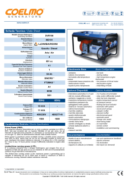
Cushman® Turf Truckster®
With Four Post ROPS
Con roll-bar a quattro montanti
84063 – Kubota® D1105-E3B Diesel Engine, MT
84064 – Kubota® D1105-E3B Diesel Engine, MT, EC
84067 – Suzuki® K6 Gas Engine, MT
84068 – Suzuki® K6 Gas Engine, AT
84069 – Suzuki® K6 Gas Engine, RV and Utility
84063 – Motore Diesel Kubota® D1105-E3B, MT
84064 – Motore Diesel Kubota® D1105-E3B, MT, EC
84067 – Motore Suzuki® K6 a benzina, MT
84068 – Motore Suzuki® K6 a benzina, AT
84069 – Motore Suzuki® K6 a benzina, RV e polifunzionale
WARNING
If incorrectly used, this machine can cause severe injury. Those who use
and maintain this machine should be trained in its proper use, warned of its
dangers and should read the entire manual before attempting to set up,
operate, adjust or service the machine
AVVERTENZA
Questa macchina può causare gravi infortuni se viene utilizzata in modo errato.
Prima di accingersi ad approntare, usare, mettere a punto o eseguire la
manutenzione di questa macchina, coloro che la utilizzano ed i responsabili
della manutenzione devono essere addestrati all’impiego della macchina,
devono essere informati dei pericoli, e devono leggere l’intero manuale.
GB
IT
United
Kingdom
Italy
When Performance Matters.™
FOREWORD
This manual contains adjustment, maintenance,
troubleshooting instructions and parts list for your new
Jacobsen® machine. This manual should be stored with
the equipment for reference during operation.
The serial plate is located on the frame rail under the
steering wheel. Jacobsen recommends you record these
numbers below for easy reference.
CHARLOTTE, NC, USA
1 800 848 1636
Jacobsen.com
Before you operate your machine, you and each operator
you employ should read the manual carefully in its
entirety. By following the safety, operating and
maintenance instructions you will prolong the life of your
equipment and maintain its maximum efficiency.
MODEL
xxxxx
DATE CODE
xxxxx
LABEL # xxxxxxxx
SERIAL #
*xxxxxxxx*
If additional information is needed contact your Jacobsen
Dealer.
Lb/kg W Batt
Nom Power Hp/kw
Suggested Stocking Guide
To Keep your equipment fully operational and productive, Jacobsen suggests you maintain a stock of the more
commonly used maintenance items. We have also included part numbers for additional support materials and training
aids.
❑ Overnight
To order any of the following material:
❑ 2nd Day
1. Write your full name and complete address on your
order form.
3. Order by the quantity desired, the part number, and
the description of the part.
2. Explain where and how to make shipment:
4. Send or bring the order to your authorized Jacobsen
Dealer.
❑ UPS
❑ Regular Mail
Service Parts
Qty. Part No.
4113986
550489
4175560
4117092
5000919
Description
Qty. Part No.
Diesel Engine Oil Filter
Diesel Engine Fuel Filter Element
Diesel Alternator-Power Steering Belt
Diesel Hydraulic Pump Belt
Diesel Engine Air Filter Element
2701908
2701898
4139265
4235370
840352
885249
Description
Gas Engine Oil Filter
Gas Engine Fuel Filter
Gas Alternator-Power Steering Belt
Gas Governor-Hydraulic Pump Belt
Gas Engine Air Filter Element
Hydraulic FIlter Element
Service Support Material
Qty. Part No.
4241725
4241724
4160162
4241728
Description
Qty.
Safety & Operation Manual
Parts & Maintenance
Kubota D1105 Engine Parts Manual
Suzuki K6A Engine Parts Manual
Part No.
4171642
4171675
4171985
4239442
These are the original instructions verified by
Jacobsen A Textron Company
© Copyright 2011, Jacobsen, A Textron Company. “All rights
reserved, including the right to reproduce this material or portions
thereof in any form.”
en-2
Litho in U.S.A. 1-2011
Description
MT Truck Service Manual
AT Truck Service Manual
Suzuki K6A Service Manual
Accessory Manual
Proposition 65 Warning
This product contains or emits
chemicals known to State of California
to cause cancer and birth defects or
other reproductive harm.
Table of Contents
1
1.1
1.2
2
2.1
2.2
3
3.1
3.2
3.3
3.4
3.5
3.6
3.7
3.8
4
4.1
4.2
4.3
4.4
4.5
4.6
4.7
4.8
4.9
4.10
5
5.1
5.2
5.3
5.4
5.5
5.6
5.7
5.8
5.9
5.10
Safety
Operating Safety ........................................ 4
Important Safety Notes .............................. 5
Vehicle Identification Numbers
Vehicle Identification Number .................... 6
Engine Identification Numbers ................... 6
Specifications
Product Identification ................................. 7
Diesel Engine ............................................. 7
Gas Engine ................................................ 7
vehicle ........................................................ 8
Gear Ratios ................................................ 8
Weights and Dimensions ........................... 8
Accessories & Support Literature .............. 9
Declaration of Conformity ........................ 10
Adjustments
General .................................................... 12
Engine Access ......................................... 12
Front Cowl Access ................................... 13
Access Panels ......................................... 13
Diesel Alternator Belt ............................... 14
Diesel Hydraulic Pump Belt ..................... 14
Gas Power Steering - Alternator Belt ....... 14
Gas Hydraulic Pump Belt ......................... 15
Parking Brake Cable ................................ 15
Torque Specification ................................ 16
Maintenance
General .................................................... 17
Engine ...................................................... 17
Engine Oil ................................................ 18
Power Steering Reservoir ........................ 19
Muffler and Exhaust ................................. 19
Engine Overheat Procedure .................... 19
Cooling System ........................................ 20
Air Filter ................................................... 21
Jump Starting ........................................... 21
Battery ..................................................... 22
5.11
5.12
5.13
5.14
5.15
5.16
5.17
5.18
5.19
5.20
5.21
5.22
5.23
5.24
5.25
5.26
5.27
5.28
5.29
5.30
5.31
5.32
6
6.1
7
7.1
7.2
7.3
7.4
7.5
8
9
9.1
9.2
9.3
Charging Battery .......................................22
Hydraulic Hoses ........................................23
Hydraulic Reservoir and Filter ..................23
Fuel ...........................................................24
Fuel System ..............................................24
Tire Pressure ............................................25
Tire Removal and Installation ...................25
Raising the vehicle ....................................26
Towing the Vehicle ...................................27
Governor Oil Level ....................................27
Hydraulic Brakes .......................................28
Differential Fluid ........................................29
Diesel Engine Manual Transmission ........29
Gas Engine Manual Transmission ............30
Gas Engine Automatic Transmission ........30
Electrical System ......................................31
Dash Panel ...............................................31
Headlight Replacement ............................32
Tail Light Replacement .............................32
EFI Diagnostic Check ...............................33
Care and Cleaning ....................................33
Storage .....................................................34
Troubleshooting
General ..................................................... 35
Maintenance & Lubrication Charts
General ..................................................... 36
Lubrication Chart ......................................36
Maintenance Charts ..................................37
Common Replacement Parts ....................38
Kubota Diesel Engine Service Parts .........38
Notes
Parts Catalog
How To Use The Parts Catalog ................ 40
To Order Parts ..........................................40
Table Of Contents .....................................41
en-3
1
SAFETY
1
SAFETY
1.1
OPERATING SAFETY ______________________________________________________
! WARNING
EQUIPMENT OPERATED IMPROPERLY OR BY UNTRAINED PERSONNEL CAN BE DANGEROUS.
Familiarize yourself with the location and proper use of all controls. Inexperienced operators should receive instruction
from someone familiar with the equipment before being allowed to operate the machine.
1. Safety is dependent upon the awareness, concern
and prudence of those who operate or service the
equipment. Never allow minors to operate any
equipment.
2.
It is your responsibility to read this manual and all
publications associated with this equipment (Safety &
Operation Manual, Engine Manual, accessories, and
attachments). If the operator cannot read English it is
the owner’s responsibility to explain the material
contained in this manual to them.
3.
Learn the proper use of the machine, the location and
purpose of all the controls and gauges before you
operate the equipment. Working with unfamiliar
equipment can lead to accidents.
4.
Never allow anyone to operate or service the machine
or its attachments without proper training and
instructions or while under the influence of alcohol or
drugs.
5.
Wear all the necessary protective clothing and
personal safety devices to protect your head, eyes,
ears, hands, and feet. Operate the machine only in
daylight or in good artificial light.
6.
7.
8.
9.
Evaluate the terrain to determine what accessories and
attachments are needed to properly and safely perform
the job. Only use accessories and attachments
approved by Jacobsen.
Stay alert for holes in the terrain and other hidden
hazards.
Inspect the area where the equipment will be used.
Pick up all the debris you can find before operating.
Beware of overhead obstructions (low tree limbs,
electrical wires, etc.) and also underground obstacles
(sprinklers, pipes, tree roots, etc.) Enter a new area
cautiously. Stay alert for hidden hazards.
Never allow anyone near the machine while in
operation. The owner/operator can prevent, and is
responsible for, injuries inflicted to themselves, to
bystanders, and damage to property.
10. Do not carry passengers. Keep bystanders and pets a
safe distance away.
11. Never operate equipment that is not in perfect working
order or is without decals, guards, shields, or other
protective devices securely fastened in place.
12. Never disconnect or bypass any switch.
en-4
13. Do not change the engine governor setting or
overspeed the engine.
14. Carbon monoxide in the exhaust fumes can be fatal
when inhaled. Never operate the engine without proper
ventilation or in an enclosed area.
15. Fuel is highly flammable; handle with care.
16. Keep the engine clean. Allow the engine to cool before
storing and always remove the ignition key.
17. Place transmission in Neutral, depress clutch and
engage parking brake before starting the engine
(motor). Start the engine only when sitting in operator’s
seat never while standing beside the unit.
18. Equipment must comply with the latest federal, state,
and local requirements when driven or transported on
public roads. Watch out for traffic when crossing or
operating on or near roads.
19. Local regulations may restrict the age of the operator.
20. Operate the machine up and down the face of the
slopes (vertically) not across the face (horizontally).
21. To prevent tipping or loss of control do not start or stop
suddenly on slopes. Reduce speed when making
sharp turns. Use caution when changing directions.
22. Always use the seat belt when operating vehicles
equipped with a Roll Over Protective Structure
(ROPS).
Never use a seat belt when operating vehicle
without a ROPS.
Accessory ROPS will continue to be offered for all
equipment currently covered. This allows for the
outfitting of any machines without previous ROPS
installations or replacement of damaged structures.
23. Keep legs, arms, and body inside the seating
compartment while the vehicle is in motion.
24. Always shift transmission to 1st Gear (Manual
Transmission) or Park (Automatic Transmission),
engage parking brake, and stop engine before leaving
the vehicle.
25. Charge batteries in an open well ventilated area away
from spark and flames. Unplug charger before
connecting and disconnecting charger from battery.
Wear protective clothing and use insulated tools.
26. Disconnect the battery cables before performing any
welding operations on this vehicle.
SAFETY
1.2
1
IMPORTANT SAFETY NOTES ________________________________________________
This safety alert symbol is used to alert you to potential hazards.
DANGER - Indicates an imminently hazardous situation which, if not avoided, WILL result in death or serious injury.
WARNING - Indicates a potentially hazardous situation which, if not avoided, COULD result in death or serious
injury.
CAUTION - Indicates a potentially hazardous situation which, if not avoided, MAY result in minor or moderate injury,
and property damage. It may also be used to alert against unsafe practices.
NOTICE - Indicates a potentially hazardous situation which, if not avoided, MAY result in property damage. It may
also be used to alert against unsafe practices.
For pictorial clarity some illustrations in this manual may show shields, guards or plates open or removed. Under no
circumstances should this equipment be operated without these devices securely fastened in place.
! WARNING
The Interlock System on this vehicle prevents the vehicle from starting unless
the clutch pedal is depressed (Manual Transmission) or gear selector is in
Park (P) or Neutral (N) (Automatic Transmission).
NEVER operate vehicle unless the Interlock System is working.
! WARNING
1. Before leaving the operator’s position for any reason:
a. Remove foot from accelerator pedal.
b. Slow vehicle using service brake.
c. Depress clutch and shift transmission to 1st Gear (Manual Transmission, or
Park (Automatic Trnasmission).
d. Engage parking brake.
e. Stop engine and remove the ignition key.
2. Keep hands, feet, and clothing away from moving parts. Wait for all
movement to stop before you clean, adjust or service the machine.
3. Keep the area of operation clear of all bystanders and pets.
4. Never carry passengers unless a seat is provided for them.
By following all instructions in this manual you will prolong the life of your machine and maintain its maximum efficiency.
Adjustments and maintenance should always be performed by a qualified technician.
If additional information or service is needed contact your Authorized Jacobsen Dealer who is kept informed of the
latest methods to service this equipment and can provide prompt and efficient service.
en-5
2
2
2.1
VEHICLE IDENTIFICATION NUMBERS
VEHICLE IDENTIFICATION NUMBERS
VEHICLE IDENTIFICATION NUMBER _________________________________________
The Vehicle Identification Number (VIN), consisting of the
model number, date code, and serial number, is printed
on the Nameplate/Identification Decal attached to the
cross member under the dash.
The serial number is also stamped on the cross member.
It is located to the left of the Nameplate/Identification
Decal.
NOTE: Reference to the Front, Rear, Left, and Right
sides of the vehicle are always determined by the
operator’s seated position.
CHARLOTTE, NC, USA
1 800 848 1636
Jacobsen.com
MODEL
xxxxx
DATE CODE
xxxxx
LABEL # xxxxxxxx
SERIAL #
*xxxxxxxx*
Lb/kg W Batt
Nom Power Hp/kw
Record the Vehicle Identification information below for
easy reference.
Figure 2A
Date Code: _________________________
Always provide the Vehicle Identification Number of the
unit when ordering replacement parts or requesting service
information. Vehicle Identification Numbers must appear
Serial Number: ______________________
on all correspondence concerning this vehicle.
Model Number: ______________________
2.2
ENGINE IDENTIFICATION NUMBERS _________________________________________
The Truckster is equipped with either a Kubota® three
cylinder, diesel powered, liquid cooled, four cycle engine
or a Suzuki® three cylinder gas powered, liquid cooled,
four cycle engine.
The Engine Serial Number for the Kubota engine is on a
plate located on the valve cover.
The Engine Serial Number for the Suzuki engine is
stamped onto the upper engine block on the right side of
the engine under the engine mount and may be partially
hidden by the electrical harness. The serial number is
also hand printed on the fuel rail.
Engine Serial No.
Kubota Diesel
Record the Engine Serial Number below for easy
reference.
Figure 2B
Engine Serial Number: _________________________
Engine Serial No.
K6A Suzuki
en-6
SPECIFICATIONS
3
3
SPECIFICATIONS
3.1
PRODUCT IDENTIFICATION _________________________________________________
84063 ............................Turf Truckster, liquid cooled
diesel engine, 4 speed manual
transmission, 11.16:1 2 speed
differential, mechanical PTO,
and four post ROPS.
84064 ............................Turf Truckster liquid cooled
diesel engine, 4 speed manual
transmission, 11.16:1 2 speed
differential, mechanical PTO,
and four post ROPS. EC
approved.
84067 ............................Turf Truckster liquid cooled gas
engine, 5 speed manual
transmission, 14.21:1 2 speed
3.2
Product
84064
EEC Sound
Power
Operator
Ear
103 dB(A)
84 dB(A)
Vibration M/S2
Arms
Body
2.14
.096
DIESEL ENGINE ___________________________________________________________
Make .............................Kubota
Model ............................D1105-E3B
Horsepower...................26 hp (19.4 kW) @3000 rpm
Note: Actual sustained horsepower will likely be lower
than listed in specifications due to operating limitations
and environmental factors
Displacement ................68.5 cu. in. (1123 cc)
Torque ...........................52.7 ft. lbs. (71.5 Nm) @ 2200
rpm
Fuel:
Type.........................No. 2 Low or Ultra Low Sulfur
Diesel
Rating ......................Cetane Rating-45
Capacity ..................6.55 U.S. Gal. (24.5 liters)
3.3
differential, and four post ROPS.
84068 ............................ Turf Truckster liquid cooled gas
engine, 3 speed automatic
transmission, 14.21:1 2 speed
differential, and four post ROPS.
84069 ............................ Turf Truckster liquid cooled gas
engine, 5 speed manual
transmission, 11.16:1 2 speed
differential, and four post ROPS.
Governor ....................... All Speed Mechanical
Low Idle .................. 1300 RPM
High Idle .................. 3180 RPM
Lubrication:
Capacity .................. 5.4 quarts (5.1 liters)
Below 32° F (0° C) . SAE 10W or 10W-30/10W-40
32-77° F (0-25° C)... SAE 20W or 10W-30/10W-40
Above 77° F (25 ° C)SAE 30W or 10W-30/10W-40
API Classification ... CD or CE
Air Filter......................... Dry type with evacuator valve
Alternator ...................... 60 amp
Cooling System............. Liquid Cooled
Capacity .................. 5.1 qt. (4.8 l) 50/50 water
ethylene glycol mix
GAS ENGINE _____________________________________________________________
Make .............................Suzuki
Model ............................K6
Horsepower...................34 hp (25.35 kW) @ 5000 rpm
Displacement ................40.2 cu. in. (658 cc)
Torque ...........................38.3 ft. lbs. (51.9 Nm) @3200
rpm
Fuel:
Type.........................Unleaded Gasoline
Rating ......................Min. Octane rating 87
Capacity ..................6.55 U.S. Gal. (24.5 liters)
NOTICE
The use of any fuel containing greater than 10%
ethanol may harm the engine's emission control
system and therefore invalidate the emission-related
warranty through the improper action of the operator.
Governor ....................... External Mechanical
Low Idle .................. 950 RPM
High Idle .................. 4450 RPM
Lubrication:
Capacity .................. 3.6 quarts (3.4 liters)
Below 32° F (0° C) . SAE 10W30
32-86° F (0-30° C)... SAE 10W30
Above 86° F (30 ° C)SAE 10W30W or 10W40
API Classification ... SJ
Air Filter......................... Dry type with evacuator valve
Alternator ...................... 60 amp
Cooling System............. Liquid Cooled
Capacity .................. 3.3 qt. (3.0 l) 50/50 water
ethylene glycol mix
Spark Plugs:
NGK 3932 ............... DCPR7E Gap
Denso...................... XU22EPR-U
Gap ......................... 0.032 - 0.035 in. (0.8 - 1.27 mm)
en-7
3
SPECIFICATIONS
3.4
VEHICLE_________________________________________________________________
Tires:
Front ....................... 20 x 10 - 10 Multi Rib
Rear ........................ 24 x 13 -12 Titan Ultra Trac
Tire Pressure:
Front ....................... 20 psi (1.38 BAR)
Rear ........................ 15 - 18 psi (1 - 1.2 BAR)
Battery:
Type ........................ 12 Volt Lead/Acid
Group...................... 24
Service Brake ............... 4 Wheel hydraulic drum brakes
Brake Fluid.............. DOT 3
Parking Brake ............... Integral to rear drum, hand lever
3.5
GEAR RATIOS ____________________________________________________________
84067 Gear Ratios:
5th Gear .................. 1.000:1
4th Gear ................. 1.264:1
3rd Gear ................. 1.908:1
2nd Gear ................. 3.017:1
1st Gear .................. 5.106:1
Reverse .................. 5.151:1
Hypoid Differential... 14.21:1 with 3.2:1 Reduction
84068 Gear Ratios:
3rd Gear ................. 1.000:1
2nd Gear ................. 1.536:1
1st Gear .................. 2.727:1
Reverse .................. 2.222:1
Hypoid Differential... 14.21:1 with 3.2:1 Reduction
3.6
84069 Gear Ratios:
5th Gear...................1.000:1
4th Gear ..................1.264:1
3rd Gear .................1.908:1
2nd Gear..................3.017:1
1st Gear ...................5.106:1
Reverse ...................5.151:1
Hypoid Differential ...11.16:1 with 3.2:1 Reduction
84063 and 84064 Gear Ratios:
4th Gear ..................1.000:1
3rd Gear .................1.423:1
2nd Gear..................1.947:1
1st Gear ...................3.652:1
Reverse ...................3.463:1
Hypoid Differential ...11.16:1 with 3.2:1 Reduction
WEIGHTS AND DIMENSIONS ________________________________________________
Dimensions:
Inches
Length............................................................ 114
Height ...........................................................74.5
Wheel Base .................................................. 58.2
Turning Radius (Outside)...............................242
en-8
actuated
Steering ........................Front wheel power steering
Hitch Capacity:
Max. trailer GVWR.... 1500 lb. (680 kg)
Tounge Weight.......... 200 lb. (90.7 kg)
Vehicle Rated Capacity .. 2850 lb. (1293 kg)
NOTE: When calculating load weight, include 118 lb.
(53.5 kg) for the standard four post ROPS. Do not
exceed Vehicle Rated Capacity.
(mm)
(2897)
(1892)
(1478)
(6146)
Weights:
Lbs.
84063 .......................................................... 1838
84064 .......................................................... 1849
84067 .......................................................... 1690
84068 .......................................................... 1503
84069 .......................................................... 1690
(kg)
(834)
(838)
(766)
(682)
(766)
SPECIFICATIONS
3.7
3
ACCESSORIES & SUPPORT LITERATURE _____________________________________
Contact your area Jacobsen Dealer for a complete listing of accessories and attachments.
! CAUTION
Use of other than Jacobsen authorized parts, excluding emission related components defined in the Emission
Warranty, and accessories may cause personal injury or damage to the equipment.
Flatbeds and Boxes
47 in. Quick Disconnect Flatbed ...........................889983
60 in. Quick Disconnect Flatbed ...........................894769
47 in. Box Assembly (Requires 889983)...............890010
60 in. Box Assembly (Requires 894769).............2703394
Poly Box Assembly ...............................................892530
Box Liner (for 890010) ..........................................888532
Hitches
Fifth Wheel Ball Hitch............................................894690
Receiver Style Drawbar Hitch ............................. 4114386
Flat bar Style Hitch .............................................. 4114566
ROPS Attachments
Upper ROPS (Roll Over Protective Structure) ......894761
Steel Door, Left Side (Requires 894761).............2701303
Steel Door, Right Side (Requires 894761) ..........2701304
Outside Mirrors (Left and Right)............................894768
Rear Window ........................................................894758
Windshield with Wiper...........................................894757
Replacement Four Post ROPS ...........................4205580
NOTE: The four post ROPS equipped as standard
equipment on this vehicle cannot be used with cab
attachments. If an enclosed cab is desired, the four post
ROPS must be replaced with Upper ROPS 894761.
Hydraulic Attachments
High/Low Gas Hydraulics....................................4147940
High/Low Diesel Hydraulics ..................................894713
Implement Lift (A-Frame) ......................................892493
Dry Seal Coupler, 1 set .........................................894604
Hydraulic PTO (Requires 894712 and 894713)....894644
Truck Attachments
Heavy Duty Mechanical PTO.............................. 4112981
Quick Aerator ......................................................2701529
Ram Mount (Sprayer Control Mount) .................. 4119631
1500 Top Dresser................................................2701650
Turn Signal with Right Taillight..............................894764
VICON Spreader (Requires 2701601 or 2701602) ...........
2701600
VICON Hydraulic Power Kit ................................2701601
VICON Mechanical Power Kit .............................2701602
Back-up Alarm ....................................................2703183
Exhaust Spark Arrestor .........................................882574
Heater Defroster ...................................................894760
Support Literature
Safety & Operation Manual.................................4175886
Parts & Maintenance Manual..............................4175887
Suzuki Engine Parts Manual...............................4140632
Kubota Engine Parts Manual ..............................4160162
Service & Repair Manual
en-9
3
SPECIFICATIONS
3.8
DECLARATION OF CONFORMITY ____________________________________________
DECLARATION OF CONFORMITY PROHLÁENÍ O SHOD OVERENSSTEMMELSESERKLÆRING CONFORMITEITSVERKLARING VASTAVUSDEKLARATSIOON VAATIMUSTENMUKAISUUSVAKUUTUS DECLARATION DE CONFORMITE KONFORMITÄTSERKLÄRUNG MEGFELELSÉGI NYILATKOZAT DICHIARAZIONE DI CONFORMITÀ ATBILSTBAS
DEKLAR!CIJA ATITIKTIES DEKLARACIJA DIKJARAZZJONI TAL-KONFORMITÀ DEKLARACJA ZGODNO"CI DECLARAÇÃO DE CONFORMIDADE DECLARA#IE DE CONFORMITATE VYHLÁSENIE O ZHODE IZJAVA O
SKLADNOSTI DECLARACIÓN DE CONFORMIDAD DEKLARATION OM ÖVERENSSTÄMMELSE
Business name and full address of the manufacturer Obchodní jméno a plná adresa výrobce Producentens firmanavn og fulde adresse Bedrijfsnaam en volledig adres van de fabrikant Tootja ärinimi ja täielik aadress Valmistajan toiminimi ja täydellinen osoite Nom commercial et adresse complète du fabricant Firmenname und vollständige Adresse des Herstellers !"#$%& #'()*+ !*'*!& A gyártó üzleti neve és teljes címe Ragione sociale e indirizzo completo del fabbricante Uz,-muma nosaukums un pilna raot/ja adrese Verslo pavadinimas ir pilnas gamintojo adresas Isem kummer0jali u indirizz s1i1 tal-fabbrikant Nazwa firmy i pe3ny adres producenta Nome da empresa e endereço completo do fabricante Denumirea comercial4 5i adresa complet4 a
produc4torului Obchodný názov a úplná adresa výrobcu Naziv podjetja in polni naslov proizvajalca Nombre de la empresa y dirección completa del
fabricante Tillverkarens företagsnamn och kompletta adress
Jacobsen, A Textron Company
11524 Wilmar Blvd.
Charlotte, NC 28273, USA
Product Code ? @
Kód výrobku Produktkode Productcode Toote kood Tuotekoodi Code produit Produktcode E#GL $%MG!%L
Termékkód Codice prodotto Produkta kods Produkto kodas Kodi0i tal-Prodott Kod produktu Código do Produto Cod produs Kód výrobku 84064
Oznaka proizvoda Código de producto Produktkod
Machine Name Z [ Název stroje Maskinnavn Machinenaam Masina nimi Laitteen nimi Nom de la machine Maschinenbezeichnung ]%* +"&!%L Gépnév Denominazione della macchina Iek/rtas nosaukums Mainos pavadinimas Isem talMagna Nazwa urz`dzenia Nome da Máquina Numele echipamentului Názov stroja Naziv stroja Nombre de la máquina Maskinens namn
Diesel Turf Truckster
Designation {| Ozna}ení Betegnelse Benaming Nimetus Tyyppimerkintä Paym~jimas Bezeichnung $!+$*GL Megnevezés Funzione Apzm-jums Lithuanian Denominazzjoni Oznaczenie Designação Specificaie Ozna}enie Namen stroja Descripción Article 13
Beteckning
Serial Number Sériové }íslo Serienummer Serienummer Seerianumber Valmistusnumero Numéro de série Seriennummer '$GL $)GL Sorozatszám Numero di serie S-rijas numurs Serijos numeris Numru Serjali Numer seryjny Número de Série Num4r de
serie Sériové }íslo Serijska tevilka Número de serie Serienummer
8406401651-8406404500
Engine
Motor Motor Motor Mootor Moottori Moteur Motor +"& Modulnév Motore Dzin-js Variklis Sa11a Netta Installata Kubota D1105-E3B
Silnik Motor Motor Motor Motor Motor Motor
en-10
Net Installed Power Z istý instalovaný výkon Installeret nettoeffekt Netto geïnstalleerd vermogen Installeeritud
netovõimsus Asennettu nettoteho Puissance nominale nette Installierte Nettoleistung E)$& '!'*!++ *"(L Nettó beépített teljesítmény Potenza netta installata Paredz-t/ tkla jauda Grynoji galia Wisa tal-Qtug1 Moc zainstalowana netto Potência instalada Puterea instalat4 net4 istý intalovaný výkon Neto vgrajena mo} Potencia instalada neta Nettoeffekt
18,5 kW @ 3200 RPM
Cutting Width | íka ezu Skærebredde Maaibreedte Lõikelaius Leikkuuleveys Largeur de coupe Schnittbreite &%L *L Vágási szélesség Larghezza di taglio Grieanas platums Pjovimo plotis Tikkonforma mad-Direttivi Szeroko cicia Largura de Corte L4imea de t4iere írka záberu irina reza Anchura de corte Klippbredd
NA
Conforms to Directives Spluje podmínky smrnic Er i overensstemmelse med direktiver Voldoet aan de richtlijnen Vastab direktiividele Direktiivien mukainen Conforme aux directives Entspricht Richtlinien %%)&*!' *! !L ]#+'L Megfelel az irányelveknek
Conforme alle Direttive Atbilst direktv/m Atitinka direktyv reikalavimus Valutazzjoni tal-Konformità Dyrektywy zwi`zane Cumpre as Directivas Respect4 Directivele Je v súlade so smernicami Skladnost z direktivami Cumple con las Directivas Uppfyller direktiv
2004/108/EC
2006/42/EC
2000/14/EC, 2005/88/EC
2006/66/EC
Conformity Assessment
Hodnocení plnní podmínek Overensstemmelsesvurdering Conformiteitsbeoordeling Vastavushindamine Vaatimustenmukaisuuden arviointi Evaluation de conformité Konformitätsbeurteilung *!*+ G$ *+L Megfelel¡ség-értékelés Valutazione della conformità Atbilstbas nov-rt-jums Atitikties ¢vertinimas Livell tal-Qawwa tal-£oss Imkejjel Ocena
zgodnoci Avaliação de Conformidade Evaluarea conformit4ii Vyhodnotenie zhodnosti Ocena skladnosti Evaluación de conformidad Bedömning av överensstämmelse
2006/42/EC Annex VIII
Measured Sound Power Level ¤ @
Namený akustický výkon Målte lydstyrkeniveau Gemeten geluidsniveau Mõõdetud helivõimsuse tase Mitattu äänitehotaso Niveau de puissance sonore mesuré Gemessener Schalldruckpegel !)*% ''#% +"+!&L *"(%L Mért hangteljesítményszint Livello di potenza sonora misurato Izm-rtais ska,as jaudas lmenis Imatuotas garso stiprumo lygis Livell tal-Qawwa tal-£oss Iggarantit Moc akustyczna mierzona Nível sonoro medido Nivelul m4surat al puterii
acustice Nameraná hladina akustického výkonu Izmerjena raven zvo}ne mo}i Nivel de potencia sonora medido Uppmätt ljudeffektsnivå
103 dB(A) LWA
Guaranteed Sound Power Level § @
Garantovaný akustický výkon Garanteret lydstyrkeniveau Gegarandeerd geluidsniveau Garanteeritud helivõimsuse tase Taattu äänitehotaso Niveau de puissance sonore garanti Garantierter
Schalldruckpegel +% ''#% +"+!&L *"(%L Szavatolt hangteljesítményszint Livello di potenza sonora garantito Garant-tais ska,as
jaudas lmenis Garantuotas garso stiprumo lygis Livell tal-Qawwa tal-£oss Iggarantit Moc akustyczna gwarantowana Nível sonoro farantido Nivelul garantat al puterii acustice Garantovaná hladina akustického výkonu Zajam}ena raven zvo}ne mo}i Nivel de potencia sonora garantizado Garanterad ljudeffektsnivå
104 dB(A) LWA
Conformity Assessment Procedure (Noise)
@ (@) Postup hodnocení plnní podmínek (hluk) Procedure for overensstemmelsesvurdering (Støj) Procedure van de conformiteitsbeoordeling (geluid) Vastavushindamismenetlus (müra) Vaatimustenmukaisuuden arviointimenettely (Melu) Procédure dévaluation de conformité (bruit) Konformitätsbeurteilungsverfahren (Geräusch) #* ©%G+*+L G$ *+L (ªG$«%L) Megfelel¡ség-értékelési eljárás (Zaj) Procedura di valutazione della conformità (rumore) Atbilstbas nov-rt-juma proced¬ra (troksnis) Atitikties ¢vertinimo proced¬ra (garsas) Pro0edura tal-Valutazzjoni tal-Konformità (£oss) Procedura oceny zgodnoci (poziom ha3asu) Processo de avaliação de conformidade (nível sonoro) Procedura de evaluare a conformit4ii (zgomot) Postup vyhodnocovania zhodnosti (hluk) Postopek za ugotavljanje skladnosti (hrup) Procedimiento de evaluación de conformidad (ruido) Procedur för bedömning av överensstämmelse (buller)
2000/14/EC Annex V
UK Notified Body for 2000/14/EC Z ® 2000/14/¯ Úad certifikovaný podle smrnice }. 2000/14/EC Det britiske bemyndigede organ for 2001/14/EF Engels adviesorgaan voor 2000/14/EG Ühendkuningriigi teavitatud asutus direktiivi 2000/14/EÜ
mõistes Direktiivin 2000/14/EY mukainen ilmoitettu tarkastuslaitos Isossa-Britanniassa Organisme notifié concernant la directive 2000/14/CE Britische benannte Stelle für 2000/14/EG E%%%+%L ]$*GL ±% ²*'% 2000/14/E 2000/14/EK egyesült királyságbeli bejelentett szervezet Organismo Notificato in GB per 2000/14/CE 2000/14/EK AK re´istr-t/ organiz/cija JK notifikuotosios ¢staigos 2000/14/EC Korp Notifikat tar-Renju Unit g1al 2000/14/KE Dopuszczona jednostka badawcza w Wielkiej Brytanii wg 2000/
14/WE Entidade notificada no Reino Unido para 2000/14/CE Organism notificat în Marea Britanie pentru 2000/14/CE Notifikovaný orgán Spojeného kráµovstva pre smernicu 2000/14/ES Britanski priglaeni organ za 2000/14/ES Cuerpo notificado en el Reino Unido para 2000/14/CE Anmält organ för 2000/14/EG i Storbritannien
Number: 1088
Sound Research Laboratories Limited
Holbrook House, Little Waldingfield
Sudbury, Suffolk CO10 0TH
Operator Ear Noise Level @· [@ Hladina hluku v oblasti uí operátora Støjniveau i førers ørehøjde Geluidsniveau oor bestuurder Müratase operaatori kõrvas Melutaso käyttäjän korvan kohdalla Niveau de bruit à hauteur des oreilles de lopérateur Schallpegel am Bedienerohr '#% )%$(«% *' '!%$ A kezel¡ fülénél mért zajszint Livello di potenza sonora allorecchio delloperatore Trok,a lmenis pie operatora auss Dirban}iojo su maina patiriamo triukmo lygis Livell tal-£oss fil-Widna tal-Operatur Dopuszczalny poziom ha3asu dla operatora Nível sonoro nos ouvidos do operador Nivelul zgomotului la urechea operatorului Hladina hluku pôsobiaca na sluch operátora Raven hrupa pri uesu upravljavca Nivel sonoro en el oído del operador Ljudnivå vid förarens öra
84 dB(a) Leq (2006/42/EC)
SPECIFICATIONS
3
Harmonised standards used ¤ · Pouité harmonizované normy Brugte harmoniserede standarder Gebruikte geharmoniseerde standaards Kasutatud ühtlustatud standardid Käytetyt yhdenmukaistetut standardit Normes harmonisées utilisées BS EN ISO 20643
Angewandte harmonisierte Normen $%* $G! % "$+*%%&)+ Harmonizált szabványok Standard armonizzati applicati BS EN ISO 5349-1
Izmantotie saska,otie standarti Panaudoti suderinti standartai Standards armonizzati u¸ati Normy spójne powi`zane Normas harmonizadas usadas
BS EN ISO 5349-2
Standardele armonizate utilizate Pouité harmonizované normy Uporabljeni usklajeni standardi Estándares armonizados utilizados Harmoniserade standarder som används
Technical standards and specifications used ¤ ·|
Pouité technické normy a specifikace Brugte tekniske standarder og specifikationer Gebruikte technische standaards en specificaties Kasutatud tehnilised standardid ja spetsifikatsioonid Käytetyt tekniset standardit ja eritelmät Spécifications et normes techniques utilisées Angewandte technische Normen und Spezifikationen º'" $G! $%#$ L % "$+*%%&)+ M»szaki szabványok és specifikációk Standard tecnici e specifiche applicati Izmantotie tehniskie standarti un specifik/cijas Panaudoti techniniai standartai ir technin~ informacija Standards u spe0ifikazzjonijiet tekni0i u¸ati Normy i specyfikacje techniczne powi`zane Normas técnicas e especificações usadas Standardele tehnice 5i specificaiile utilizate Pouité technické normy a pecifikácie Uporabljeni tehni}ni standardi in specifikacije Estándares y especificaciones técnicas utilizadas Tekniska standarder och specifikationer som används
ISO 2631-1
SAE 21299
The place and date of the declaration ¼ Místo a datum prohláení Sted og dato for erklæringen Plaats en datum van de verklaring Deklaratsiooni väljastamise koht ja kuupäev Vakuutuksen paikka ja päivämäärä Lieu et date de la déclaration Ort und Datum der Erklärung ºG%L +'$%+ #&*+L A nyilatkozat kelte (hely és id¡) Luogo e data della dichiarazione Deklar/cijas vieta un datums Deklaracijos vieta ir data Il-post u d-data tad-dikjarazzjoni Miejsce i data wystawienia deklaracji Local e data da
declaração Locul 5i data declaraiei Miesto a dátum vyhlásenia Kraj in datum izjave Lugar y fecha de la declaración Plats och datum för
deklarationen
Jacobsen, A Textron Company
11524 Wilmar Blvd.
Charlotte, NC 28273, USA
January 1, 2011
Signature of the person empowered to draw up the declaration on behalf of the manufacturer, holds the technical documentation and is authorised to
compile the technical file, and who is established in the Community.
{ |
, @ , ½ ¾ ·|
@ ·|
½ ®.
Podpis osoby oprávnné sestavit prohláení jménem výrobce, dret technickou dokumentaci a osoby oprávnné sestavit technické soubory a zaloené v
rámci Evropského spole}enství.
Underskrift af personen, der har fuldmagt til at udarbejde erklæringen på vegne af producenten, der er indehaver af dokumentationen og er bemyndiget til
at udarbejde den tekniske journal, og som er baseret i nærområdet.
Handtekening van de persoon die bevoegd is de verklaring namens de fabrikant te tekenen, de technische documentatie bewaart en bevoegd is om het
technische bestand samen te stellen, en die is gevestigd in het Woongebied.
Ühenduse registrisse kantud isiku allkiri, kes on volitatud tootja nimel deklaratsiooni koostama, kes omab tehnilist dokumentatsiooni ja kellel on õigus
koostada tehniline toimik.
Sen henkilön allekirjoitus, jolla on valmistajan valtuutus vakuutuksen laadintaan, jolla on hallussaan tekniset asiakirjat, joka on valtuutettu laatimaan
tekniset asiakirjat ja joka on sijoittautunut yhteisöön.
Signature de la personne habilitée à rédiger la déclaration au nom du fabricant, à détenir la documentation technique, à compiler les fichiers techniques et
qui est implantée dans la Communauté.
Unterschrift der Person, die berechtigt ist, die Erklärung im Namen des Herstellers abzugeben, die die technischen Unterlagen aufbewahrt und berechtigt
ist, die technischen Unterlagen zusammenzustellen, und die in der Gemeinschaft niedergelassen ist.
¿%$ & !G% '©%*%#%!+% !+ *(!©+ !+L #&*+L ' $%L !% !*'*!&, % %%%L !"' !+ !'"& )'*+ "' !+
'©%*%#G!+*+ !©%&*' !% !'"G '% % %%%L ' #%$*%L *!+ E%G!+!.
A gyártó nevében meghatalmazott személy, akinek jogában áll módosítania a nyilatkozatot, a m»szaki dokumentációt ¡rzi, engedéllyel rendelkezik a
m»szaki fájl összeállításához, és aki a közösségben letelepedett személy.
Firma della persona autorizzata a redigere la dichiarazione a nome del fabbricante, in possesso Della documentazione tecnica ed autorizzata a costituire
il fascicolo tecnico, che deve essere stabilita nella Comunità.
T/s personas paraksts, kura ir pilnvarota deklar/cijas sast/danai raot/ja v/rd/, kurai ir tehnisk/ dokument/cija, kura ir pilnvarota sagatavot tehnisko
re´istru un kura ir apstiprin/ta Kopien/.
Asmuo, kuris yra gana inomas, kuriam gamintojas suteik~ ¢galiojimus sudaryti i` deklaracij`, ir kuris j` pasira~, turi vis` technin informacij` ir yra
¢galiotas sudaryti technin~s informacijos dokument`.
Il-firma tal-persuna awtorizzata li tfassal id-dikjarazzjoni fisem il-fabbrikant, g1andha d-dokumentazzjoni teknika u hija awtorizzata li tikkompila l-fajl
tekniku u li hija stabbilita fil-Komunità.
Podpis osoby upowa¸nionej do sporz`dzenia deklaracji w imieniu producenta, przechowuj`cej dokumentacj techniczn`, upowa¸nion` do stworzenia
dokumentacji technicznej oraz wyznaczonej ds. wspólnotowych.
Assinatura da pessoa com poderes para emitir a declaração em nome do fabricante, que possui a documentação técnica, que está autorizada a compilar
o processo técnico e que está estabelecida na Comunidade.
Semn4tura persoanei împuternicite s4 elaboreze declaraia în numele produc4torului, care deine documentaia tehnic4, este autorizat4 s4 compileze
dosarul tehnic 5i este stabilit4 în Comunitate.
Podpis osoby poverenej vystavením vyhlásenia v mene výrobcu, ktorá má technickú dokumentáciu a je oprávnená spracovaÀ technické podklady a ktorá
je umiestnená v Spolo}enstve.
Podpis osebe, poobla}ene za izdelavo izjave v imenu proizvajalca, ki ima tehni}no dokumentacijo in lahko sestavlja spis tehni}ne dokumentacije, ter ima
sede v Skupnosti.
Firma de la persona responsable de la declaración en nombre del fabricante, que posee la documentación técnica y está autorizada para recopilar el
archivo técnico y que está establecido en la Comunidad.
Undertecknas av den som bemyndigad att upprätta deklarationen å tillverkarens vägnar, innehar den tekniska dokumentationen och är bemyndigad att
sammanställa den tekniska informationen och som är etablerad i gemenskapen.
Certificate Number Z
íslo osvd}ení Certifikatnummer Certificaatnummer Sertifikaadi number Hyväksyntänumero Numéro de certificat Bescheinigungsnummer $)GL Á*!%%+!%( Hitelesítési szám Numero del certificato Sertifik/ta numurs Sertifikato numeris Numru ta0-Âertifikat Numer certyfikatu Número do Certificado Num4r certificat íslo osved}enia tevilka certifikata Número de certificado Certifikatsnummer
2006/42/EC Annex II 1.A.2
Tim Lansdell
Technical Director
Ransomes Jacobsen Limited
West Road, Ransomes Europark,
Ipswich, IP3 9TT, England
2006/42/EC Annex II 1.A.10
Vasant Godhalekar
VP of Engineering
Jacobsen, A Textron Company
11524 Wilmar Blvd,
Charlotte, NC 28273, USA
4175887 Rev B
GB
BG
CZ
DK
NL
EE
FI
FR
DE
GR
HU
English
български
čeština
dansk
Nederlands
eesti
suomi
français
Deutsch
Ελληνικά
magyar
IT
LV
LT
MT
PL
PT
RO
SK
italiano
latviešu
valoda
lietuvių
kalba
Malki
polski
português
Română
slovenčina
SI
slovenščina
ES
SE
Ελληνικά
Svenska
en-11
4
4
ADJUSTMENTS
ADJUSTMENTS
4.1
GENERAL________________________________________________________________
! WARNING
To prevent injury, depress clutch pedal and shift
transmission to Neutral, engage parking brake, stop
engine, and remove key from ignition switch before
making any adjustments or performing maintenance.
2. Replace, do
components.
not
adjust,
worn,
or
damaged
3. Long hair, jewelry, or loose fitting clothing may get
tangled in moving parts.
! CAUTION
Make sure the vehicle is parked on a solid and level
surface. Never work on a vehicle that is supported
only by the jack. Always use jack stands.
Be careful to prevent entrapment of the hands and
fingers between moving and fixed components of the
machine.
If only the front or rear of the vehicle is raised, place
chocks in front of and behind the wheels that are not
raised.
4. Do not change governor settings or overspeed the
engine.
1. Adjustments and maintenance should always be
performed by a qualified technician. If proper
adjustment cannot be made, contact an authorized
Cushman Dealer.
4.2
5.
Keep hands and feet away from moving parts. If
possible do not make adjustments with the engine
running.
ENGINE ACCESS__________________________________________________________
Never remove or install the engine cover while the engine
is running. The engine cover is a machinery guard and its
removal exposes you to moving parts. Keep hands, hair,
and clothing away from flywheel, radiator cooling fan,
alternator fan, engine belts, pulleys, and air intake.
! WARNING
Keep clothing, hands, and hair away from moving
parts. These items could become entangled, causing
serious personal injury.
Engine Cover
Latch
For servicing the engine and related components, the
engine cover can be tilted forward or removed.
To gain access to the engine, unlock key-lock if installed,
push the engine cover latch towards the rear of the unit
and tilt cover forward.
Figure 4A
When replacing the engine cover, make sure the
retaining tabs located at the front corners of the engine
cover are inserted into the slots in the floorboard. Tilt seat
to the rear until the engine latch engages. Lock key-lock
if equipped.
! WARNING
Retaining Tab
In Slot On
Floor board
Failure to latch the seat properly can result in the
engine cover tipping forward causing loss of control of
the vehicle and possible personal injury.
Figure 4B
en-12
ADJUSTMENTS
4.3
4
FRONT COWL ACCESS_____________________________________________________
The front cowl opens to gain access to two access
panels, fuse panel, horn, and master cylinder reservoir.
Pull Lever
To Release
Cowl Latc h
To open the front cowl locate the release lever at the
upper left corner of front clip near the left side headlight.
Pull the lever toward the headlight to release the front
cowl latch and at the same time pull up on the front cowl.
Front Cowl
Release Lever
Fully open the cowl and allow it to rest on the steering
wheel (or upper ROPS structure if installed).
The front cowl will not spring up when the release lever is
pulled and so must be lifted manually.
Figure 4C
4.4
ACCESS PANELS _________________________________________________________
There are two access panels located under the front cowl
and one located in the middle of the floorboard.
Remove panel (A) under cowl to access the shifter
linkage and wiring for the instrument panel.
A
Remove panel (B) under cowl to access the front
suspension.
Remove the center panel (C) in the middle of floorboard
to access the throttle cable, accelerator pedal linkage,
wire harness, and rear hydraulic brake line.
NOTE: It will be necessary to remove the accelerator
pedal in order to completely remove the center floorboard
panel.
B
Figure 4D
C
Figure 4E
en-13
4
ADJUSTMENTS
4.5
DIESEL ALTERNATOR BELT ________________________________________________
Inspect and adjust new belt after first 24-48 hours of
operation. Adjust every 200 hours thereafter.
Adjust alternator pulley so belt deflects 1/4 to 1/2 in. (6 to
12 mm) with a 20 lb. push at midpoint between water
pump and alternator pulleys.
D
If tension is incorrect loosen alternator mounting bolts (D)
and adjust alternator until proper belt tension is achieved.
Figure 4F
4.6
DIESEL HYDRAULIC PUMP BELT ____________________________________________
Inspect and adjust new belt after first 24-48 hours of
operation. Adjust every 200 hours thereafter.
Adjust hydraulic pump belt so belt deflects 1/4 to 1/2 in.
(6 to 12 mm) with a 20 lb. push at midpoint between
pulleys.
If tension is incorrect loosen pump mounting bolts (E)
and carefully pry pump away from the engine until proper
belt tension is achieved.
E
Figure 4G
4.7
GAS POWER STEERING - ALTERNATOR BELT ________________________________
Inspect and adjust new belt after first 24-48 hours of
operation. Adjust every 200 hours thereafter.
Adjust power steering pump so belt deflects 1/4 to 1/2 in.
(6 to 12 mm) with a 39 lb. push at midpoint between
pulleys.
If tension is incorrect loosen power steering pump
mounting bolts (F) and carefully pry pump away from the
engine until proper belt tension is achieved.
F
Figure 4H
en-14
ADJUSTMENTS
4.8
4
GAS HYDRAULIC PUMP BELT _______________________________________________
Inspect new belt after first 24-48 hours of operation.
Belt is dynamically adjusted with a spring loaded
tensioner to 12 ft-lbs. No adjustment is required.
To remove belt rotate tensioner towards radiator to
release tension and remove belt from pulleys.
Figure 4I
4.9
PARKING BRAKE CABLE ___________________________________________________
1. Remove the engine cover. Put chocks in front of and
behind at least two wheels at opposite corners of
vehicle.
2. Engage parking brake. If handle is at an angle
greater than 45° to the panel, adjustment is
required.
3. Disengage parking brake.
4. Tighten adjustment nut (G) a couple of turns.
5. Engage parking brake. Repeat steps 3 and 4 until
handle is at an approximate 45° angle when parking
brake is engaged.
G
Figure 4J
en-15
4
ADJUSTMENTS
4.10 TORQUE SPECIFICATION___________________________________________________
NOTICE
All torque values included in these charts are approximate and are for reference only. Use of these torque values is
at your sole risk. Cushman is not responsible for any loss, claim, or damage arising from the use of these charts.
Extreme caution should always be used when using any torque value.
Jacobsen uses Grade 5 (Inch) or Grade 8.8 (Metric) bolts as standard, unless otherwise noted.
AMERICAN NATIONAL STANDARD FASTENERS
AMERICAN NATIONAL STANDARD FASTENERS
SIZE
SIZE
UNITS
GRADE 5
GRADE 8
UNITS
GRADE 5
GRADE 8
#6-32
in-lbs (Nm)
20 (2.3)
–
7/16-14
ft-lbs (Nm)
50 (67.8)
65 (88.1)
#8-32
in-lbs (Nm)
24 (2.7)
30 (3.4)
7/16-20
ft-lbs (Nm)
55 (74.6)
70 (94.9)
#10-24
in-lbs (Nm)
35 (4.0)
45 (5.1)
1/2-13
ft-lbs (Nm)
75 (101.7)
100 (135.6)
#10-32
in-lbs (Nm)
40 (4.5)
50 (5.7)
1/2-20
ft-lbs (Nm)
85 (115.3)
110 (149.2)
#12-24
in-lbs (Nm)
50 (5.7)
65 (7.3)
9/16-12
ft-lbs (Nm)
105 (142.4)
135 (183.1)
1/4-20
in-lbs (Nm)
95 (10.7)
125 (14.1)
9/16-18
ft-lbs (Nm)
115 (155.9)
150 (203.4)
1/4-28
in-lbs (Nm)
95 (10.7)
150 (17.0)
5/8-11
ft-lbs (Nm)
150 (203.4)
195 (264.4)
5/16-18
in-lbs (Nm)
200 (22.6)
270 (30.5)
5/8-18
ft-lbs (Nm)
160 (217.0)
210 (284.8)
5/16-24
in-lbs (Nm)
240 (27.1)
300 (33.9)
3/4-10
ft-lbs (Nm)
170 (230.5)
220 (298.3)
3/8-16
ft-lbs (Nm)
30 (40.7)
40 (54.2)
3/4-16
ft-lbs (Nm)
175 (237.3)
225 (305.1)
3/8-24
ft-lbs (Nm)
35 (47.5)
45 (61.0)
7/8-14
ft-lbs (Nm)
300 (406.8)
400 (542.4)
METRIC FASTENERS
SIZE
UNITS
4.8
5.8
8.8
10.9
12.9
Non Critical
Fasteners
into
Aluminum
M4
Nm (in-lbs)
1.2 (11)
1.7 (15)
2.9 (26)
4.1 (36)
5.0 (44)
2.0 (18)
M5
Nm (in-lbs)
2.5 (22)
3.2 (28)
5.8 (51)
8.1 (72)
9.7 (86)
4.0 (35)
M6
Nm (in-lbs)
4.3 (38)
5.7 (50)
9.9 (88)
14.0 (124)
16.5 (146)
6.8 (60)
M8
Nm (in-lbs)
10.5 (93)
13.6 (120)
24.4 (216)
33.9 (300)
40.7 (360)
17.0 (150)
M10
Nm (ft-lbs)
21.7 (16)
27.1 (20)
47.5 (35)
66.4 (49)
81.4 (60)
33.9 (25)
M12
Nm (ft-lbs)
36.6 (27)
47.5 (35)
82.7 (61)
116.6 (86)
139.7 (103)
61.0 (45)
M14
Nm (ft-lbs)
58.3 (43)
76.4 (55)
131.5 (97)
184.4 (136)
219.7 (162)
94.9 (70)
en-16
MAINTENANCE
5
5
MAINTENANCE
5.1
GENERAL ________________________________________________________________
lubricated.
! WARNING
Before you clean, adjust, or repair this equipment,
depress clutch pedal and shift transmission to Neutral,
engage parking brake, stop engine, and remove key
from ignition switch to prevent injuries.
Make sure the vehicle is parked on a solid and level
surface. Never work on a vehicle that is supported
only by a jack. Always use jack stands.
1. Adjustment and maintenance should always be
performed by a qualified technician. If proper
adjustments cannot be made contact an Authorized
Cushman Dealer.
2.
Inspect the equipment on a regular basis, establish a
maintenance schedule, and keep detailed records.
5.2
a.
Keep the equipment clean.
b.
Keep all moving parts properly adjusted and
c.
Replace worn or damaged parts before operating
the machine.
d.
Keep all fluids at their proper levels.
e.
Keep shields in place and all hardware securely
fastened.
f.
Keep tires properly inflated.
3.
Long hair, jewelry, or loose fitting clothing may get
tangled in moving parts.
4.
Use the illustrations in the Parts & Maintenance
Manual as reference for the disassembly and
assembly of components.
5.
Recycle or dispose of all hazardous materials
(batteries, fuel, lubricants, anti-freeze, etc.) according
to federal, state, and local regulations.
6.
Keep hands and feet away from moving parts.
Whenever possible do not make adjustments with the
engine running.
ENGINE _________________________________________________________________
IMPORTANT: A separate Engine Manual, prepared by
the engine manufacturer, is supplied with this vehicle.
Read the Engine Manual carefully until you are familiar
with the operation and maintenance of the engine.
Proper attention to the engine manufacturer’s directions
will assure maximum service life of the engine. To order
replacement engine manuals contact the engine
manufacturer.
4. Check and adjust hydraulic pump and alternator
belts. See Sections 4.5, 4.6, 4.7 and 4.8.
The proper break-in of a new engine can make a
considerable difference to the performance and life of the
engine.
Keep your engine clean. If dirt has accumulated on the
engine it should be washed with a nonflammable solvent
or strong detergent.
NOTICE
When washing becomes necessary it can be carried out
concurrent with servicing the vehicle.
The vehicle is designed to operate most efficiently at
the preset governor setting. Do not change the engine
governor settings or overspeed the engine.
During the break-in period Jacobsen recommends the
following:
5. Refer to Section 7.3 and Engine Manual for specific
maintenance intervals.
6. If the injection pump, injectors, or the fuel system
require service contact an authorized Jacobsen
Dealer.
In order to maintain reliable service from your engine a
regular check-up and maintenance schedule should be
followed. Proper maintenance will prolong the engine’s
life and avoid premature overhaul.
1. During the first 50 hours of operation a new engine
should be allowed to reach an operating temperature
of at least 140°F (60°C) prior to operation at full load.
2. Check the engine oil level twice daily during the first
50 hours of operation. Higher than normal oil
consumption is not uncommon during the break-in
period.
3. Change engine oil and oil filter element after first 35
hours of operation.
en-17
5
MAINTENANCE
5.3
ENGINE OIL ______________________________________________________________
Check the engine oil at the start of each day before
starting the engine.
To check the engine oil remove the dipstick and wipe it
with a clean rag. Reinsert the dipstick until it contacts the
oil tube. Remove the dipstick and read the oil level.
Oil Level Must
Be
Between
Marks
Engine
Dipstick
DO NOT OVERFILL
The oil level should always be between the ADD and
FULL mark on the dipstick. If oil level is below the ADD
mark remove the filler cap and add oil to bring the level
up between marks. Do Not Overfill.
NOTE: If the engine has recently been running allow time
(with engine turned off) to let the oil settle to obtain an
accurate oil level reading.
Diesel Engine: Use only
classification CD or CE.
engine
oils
with
Diesel
Engine
ADD
FULL
ADD
API
Gas
Engine
Gas Engine: Use only engine oils with API classification
SJ.
Using oil other than the service class listed or oil change
intervals longer than recommended could reduce engine
life. Damage to engine due to improper maintenance or
use of incorrect oil quality and/or viscosity is not covered
by the engine warranty.
Diesel Engine: Perform initial oil change after first 35
hours of operation and every 75 hours or two months
thereafter. See Engine Manual.
Gas Engine: Perform initial oil change after first 50 hours
of operation and every 100 hours or three months
thereafter. See Engine Manual.
Significant oil loss can damage the engine. Considerable
oil loss could be due to a loose or incorrectly installed
drain plug, cracked gaskets, or a loose oil filter.
Drain plugs are located beneath the engine in the oil pan.
Remove both plugs when changing the oil.
Check drain plugs and oil for metal chips that could
indicate engine damage. Immediately replace drain plugs
with damaged gasket surfaces.
After oil has completely drained clean excess oil from oil
pan and drain plugs. Install drain plugs and tighten
securely. Refer to Engine Manual for proper torque.
Always replace the engine oil filter when changing the
engine oil. Apply a light coat of engine oil to the rubber
gasket surface of new filter before installing.
Diesel Engine: Fill Kubota engine with approximately 5.4
qts. (5.1 l) of clean engine oil. Check oil level and add
additional oil if required.
Gas Engine: Fill Suzuki engine with approximately 3.6
qts. (3.4 l) of clean engine oil. Check oil level and add
additional oil if required.
en-18
FULL
Figure 5A
Kubota Diesel
SAE 10W/10W-30
SAE 20W/10W-30
SAE 30W/10W-30
Suzuki Gas
SAE 10W-30 for all temperature ranges
°F
-20
°C -30
0
-20
20 32 40
-10
0
10W-40
60
10
7780
20 25 30
100
40
Figure 5B
Diesel Engine:
Above 77°F (25°C)
SAE 30W or SAE10W30/10W40
32 to 77°F (0 to 25°C)
SAE 20W or SAE 10W30/10W40
Below 32° (0°C)
SAE10W or SAE 10W30/10W40
Gas Engine:
All
ranges
temperature SAE 10W30
Above 85° F (29° C)
SAE 10W 40
Replacement Oil Filters
Kubota Diesel
4113986
Suzuki Gas
2701908
MAINTENANCE
5.4
5
POWER STEERING RESERVOIR _____________________________________________
! WARNING
Before servicing or doing any maintenance work
around the engine area make sure the engine has had
time to cool. Serious burns can result if the engine or
surrounding surfaces are hot.
When checking the fluid level before the engine has been
warmed up the level should be at the COLD mark on the
dipstick. After the engine has been warmed up and the
fluid is warm the level should be between the COLD and
HOT marks. Use General Motors® Power Steering Fluid
as required to bring fluid up to proper level.
The power steering reservoir is located on the right side
of the engine below the alternator.
HOT
FULL
COLD
ADD
The level in the reservoir should be checked after the first
35 and again at 70 hours. After that the level should be
checked every 100 hours.
Power Steering Dipstick
Figure 5C
5.5
MUFFLER AND EXHAUST___________________________________________________
! WARNING
Exhaust fumes contain carbon monoxide that is toxic
and can be fatal when inhaled.
NEVER operate an engine without proper ventilation.
To protect from carbon monoxide poisoning inspect the
complete exhaust system regularly and always replace a
defective muffler.
If you notice a change in the color or sound of the
exhaust stop the engine immediately. Identify the
problem and have the system repaired.
Torque all exhaust manifold hardware evenly. Tighten or
replace exhaust clamps.
5.6
ENGINE OVERHEAT PROCEDURE ___________________________________________
During vehicle operation if the water temperature gauge
shows 230° F (110° C) or above and/or the overheat
warning buzzer sounds follow this procedure.
1. Stop the vehicle. DO NOT shut the engine off.
Place vehicle in Neutral and engage the parking
brake.
2. Immediately disengage any accessories that are
operating.
3. Slow the engine speed to a fast idle.
4. Remove any dirt, chaff, debris, etc. from the radiator
intake screen located on the right side of the
vehicle.
! CAUTION
Temperature gauge needle should start to go down
approximately 30 seconds after the screen is cleaned. If
temperature does not go down STOP the engine and
check the following:
1. Check to see if cooling fan is operating. Fan should
be turning with coolant above 180° F (82° C) on
diesel units or 208° F (97.7° C) on gas units even
with ignition switch in OFF position.
2. Check engine oil level.
3. Check for a leak in the cooling system. Do not open
radiator when hot. Check coolant levels after system
completely cools.
Failure to heed the overheat warning and properly
maintain the cooling system will cause permanent engine
damage.
Be careful when opening the engine access cover or
cleaning the intake screen. Metal surfaces near the
radiator and engine may be hot to the touch. Use a
brush or gloves to clean screen.
en-19
5
MAINTENANCE
5.7
COOLING SYSTEM ________________________________________________________
This vehicle is equipped with a radiator, temperature
controlled fan, temperature gauge, and an overheat
buzzer.
2. Drain and refill cooling system every 400 hours or 9
months, whichever comes first. Allow system to cool
before draining.
a. Remove the cooling fan fuse
! WARNING
To prevent serious bodily injury from hot coolant or
steam blow-out, never attempt to remove the radiator
cap while the engine is running. Stop the engine and
wait several hours until it is cool. Even then, use
extreme care when removing the cap.
! CAUTION
Do not pour cold water into a hot radiator. Do not
operate engine without a proper coolant mixture.
Install cap and tighten securely.
! WARNING
The cooling fan is controlled by a temperature switch
and may start at any time coolant temperature is
above 150° F (65 ° C), even with the ignition switch in
the OFF position. Do not attempt to service the
cooling system without first disconnecting the
negative battery cable or removing the fan fuse.
NEVER add straight antifreeze to the radiator. Mix equal
amounts of clean water with ethylene glycol based antifreeze in a separate container before adding it to the
cooling system. Do not use a mixture of more than 50%
antifreeze.
Always recycle or dispose of used antifreeze in a
responsible manner. Used antifreeze can be harmful to
the environment.
1. Check coolant level daily. Radiator should be full and
recovery bottle should be up to the cold mark.
a. Tilt engine cover forward to gain access to the
radiator.
b. With the engine stopped and cool, remove
radiator cap and check coolant level. The coolant
level should be at or within 1/4 in. (6 mm) of the
filler port. Fill with a 50/50 antifreeze/water
mixture if required.
c.
en-20
Visually check the reservoir tank. Coolant level
should be at or above FULL line but less than
4 in. (102 mm). Add a 50/50 antifreeze/water
mixture if required.
b. Remove the radiator cap.
c.
Open the engine block drain and the radiator
drain. Remove lower radiator hose. Close both
drains and install lower radiator hose once
system has completely drained.
d. Empty and clean the recovery bottle.
e. Fill radiator to the bottom of the filler neck with
50/50 antifreeze/water mixture.
f.
Fill recovery bottle to full mark with 50/50
antifreeze/water mixture.
3. Keep radiator air passages clean. Use compressed
air (30 psi maximum) to clean the fins. Water left
between the fins will collect dirt and reduce the
amount of air flow to properly cool the engine.
4. To provide proper air flow, do not obstruct the air
intake screen on the right side of the vehicle. Keep
screen clean.
5. Replace clamps and hoses every two years.
6. If you have to add coolant more than once a month,
or add more than one quart at a time, have a
authorized Cushman Dealer check the cooling
system.
MAINTENANCE
5.8
5
AIR FILTER _______________________________________________________________
Do not remove the element for inspection or cleaning.
Unnecessary removal of the filter increases the risk of
injecting dust and other impurities into the engine.
When service is required first clean the outside of the
filter housing, then remove the old element as gently as
possible and discard.
1. Carefully clean the inside of the filter housing without
allowing dust into the air intake.
2. Inspect the new element. Do not use a damaged
element and never use an incorrect element.
3. Assemble the new element and make sure it seats
properly.
4. Reassemble cap making sure it seals completely
around the filter housing. Dust evacuator (A) must
be facing down.
5. Unsnap retaining clamps and remove the old
element as gently as possible and discard.
6. Carefully clean the inside of the filter housing
without allowing dust into the air intake.
7. Inspect the new element. Do not use a damaged
element and never use an incorrect element.
8. Assemble the new element and make sure it seats
properly.
9. Assemble cap making sure it seals completely
around the filter housing. Dust evacuator (A) must
be facing down.
10. Install air cleaner assembly into the vehicle. Secure
with hardware (B).
11. Connect both hoses and tighten hose clamps.
5. Check all hoses and air ducts. Tighten hose clamps.
Gas Engine
Replacement (Diesel Only)
1. Clean the outside of the filter housing, especially
around hose connections and cover.
A
2. Note location of hoses. Loosen hose clamps and
remove both hoses from air cleaner. Use caution to
prevent dust or other debris from entering engine
intake hose.
A
3. Remove air cleaner mounting hardware (B). Air filter
is secured with a single screw and nut.
4. Lift the air cleaner assembly out of the vehicle.
5.9
Diesel Engine
JUMP STARTING __________________________________________________________
Before attempting to jump start the vehicle check the
condition of the discharged battery.
Engage parking brake of both vehicles, shift transmission
to Neutral and turn off all electrical loads.
! WARNING
Batteries generate explosive hydrogen gas. To reduce
the chance of an explosion avoid creating sparks near
battery. Always connect the Negative jumper cable to
the frame of the vehicle with the discharged battery
away from the battery.
When connecting jumper cables:
1. Stop the engine on the vehicle with a good battery.
2. Connect RED jumper cable to the Positive (+)
terminal on the good battery and to the Positive (+)
terminal on the discharged battery.
3. Connect the BLACK jumper cable from the Negative
(-) terminal on the good battery to the frame of the
vehicle with the discharged battery.
After cables have been connected start the engine on the
vehicle with the good battery then start the vehicle with
the discharged battery.
en-21
5
MAINTENANCE
5.10 BATTERY ________________________________________________________________
Make absolutely certain the ignition switch is OFF and
the key has been removed before servicing the battery.
! CAUTION
Always use insulated tools, wear protective glasses or
goggles, and protective clothing when working with
batteries. You must read and obey all battery
manufacturer’s instructions.
Tighten cables securely to battery terminals and apply a
light coat of silicone dielectric grease to terminals and
cable ends to prevent corrosion. Keep vent caps and
terminal covers in place.
Keep the top of the battery clean and free of corrosion by
washing battery with a solution of baking soda and water.
Rinse with clean water.
1. When installing the battery, always assemble the
Positive (RED) (+) battery cable first and the
Negative (BLACK) (-) battery cable last.
2. When removing the battery, always remove the
Negative (BLACK) (-) battery cable first and Positive
(RED) (+) battery cable last.
3. Make sure battery is properly installed and secured
to the battery tray.
! WARNING
Battery posts, terminals, and related accessories
contain lead and lead compounds, chemicals known
to the State of California to cause cancer and
reproductive harm. Wash your hands after
handling.
Verify battery polarity before connecting or disconnecting
the battery cables.
5.11 CHARGING BATTERY _____________________________________________________
! WARNING
Charge battery in a well ventilated area. Batteries
generate explosive gases. To prevent an explosion
keep any device that may create sparks or flames
away from the battery.
To prevent injury stand away from battery when the
charger is turned on. A damaged battery could
explode.
1. Refer to Section 5.10. Read the Battery’s and
Charger’s manuals for specific instructions.
2. Whenever possible remove the battery from the
vehicle before charging. If battery is not sealed
check that the electrolyte covers the plates in all the
cells.
Battery cables must be disconnected before using a fast
charger or damage to the alternator may result.
3. Make sure the charger is Off. Then connect the
charger to the battery terminals as specified in the
charger’s manual.
4. Always turn the charger Off before disconnecting
charger from the battery terminals.
en-22
MAINTENANCE
5
5.12 HYDRAULIC HOSES _______________________________________________________
! WARNING
To prevent serious injury from hot, high pressure oil
never use your hands to check for oil leaks; use paper
or cardboard.
Hydraulic fluid escaping under pressure can have
sufficient force to penetrate skin. If fluid is injected into
the skin it must be surgically removed within a few
hours by a doctor familiar with this form of injury or
gangrene may result.
IMPORTANT: The hydraulic system can be
permanently damaged if the oil becomes
contaminated. Before disconnecting any hydraulic
component clean the area around the fittings and the
hose ends to keep impurities out of the system.
a. Before disconnecting any hydraulic component
tag or mark the location of each hose then clean
the area around the fittings.
b. As you disconnect the component be prepared to
assemble plugs or caps to the hose ends and
open ports. This will keep impurities out of the
hydraulic system and also prevent oil spills.
1. Always disengage all drives, engage parking brake,
stop engine, and remove key before inspecting or
disconnecting hydraulic lines or hoses.
c.
2. Check visible hoses and tubes daily. Look for wet
hoses or oil spots. Replace worn or damaged hoses
and tubes before operating the machine.
d. Keep the hose from twisting. Twisted hoses can
cause couplers to loosen as the hose flexes
during operation resulting in oil leaks.
3. The replacement tube or hoses must be routed in
the same path as the existing hose. Do not move
clamps, brackets, and ties to a new location.
e. Kinked or twisted hoses can restrict the oil flow
causing the system to malfunction, the oil to
overheat and also lead to hose failure.
4. Thoroughly inspect all tubes,
connections every 250 hours.
hoses,
Make sure O-rings are clean and hose fittings
are properly seated before tightening.
and
5.13 HYDRAULIC RESERVOIR AND FILTER ________________________________________
Refer to Section 7.3 for specific maintenance intervals.
To replace hydraulic oil filter:
Normally the hydraulic system will not need additional
fluid. Sometimes a leak may develop causing the system
to require repair and refilling. If you notice hydraulic fluid
escaping when the system is being used or if a leak is
suspected turn off all hydraulic functions and stop
the engine.
1. Remove the old filter.
Periodically check the hydraulic fluid level (hydraulic level
should be checked every 100 hours of operation). Loss
of fluid can signal a small leak before it becomes worse.
4. Check hydraulic oil level and fill with GreensCare 68
to knurled mark on gauge.
2. Fill new filter with GreensCare 68 fluid then install
new filter. Hand tighten only.
3. Operate engine at idle speed with hydraulic system
in Neutral for five minutes.
To check the fluid level:
1. Place vehicle on a flat and level surface. Fully lower
any accessory attachment, including the dump box.
Stop the vehicle engine.
2. Remove the dipstick/breather tube from the top of
the tank. Wipe the dipstick then place in tank with
the threaded flange resting on the tank (do not
screw in). Fluid should show on the knurled portion
of the dipstick. Add GreensCare 68™ fluid as
required.
The hydraulic system is protected by one 10 micron filter.
The filter is located under the side console near the
parking brake lever.
HYDRAULIC
RESERVOIR DIPSTICK
KNURLED PORTION
OF DIPSTICK
SHOWN AS
REFERENCE ONLY
Figure 5E
en-23
5
MAINTENANCE
5.14 FUEL ____________________________________________________________________
Handle fuel with care - it is highly flammable. Use an
approved container. The spout must fit inside the fuel
filler neck. Do not use cans and funnels to transfer fuel.
! WARNING
Remove the fuel cap slowly. Fuel may be under
pressure. Spray could cause serious injury.
Never remove the fuel cap from the fuel tank or add
fuel when the engine is running or while the engine is
hot.
4. Check fuel lines and clamps every 50 hours.
Replace fuel lines and clamps at the first sign of
damage.
5. The fuel tank capacity is 6.5 gal. (24.5 l). Fill tank
using the following fuel recommendations:
Diesel Engine
a. Use clean, fresh, #2 Low or Ultra Low Sulfur
Diesel fuel. Minimum Cetane rating 45. Refer to
Engine Manual for additional information.
Never handle or store fuel containers near an open
flame or any device that may create sparks and ignite
the fuel or fuel vapors.
b. Use clean, fresh, #1 Low or Ultra Low Sulfur
Diesel fuel when operating temperature is below
20° F (-7° C). If #1D fuel is not available a
winterized blend of #1D and #2D may be
available. This blended fuel is usually called #2D
and may be used in colder climates. Do not use
#2D unless you are sure it has been winterized.
Cold temperatures may cause it to thicken which
will keep your vehicle from running properly.
Be sure to reinstall and tighten fuel cap securely.
c.
Do not smoke when handling fuel. Never fill or drain
the fuel tank indoors.
Do not spill fuel and clean spilled fuel immediately.
1. Fill the fuel tank to within 1 in. (25 mm) of the bottom
of the filler neck.
2. Store fuel according to federal, state and local
ordinances and recommendations from your fuel
supplier.
3. Never overfill or allow the tank to become empty.
Check fuel level in the tank by turning the ignition
switch to the ON position and reading the level
indicated by the fuel gauge.
DO NOT use Aviation Fuel JP4. Refer to Engine
Manual for additional information.
Gas Engine: Use clean, fresh Unleaded Gasoline
with 87 octane or higher rating.
NOTICE
The use of any fuel containing greater than 10%
ethanol may harm the engine's emission control
system and therefore invalidate the emission-related
warranty through the improper action of the operator.
5.15 FUEL SYSTEM ____________________________________________________________
Refer to Section 7.3 for specific maintenance intervals.
Before replacing any filter thoroughly clean the filter
housing and the area around the filter. Dirt must not be
allowed to enter into fuel system.
Turn the key switch to the ON position to start the fuel
pump and bleed the fuel system if the fuel filter and lines
have been removed or the fuel tank has become empty.
See Engine Manual.
en-24
MAINTENANCE
5
5.16 TIRE PRESSURE __________________________________________________________
Keep tires properly inflated to prolong tire life. Check
inflation pressure while the tires are cool. Inspect tread
wear.
Lower pressure will help avoid leaving tire marks in soft
turf. Higher pressures may be required for heavier loads.
Rear tire pressure must be set at 28 psi (1.93 BAR) when
operating with a full load. Never exceed the maximum
pressure indicated on the tire.
Check the pressure with an accurate, low pressure tire
gauge. Due to the low volume of air needed over-inflation
may be reached in a matter of two to three seconds.
Rear - Varies, determined by load. (See Chart)
28 (1.93)
23 (1.59)
Rear 18 (1.24)
Tire
Pressure 13 (0.90)
psi
(BAR)
8 (0.55)
Load (Pounds) 0
400
800
1200
Keep tires inflated to:
1500
Figure 5F
Front - 20 psi - (1.38 BAR)
5.17 TIRE REMOVAL AND INSTALLATION _________________________________________
Removal:
1. Park the vehicle on a flat and level surface. Apply
parking brake, shut off engine, and shift transmission
to 1st gear (manual) or Park (automatic).
2. Refer to Section 5.18 for proper lifting procedures.
Always use jack stands. Never rely only on a jack
for support.
Raise the vehicle only enough to remove the tire.
Never place feet, hands, or any part of your body
under the vehicle when raising it.
3. Remove the wheel retaining nuts and remove wheel
and tire assembly from the hub.
4. Perform required service on tire.
! CAUTION
Unless you have the proper training, tools, and
experience, DO NOT attempt to mount a tire on a rim.
Improper mounting can produce an explosion which
may result in serious injury.
Installation:
1. Remove dirt, grease, and oil from stud thread. Do not
lubricate threads.
2. Position wheel on hub and inspect to ensure full
contact between mounting surface of wheel and hub
or brake drum. Make sure valve stem is located
towards the outside. Finger tighten all hardware
then torque hardware in criss-cross order. Always
tighten nuts in the top position.
3. Check and retorque daily until 70-100 ft lbs (95-140
Nm) torque is maintained.
en-25
5
MAINTENANCE
5.18 RAISING THE VEHICLE_____________________________________________________
! WARNING
Block Tire Here
Make sure the vehicle is parked on a solid and level
surface. Never work on a vehicle that is supported
only by a jack. Always use jack stands.
Whenever possible empty the truck bed before raising
the vehicle. Loads moving inside the bed can cause
an unbalanced load that could tip the vehicle.
Never raise the vehicle with the engine running or with
a person sitting in the operator’s seat.
- Jacking Location
Always block the tire diagonally opposite the tire being
raised.
Never place hands, feet, or any part of your body
under the vehicle when raising it with a hoist or if
vehicle is not properly supported by jack stands.
A scissors type jack or a floor jack with a 1-1/2 ton
(minimum) capacity that can be lowered to a height of
3-3/8 in. (86 mm) is required. Refer to Figure 5G for
jacking locations.
Shift the transmission into 1st gear (manual) or Park
(automatic) and apply the parking brake. Chock or block
the tire diagonally opposite the side being raised. Raise
the vehicle only enough to perform maintenance
required.
Jack the vehicle to an appropriate height and place jack
stands or equivalent support beneath the frame near the
jack. Lower the jack and allow the vehicle to rest on jack
stands. Do not remove jack.
When using a hoist to raise the vehicle use the same
procedure for supporting the frame and blocking the tires
as you would when using a jack.
To prevent damage to the vehicle or attached accessory
never use a hoist to raise only one corner of the vehicle.
Always raise BOTH front or rear corners equally.
en-26
If Using Jack Here
Figure 5G
MAINTENANCE
5
5.19 TOWING THE VEHICLE _____________________________________________________
! WARNING
To prevent injury or vehicle damage the following
guidelines should always be followed.
• Never accelerate or stop suddenly when towing
a vehicle.
4. Slowly drive towing vehicle forward until tow-line is
pulled tight.
5. While towing, try to keep the tow-line taught at all
times. Be careful going down inclines and turning
corners.
Tow Line Attachment
• Never change the direction of the vehicle
abruptly or make sharp turns on an incline
when towing a vehicle.
• Never tow the vehicle faster than 5 mph (8 km/
h). Towing at excessive speed could cause
either vehicle to lose proper steering control.
• Adjust your speed for weather and surface
conditions (rain, snow, ice, hills, etc.) when
towing.
• Use care when loading or unloading machine
onto a trailer or truck.
If for any reason the vehicle needs to be towed follow the
procedures below:
1. If towing the vehicle with a tow-rope or chain an
operator is required to steer the towed vehicle and to
control the brakes.
A Front Bumper Accessory (Part No. 894778)
is available for use with the Truckster. If a
Front Bumper is mounted to your vehicle,
make sure to follow the instructions included
with the bumper for proper connection of the
chain or tow rope.
2. Attach a tow-rope to the front vertical frame member
on either side of the vehicle only.
Figure 5H
3. Shift transmission into Neutral and release parking
brake.
5.20 GOVERNOR OIL LEVEL ____________________________________________________
Suzuki Gas Engine only.
Check the oil level in the governor every 100 hours of
use. Check only when engine is cool. To check the level
remove the plug from the back side of the governor. Oil
level should be up to the level of the plug opening.
Governor Oil
Fill Plug
Governor Oil Capacity . . . . . . .1.5 oz. (44 me)
Oil Type . . . . . . . . . . . . . . . . . . .SAE 20W engine oil
If fluid level is low add the recommended oil type.
Remove the plug from the rear of the governor and
remove the plug from the top of the governor. Add SAE
20W motor oil until the oil begins to leak from the rear
port. Replace both plugs.
When replacing the plugs use Teflon® tape or a
Permatex® 20 sealant (or equivalent pipe thread sealant)
on the threads of the plug.
Governor Oil
Level Check Plug
Figure 5I
Torque the plugs to 95 ±10 in lb (10.7± 1 Nm).
en-27
5
MAINTENANCE
5.21 HYDRAULIC BRAKES ______________________________________________________
4. Repeat Step 3 for each brake.
! WARNING
Improper maintenance of the brake system may result
in loss of vehicle control by the operator. Losing
control of the vehicle due to brake loss may cause
injury to the operator or bystanders and vehicle
damage.
5. Most communities have a disposal system for DOT
3 brake fluid. Please dispose of fluids properly.
Brake Fluid
Reser vo ir
This vehicle is equipped with four-wheel hydraulic brakes
controlled by the brake pedal and a hand operated
parking brake lever.
Keep your brake system clean and properly maintained.
Do not operate the truck if the brakes do not stop vehicle
properly.
Figure 5J
The brake fluid master cylinder reservoir is located under
the front cowl.
The fluid level in the master cylinder reservoir must be
kept between the MIN (minimum) and MAX (maximum)
marks. Add DOT 3 type brake fluid as necessary.
Fluid Level
If the brake fluid indicator light comes on and remains on
check the fluid level in the reservoir.
Bleeding Hydraulic Brakes:
If the brakes do not hold properly, if they feel spongy, or if
the brake fluid reservoir is allowed to run dry it may be
required to bleed the system in order to remove air from
the brake lines.
Figure 5K
1. Bleed the brakes in the following order: Left Rear,
Right Rear, Right Front and Left Front.
2. Attach a hose to the bleeder screw and place the
other end of the hose in a container to catch fluid
from brake when bleeding the system.
Brake Fluid Lever
Indic ator Light
3. Bleed brake.
a.
Have an assistant push down on the brake pedal
and hold the pedal down.
b.
Loosen the bleeder screw allowing fluid to flow.
c.
Tighten the bleeder screw.
d.
Have assistant release pedal.
Figure 5L
NOTE: Do Not release brake pedal until the bleeder
screw is tightened or air will be sucked back into the
brake lines.
e.
Repeat Steps a through d as required until all air
bubbles are purged from the system and a steady
flow of fluid comes from the brake line.
f.
Periodically check fluid level in reservoir. Do not
allow the reservoir to fully empty or bleeding
procedure will need to be repeated.
en-28
Bleeder
Screw
Figure 5M
MAINTENANCE
5
5.22 DIFFERENTIAL FLUID ______________________________________________________
The differential fluid should be checked every 100 hours
or 3 months. Fluid should be changed after the first 100
hours and every 600 hours (or yearly) thereafter.
Differential Fluid Capacity ...... 3 qts (2.84 l)
Fluid Type .............................. SAE EP 80-90 gear lube
Level Check And
Fill Plug
To check differential fluid level remove the filler plug from
the front of the differential. Fluid should be level with the
bottom of filler hole.
If fluid is low add gear lube until fluid begins to leak from
hole. Apply pipe thread sealant and install filler plug.
To change differential fluid remove drain plug from rear of
differential.
Allow fluid to drain into a suitable container. Dispose of
used fluid properly according to federal, state, and local
regulations.
Figure 5N
Apply pipe thread sealer to drain plug and install.
Fill differential with gear lube until fluid begins to leak
from hole. Apply pipe thread sealant and install filler plug.
Drain Plug
Figure 5O
5.23 DIESEL ENGINE MANUAL TRANSMISSION ____________________________________
The transmission fluid should be checked every 100
hours or 3 months. Fluid should be changed every 600
hours (or yearly).
Transmission Fluid Capacity .. 1.35 qts (1.28 l)
Fluid Type .............................. SAE EP 80-90 gear lube
To check transmission fluid level remove the filler plug
from the front of the transmission. Fluid should be level
with the bottom of filler hole.
Level Check And
Filler Plug
Transmi ssi on
Drain Plug
If fluid is low add gear lube until fluid begins to leak from
hole. Apply pipe thread sealant and install filler plug.
To change fluid remove drain plug from rear of
transmission.
Allow fluid to drain into a suitable container. Dispose of
used fluid properly according to federal, state, and local
regulations.
Figure 5P
Apply pipe thread sealer to drain plug and install.
Fill transmission with gear lube until fluid begins to leak
from hole. Apply pipe thread sealant and install filler plug.
en-29
5
MAINTENANCE
5.24 GAS ENGINE MANUAL TRANSMISSION_______________________________________
The transmission fluid should be checked every 100
hours or 3 months. Fluid should be changed every 600
hours (or yearly).
Fill transmission with gear lube until fluid begins to leak
from hole. Apply pipe thread sealant and install filler plug.
Transmission Fluid Capacity .. 1.1 qts (1 l)
Fluid Type .............................. SAE EP 80-90 gear lube
To check transmission fluid level remove the filler plug
from the front of the transmission. Fluid should be level
with the bottom of filler hole.
Fill Plug
If fluid is low add gear lube until fluid begins to leak from
hole. Apply pipe thread sealant and install filler plug.
To change fluid remove drain plug from rear of
transmission.
Drain
Plug
Allow fluid to drain into a suitable container. Dispose of
used fluid properly according to federal, state, and local
regulations.
Apply pipe thread sealer to drain plug and install.
Figure 5Q
Fill transmission with gear lube until fluid begins to leak
from hole. Apply pipe thread sealant and install filler plug
5.25 GAS ENGINE AUTOMATIC TRANSMISSION ____________________________________
The transmission fluid should be checked every 100
hours or 3 months. Fluid should be changed every 600
hours (or yearly).
Transmission Fluid Capacity .. 3.8 qts (3.6 l)
Fluid Type ............................. Mercon/Dextron II
To check transmission fluid level the engine must be
running. Place the gear selector in Park (P), apply the
parking brake and start the engine.
Transmission
Fluid Dipstick
and Fill Tube
With engine running remove the dipstick and wipe it with
a clean rag. Insert the dipstick into the extension tube
until it contacts the tube. Remove the dipstick and read
the fluid level.
Fluid must be kept between the two marks on the
dipstick. If fluid is low add fluid to obtain the proper level.
Do Not Overfill. Add fluid using the extension tube as a
fill tube.
To change fluid remove drain plug from bottom of
transmission.
Drain Plug
Automatic Transmission
Allow fluid to drain into a suitable container. Dispose of
used fluid properly according to federal, state, and local
regulations.
Apply pipe thread sealer to drain plug and install.
Fill transmission until fluid reaches proper mark on
dipstick.
Figure 5R
en-30
MAINTENANCE
5
5.26 ELECTRICAL SYSTEM _____________________________________________________
! CAUTION
Always turn the ignition switch to the OFF position and
remove the Negative (BLACK) battery cable before
inspecting or working on the electrical system.
General precautions that can be taken to reduce
electrical problems are listed below:
Diesel Engine
Power Port 15 A
Brake Light,
5th Wheel Brake 10 A
If the Interlock System does not function properly and
the problem cannot be corrected contact an
authorized Jacobson Dealer.
3. Keep the wire harness and all individual wires away
from moving parts to prevent damage.
4. Check the battery and battery charging circuit.
5. Do not wash or pressure spray around electrical
connections and components.
6. Circuits are protected by fuses located under the
front cowl and a fuse located near the cooling fan.
10 A Accessary
Flashers & 10 A
Horn
10 A Heater
Accessary
Headlights 15 A
10 A Wiper,
Dome Light &
Back-Up Alarm
1. Ensure all terminals and connections are clean and
properly secured.
2. Check the Interlock System and fuses regularly.
20 A Dash Panel,
Fuel Pump
& Ignition
Gas Engine
Accessary 10 A
Dash Panel,
ECU, Fuel
20 A & Engine Coils
Power Port 15 A
25 A Radiator
Fan
Headlights 15 A
15 A ECU, Main Relay,
Injectors
Brake Light,
5th Wheel Brake 10 A
Flashers & 10 A
Horn
Heater 10 A
Accessary
10 A Backup Alarm
Shift Switch
10 A ECU
10 A Wiper,
Dome Light &
Back-Up Alarm
Figure 5S
5.27 DASH PANEL _____________________________________________________________
The dash panel contains gauges and instrument lights to
display unit functions. Maintenance of the panel is limited
to replacing bulbs and setting the DIP switches.
Remove the four screws securing the instrument panel to
the dash.
Pull panel out, tilt panel forward and disconnect electrical
connector for easier access to rear of panel.
K
L
M
N
Right Turn........................... C161
Parking Brake ..................... C161
High Beam.......................... C658
Alternator / Battery ............. C161
4. Place bulb and holder back into panel. Turn holder
1/4 turn clockwise to secure into panel. Ensure base
of holder is properly seated in panel.
Light Bulb Replacement:
1. Determine which bulb needs to be replaced.
2. Rotate bulb holder 1/4 turn counter-clockwise and
pull up and away from dash panel.
3. Replace old bulb with a new bulb of equal type.
Location ........................... Replacement Bulb
A Voltmeter.............................C658
B Temperature Gauge............C658
C Fuel Gage ...........................C658
D Hour Meter..........................C658
E Tachometer .........................C161
F Left Turn Signal...................C161
G Oil Pressure ........................C161
H Glow Plug ...........................C161
J Brake Fluid..........................C161
en-31
5
MAINTENANCE
Tachometer DIP Switch Setting:
The dash panel uses a DIP Switch sequence code to
identify the number of input pulses per engine revolution
and engine type to correctly display the engine RPM on
the tachometer.
If you are replacing the dash panel or if the tachometer is
not operating correctly check to be sure the sequence
code is set correctly.
Using a small blade screwdriver or similar tool push the
switch levers either up or down to match the sequence
code for this unit.
Diesel Engine Setting
1
0
The Truckster with a Kubota Diesel engine uses the
following sequence code for 10.5 pulses / revolution.
K
Kubota Diesel Sequence Code: 0 0 0 1 0 1 0 0
L
The Truckster with a Suzuki Gas engine uses the
following sequence code for 1.5 pulses / revolution.
M
Gas Engine Setting
1
0
E
B
F
G
C
A
D
H
J
Suzuki Gas Sequence Code: 0 0 0 0 0 0 1 0
Figure 5T
5.28 HEADLIGHT REPLACEMENT ________________________________________________
The headlight should be replaced as soon as it stops
functioning or is damaged. The headlight is a sealed unit
and can only be replaced as a complete unit.
Description ................ bulb type
Headlight................... H6545
5. Remove the headlight from the bezel. Properly
dispose of old bulb.
6. Install new headlight in reverse order of removal.
Jacobson Part No.
837303
1. Disconnect the Negative (BLACK) battery cable.
2. Remove the four screws securing the headlight
bezel to the front cowl.
Headlight
Bezel
3. Pull headlight and bezel forward and out of the front
clip opening.
4. Disconnect the electrical connector from the rear of
the headlight.
Remove The Four (4) Screws
For Headlight Removal
Figure 5U
5.29 TAIL LIGHT REPLACEMENT_________________________________________________
The tail light should be repaired as soon as it stops
functioning or is damaged. The tail light bulb and lens are
replaceable components. Damage to the body of the tail
light requires a complete replacement.
Description ................ bulb type
Tail light bulb ............. 1157
Jacobson Part No.
822049
1. Remove the two screws securing lens. Remove lens
and gasket.
2. Push bulb in, turn 1/4 turn and remove bulb.
Dispose of old bulb properly.
3. Install new bulb in reverse order of removal. Ensure
lens gasket is properly positioned.
4. To remove complete tail light assembly remove two
nuts and shake proof washer securing tail light to
frame. Disconnect harness and remove tail light
from frame.
en-32
Remo ve The Two (2)
Screws For Bulb
Or Lens Replacemen t
Figure 5V
MAINTENANCE
5
5.30 EFI DIAGNOSTIC CHECK ___________________________________________________
Suzuki Gas Engine units only
The electrical system is equipped with an OBD-II
diagnostic connector.
Manual transmission: Engage parking brake, shift
transmission to Neutral, and turn the ignition switch to the
OFF position.
Open the front cowl and locate the OBD-II connector on
the brake fluid reservoir bracket. Plug an OBD-II reader
into the connector, turn ignition switch to the ON position
(do not start engine), and refer to the instructions
included with the reader to retrieve diagnostic codes.
Refer to the Truckster Technical Repair Manual for code
descriptions.
Automatic Transmission: Engage parking brake, place
gear selector in Park, and turn the ignition switch to the
OFF position.
5.31 CARE AND CLEANING _____________________________________________________
Wash the vehicle after each use. Keep the equipment
clean.
Note: Do not wash any portion of the equipment while it
is hot. Do not use high pressure spray or steam. Use cold
water and automotive cleaners.
1. Use compressed air to clean engine and radiator
fins. A special blow gun is available through
Cushman Dealer.
2. Use only fresh water for cleaning your equipment.
Note: Use of salt water or affluent water has been known
to encourage rust and corrosion of metal parts resulting
in premature deterioration or failure. Damage of this
nature is not covered by the factory warranty.
3. Do not spray water directly at the dash panel,
ignition switch, controls, or any other electrical
components, or at bearing housings and seals.
4. Clean all plastic or rubber trim with a mild soap
solution or use commercially available vinyl/rubber
cleaners.
Repair damaged metal surfaces and use touch-up paint.
Wax the equipment for maximum paint protection.
! CAUTION
Clean grass and debris from drives, muffler, and
engine to prevent fires.
en-33
5
MAINTENANCE
5.32 STORAGE________________________________________________________________
General
Engine (General)
1. Wash the vehicle thoroughly and lubricate as
necessary. Repair and paint damaged or exposed
metal.
1. While the engine is warm remove the drain plug,
drain the oil from the crankcase, and change oil filter.
Install drain plug and refill with fresh oil. Let engine
cool before storing.
2. Inspect the vehicle, tighten all hardware, replace
worn or damaged components.
3. Drain and refill radiator.
4. Clean the tires thoroughly and store the vehicle so
the load is off the tires. If vehicle is not on jack
stands check tires at regular intervals and reinflate
as necessary.
5. Keep the machine and all its accessories clean, dry
and protected from the elements during storage.
2. Clean exterior of engine. Paint exposed metal or
apply a light coat of rust preventative oil.
Add a fuel conditioner or biocide to prevent gelling or
bacterial growth in fuel. See your local fuel supplier.
If storing indoors drain fuel from tank.
Close fuel shut off valve.
After Storage
1. Check and reinstall battery.
! WARNING
Never store equipment near an open flame or spark
which could ignite fuel or fuel vapors.
Battery
1. Remove, clean and store battery in upright position
on a nonconductive surface (wood) in a cool, dry
place. To prevent accelerated discharge do not store
battery on concrete or steel surface.
2. Check and recharge battery every 60 to 90 days
while in storage.
3. To reduce the self discharge rate room temperature
should not rise above 80°F (27°C). Room
temperature should not fall below 20°F (-7°C) to
prevent electrolyte from freezing.
en-34
2. Check or service fuel filter and air cleaner.
3. Check the radiator coolant level.
4. Check oil level in the engine crankcase.
5. Fill the fuel tank with fresh fuel. Open fuel shut off
valve and bleed the fuel system.
6. Make certain that the tires are properly inflated.
7.
Start and operate the engine at 1/2 throttle. Allow
sufficient time for the engine to become properly
warmed and lubricated.
! WARNING
Never operate the engine without proper ventilation.
Exhaust fumes can be fatal when inhaled.
TROUBLESHOOTING
6
6
TROUBLESHOOTING
6.1
GENERAL ________________________________________________________________
The troubleshooting chart below lists basic problems that
may occur during start up and operation. For more
detailed information regarding the electrical system
contact your area Jacobson Dealer.
Symptoms
Possible Causes
Action
Engine will not start.
1. Clutch pedal not depressed.
1. Check start up procedure.
2. Battery low on charge or
defective.
2. Inspect condition of battery and battery
connections.
3. Fuel tank empty or dirty. Fuel
shut off valve closed.
3. Fill with fresh fuel. Change fuel filter. Bleed fuel
lines. Open fuel shut off valve.
4. Fuse blown.
4. Replace fuse.
Engine hard to start or 1. Fuel level low. Fuel or fuel filter 1. Fill with fresh fuel. Change fuel filter. Bleed fuel
runs poorly.
dirty.
lines.
2. Air cleaner dirty.
2. Inspect and replace air filter.
3. Injectors, fuel pump.
3. Consult engine manual.
4. Engine problem.
4. Consult engine manual.
Engine stops.
1. Fuel tank empty.
1. Fill with fresh fuel and bleed fuel lines.
Engine overheating.
1. Coolant level low.
1. Inspect and add coolant.
2. Air intake restricted.
2. Clean cooling air intake.
3. Water pump belt broken or
loose.
3. Replace or tighten belt.
4. Engine overload.
4. Reduce forward speed.
Vehicle does not react 1. Parking brake engaged.
to throttle pedal.
2. Transmission in Neutral.
3. Clutch Pedal Depressed.
Disengage parking brake.
Depress brake and clutch pedals. Shift to proper gear
for desired ground speed. Release brake pedal.
Slowly let out clutch while pressing the throttle pedal.
Slowly let out clutch pedal.
en-35
7
MAINTENANCE & LUBRICATION CHARTS
7
MAINTENANCE & LUBRICATION CHARTS
7.1
GENERAL________________________________________________________________
! WARNING
Before you clean, adjust, or repair this equipment,
disengage all drives, lower implements to the ground,
engage parking brake, stop engine and remove key
from ignition switch to prevent injuries
1. Always clean the grease fitting before and after
lubricating.
7.2
2. Lubricate with grease that meets or exceeds NLGI
Grade 2 LB specifications. Apply grease with a
manual grease gun and fill slowly until grease begins
to seep out. Do not use compressed air guns.
3. For smooth operation of all levers, pivot points and
other friction points that are not shown on the
lubrication chart apply several drops of SAE 30 oil
every 40 hours or as necessary.
4. Grease fittings every 100 hours. Do not over grease
drive shaft fittings (A). Too much grease will damage
the seals.
LUBRICATION CHART _____________________________________________________
Brake Fluid
Reservoir
Fitting
A
B
C
D
Description
Drive Shaft
Upper Ball Joints
Lower Ball Joints
Tie Rod Ends
Qty
2
2
2
4
A
D
Fuse Box
C
D
C
B
en-36
MAINTENANCE & LUBRICATION CHARTS
7.3
7
MAINTENANCE CHARTS____________________________________________________
Recommended Service and Lubrication Intervals
Daily
Air Filter
Alternator
Battery
Belts
Brake Fluid
Brake Linings
Clutch
Cooling System
Differential Fluid
Electrical System
Engine Glow Plugs
Engine Idle Speed
Engine Noise / Vibration
Engine Oil (Suzuki)
Engine Oil Filter (Suzuki)
Engine Oil (Kubota)
Engine Oil Filter (Kubota)
Engine Valve Clearance
Fluid Leaks
Fuel System
Fuel Filter
Fuel Water Separator
(Diesel Only)
Governor Fluid
Hydraulic Filter
Hydraulic Fluid
Injection Pump / Timing
Lubricate Chassis
Muffler and Exhaust
Radiator Screens
Power Steering Fluid
Spark Plugs (Gas only)
Starter Motor Brushes
Tires
Transmission Fluid
(Manual Transmission)
Transmission Fluid
(Automatic Transmission)
Wheel Bearings
A - Add or Adjust
First
35
Hours
Every
75
Hours or
2 Months
Every
100
Hours or
3 Months
Every
200
Hours or
6 Months
Every 400
Hours or
9 Months
Every
600
Hours or 12
Months
R**
See
Section
Lubricant
Type
5.8
I
I
I-A*
I-A
C
5.10
I-A
4., 4.2
I-A
I-A*
I-A
5.21
VI
5.7
IV
5.22
III
I-A
I-A
I-C-A
I
R
I-R*
I*
R
I
5.26
I
I*
I
I
I
R*****
I
R*****
I
R*
R**
R*
R**
I
R**
5.3
R**
5.3
5.3
II
5.3
I****
I****
I-R
I*
I
R
5.15
5.15
I-C
I-A
IX
R
I-A
R
L
L
VIII
I
I
I
7.2
I
5.5
I-C/AR
5.7
I*
I
5.4
V
C-A-R
I
I
I-A
5.16
I
R
5.23
5.24
III
I
R
5.25
VII
Repack
C - Clean
I - Inspect
L- Lubricate
R - Repair or Replace
AR - As Required
en-37
7
MAINTENANCE & LUBRICATION CHARTS
Notes:
* Indicates initial service for new machines.
** Engine oil, oil filter and air filter may require more
frequent replacement
depending on operating
conditions.
*** Inspect visible hoses and tubes for leaks or oil
marks.
**** Must be done at Authorized Dealer.
***** Change oil and filter on Suzuki Engines after first
fifty hours.
7.4
Lubricants
I Manual grease gun with NLGI Grade 2 (Service
Class LB).
II Engine Oil - See Section 5.3
III SAE EP 80-90 gear lube
IV Capacity: 3qt. (2.8 l) 50/50 water ethylene glycol mix
V GM Power Steering Fluid
VI DOT 3 brake fluid
VII Mercon/Dextron II automatic transmission fluid
VIIIGreensCare 68 hydraulic fluid
5003102 55-gallon drum GreensCare 68
5003103 5-gallon pail GreensCare 68
IX SAE 20W oil
COMMON REPLACEMENT PARTS ___________________________________________
Part Number
7.5
Part Description
Part Number
Part Description
5000919
Diesel Air Filter Element
4140919
840352
Gas Air Filter Element
4139265
4113986
Diesel Oil Filter
Gas Alternator - Power Steering Belt
2701809
Gas Oil Filter
4139351
Gas Hydraulic Pump Belt
4183591
Diesel Fuel Filter
2701898
4119606
Gas Fuel Filter
NGK 3932 (DCPR7E) Spark
Plug
4175560
Diesel Alternator Belt
2701832
4117092
Denso XU22EPR-U Spark
Plug
Diesel Hydraulic Pump Belt
Gas Water Pump Belt
KUBOTA DIESEL ENGINE SERVICE PARTS ___________________________________
The following common engine parts are provided for reference only. Refer to the Engine Parts Manual for a complete
list of service parts.
Part Number
Part Description
Part Number
Part Description
Fuel Solenoid
2809955
Oil Fill Cap Seal
Injection Pump
2500856
Valve Cover Gasket
Injection Pipe #1
557888
Starter Motor
5000902
Injection Pipe #2
4183623
Alternator
5000903
Injection Pipe #3
4183586
Fuel Injector
5001265
Injector Return Pipe
4177227
Glow Plug
556412
Thermostat
4134370
Thermostat Gasket
4165525
Water Pump
557867
Water Pump Gasket
4177260
Oil Pan Drain Plug
2500811
Oil Pan Drain Plug Gasket
4113986
Oil Filter
4145944
Oil Fill Cap
2811021
5000894
5000901
en-38
NOTES
8
8
NOTES
en-39
9
9
PARTS CATALOG
PARTS CATALOG
9.1
HOW TO USE THE PARTS CATALOG _________________________________________
Abbreviations
Indented Items
N/S - Not serviced separately. Can only be
obtained by ordering main component or kit.
AR -Variable quantity or measurement is required
to obtain correct adjustment.
Symbols such as ● next to the item number
indicates that a note exists which contains
additional information important in ordering that
part.
Indented items indicate component parts that are
included as part of an assembly or another component.
These parts can be ordered separately or as part of the
main component.
Item
●
9.2
Part No.
1
2
3
4
5
123456
789012
345678
N/S
901234
Qty
Description
1
1
1
1
1
Mount, Valve
Valve, Lift
• Handle
• Seal Kit
Screw, 1/4-20 x 2” Hex Head
Serial Numbers/Notes
Indicates a piece part
Includes Items 2, and 3
Serviced part included with Item 2
Non serviced part included with Item 2
TO ORDER PARTS_________________________________________________________
1. Write your full name and complete address on the
order.
5. Send or bring the order to an authorized Jacobsen
Distributor.
2. Explain where and how to make shipment.
6. Inspect all shipments on receipt. If any parts are damaged or missing file a claim with the carrier before
accepting.
3. Give product number, name and serial number that is
stamped on the name plate or serial plate of your
product.
4. Order by the quantity desired, the part number and
description of the part as given in the parts list.
7. Do not return material without a letter of explanation
listing the parts being returned. Transportation
charges must be prepaid.
Use of other than Jacobsen authorized parts will void the warranty.
en-40
PREFAZIONE
Questo manuale contiene istruzioni sulla messa a punto,
manutenzione, localizzazione guasti e la lista delle parti di
ricambio per la nuova macchina Cushman. Conservare il
manuale con l’attrezzatura perché l’operatore possa
consultarlo durante l’utilizzo.
Prima di usare il tosaerba, il titolare ed ogni operatore al suo
servizio devono leggere attentamente l’intero manuale.
Osservare le istruzioni relative alla sicurezza, all’utilizzo ed
alla manutenzione dell’attrezzatura per prolungarne la vita
utile e mantenere la massima efficienza.
Per ulteriori informazioni
concessionario Cushman.
si
prega
di
rivolgersi
La targhetta con il numero di matricola si trova sulla traversa
sotto il volante. Cushman consiglia di annotare di seguito
questi numeri per agevolarne l’immediata consultazione.
CHARLOTTE, NC, USA
1 800 848 1636
Jacobsen.com
MODEL
xxxxx
DATE CODE
xxxxx
LABEL # xxxxxxxx
SERIAL #
*xxxxxxxx*
Lb/kg W Batt
Nom Power Hp/kw
al
Guida alle scorte consigliate
Per mantenere la macchina in piena efficienza, la Jacobsen consiglia di conservare una piccola scorta dei materiali più
comunemente utilizzati. Per facilitare l’individuazione delle parti di ricambio, accanto al materiale integrativo e di supporto alla
formazione è stato inserito il relativo numero di identificazione.
Per ordinare questo materiale:
1. Riportare nome e indirizzo completi sul buono d’ordine.
2. Indicare luogo e modalità di spedizione:
q UPS
q Posta ordinaria
q Mattino successivo
q Giorno successivo
3. Nel buono d’ordine indicare quantità, numero e
descrizione della parte desiderata.
4. Inviare o consegnare il buono d’ordine al distributore
autorizzato Jacobsen di fiducia.
Parti di ricambio
Qtà Ricamb.
4113986
550489
4175560
4117092
5000919
Descrizione
Qtà Ricamb.
Filtro dell’olio per motore diesel
Elemento filtro carburante per motore diesel
Cinghia per alternatore-servosterzo - diesel
Cinghia per pompa idraulica - diesel
Elemento filtro dell’aria per motore diesel
2701908
2701898
4139265
4235370
840352
885249
Descrizione
Filtro dell’olio per motore a benzina
Filtro carburante per motore a benzina
Cinghia per alternatore-servosterzo - benzina
Cinghia per regolatore-pompa idraulica - benzina
Elemento filtro dell’aria per motore a benzina
Elemento filtro idraulico
Materiale di supporto per la manutenzione
Qtà Ricamb. Materiale di supporto per la manutenzione
4241725 Manuale di sicurezza e d’uso
4241724 Ricambi e Manutenzione
Manuale dei ricambi per motore Kubota
4160162
D1105
Manuale dei ricambi per motore Suzuki
4241728
K6A
2006/42/EC
Queste sono traduzioni dell’originale verificate da
ACMTRAD SL.
© Copyright 2011, Jacobsen, A Textron Company. “Tutti i diritti
riservati, compreso quello di riproduzione totale o parziale in
qualunque forma”.
it-2
Qtà Ricamb.
4171642
4171675
4171985
4239442
Descrizione
Manuale di manutenzione Truck MT
Manuale di manutenzione Truck AT
Manuale di manutenzione Suzuki K6A
Manuale degli accessori
Avviso: Proposta 65
Questo prodotto contiene o emette
sostanze chimiche riconosciute dallo
Stato della California come causa di
cancro e difetti congeniti od altri danni
riproduttivi.
Stampato negli U.S.A. 1-2011
Indice
1
1.1
1.2
SICUREZZA
Sicurezza del funzionamento ............................. 4
Note importanti di sicurezza ...............................5
2
2.1
2.2
NUMERI DI IDENTIFICAZIONE DEL VEICOLO
Numero di identificazione del veicolo ................. 6
Numeri di identificazione del motore ..................6
3
3.1
3.2
3.3
3.4
3.5
3.6
3.7
3.8
CARATTERISTICHE TECHNICHE
Identificazione del prodotto ................................ 7
Motore diesel .......................................................7
Motore a benzina.................................................7
Veicolo ................................................................8
Rapporto ingranaggi ...........................................8
Peso e ingombro ................................................8
Accessori e documentazione di supporto ...........9
Dichiarazione di Conformità ..............................10
4
4.1
4.2
4.3
4.4
4.5
4.6
REGOLAZIONI
Dati generali ..................................................... 12
Accesso al motore ............................................12
Accesso al cofano anteriore .............................13
Pannelli di accesso ...........................................13
Cinghia dell’alternatore – motore diesel ...........14
Cinghia della pompa idraulica motore diesel ....................................................14
4.7 Cinghia dell’alternatore-servosterzo motore a benzina ..............................................14
4.8 Cinghia della pompa idraulica motore a benzina ..............................................15
4.9 Cavo del freno di stazionamento ......................15
4.10 Specifica della coppia .......................................16
5
5.1
5.2
5.3
5.4
5.5
5.6
5.7
5.8
5.9
MANUTENZIONE
Dati generali ..................................................... 17
Motore ..............................................................17
Olio motore .......................................................18
Serbatoio del servosterzo .................................19
Marmitta e tubo di scarico ................................19
Procedura di surriscaldamento del motore .......19
Impianto di raffreddamento ..............................20
Filtro dell’aria ....................................................21
Messa in moto con il collegamento
di due batterie ...................................................21
5.10
5.11
5.12
5.13
5.14
5.15
5.16
5.17
5.18
5.19
5.20
5.21
5.22
5.23
5.24
5.26
5.27
5.28
5.29
5.30
5.31
5.32
Batteria ............................................................. 22
Caricamento della batteria ............................... 22
Tubi idraulici flessibili ........................................ 23
Serbatoio idraulico e filtro ................................. 23
Carburante ....................................................... 24
Impianto di alimentazione ................................. 24
Pressione dei pneumatici ................................. 25
Rimozione e montaggio dei pneumatici ........... 25
Sollevamento del veicolo .................................. 26
Traino del veicolo ............................................. 27
Livello dell’olio del regolatore ........................... 27
Freni idraulici .................................................... 28
Fluido del differenziale ..................................... 29
Trasmissione manuale del motore diesel ......... 29
Trasmissione manuale del motore
a benzina .......................................................... 30
Trasmissione automatica del motore
a benzina .......................................................... 30
Impianto elettrico .............................................. 31
Portastrumenti .................................................. 31
Sostituzione del faro ......................................... 32
Sostituzione del fanale posteriore .................... 32
Controllo diagnostico efi ................................... 33
Cura e pulizia ................................................... 33
Rimessaggio ..................................................... 34
6
6.1
SOLUZIONE DEI PROBLEMI
Dati generali ..................................................... 35
7
7.1
7.2
7.3
7.4
7.5
TABELLE DELLA MANUTENZIONE
E LUBRIFICAZIONE
Dati generali ..................................................... 36
Tabella di lubrificazione .................................... 36
Tabella della manutenzione ............................. 37
Parti di ricambio comuni ................................... 38
Ricambi per motore kubota diesel .................... 38
8
NOTE
9
9.1
9.2
CATALOGO RICAMBI
Come usare il catalogo ricambi ........................ 40
Ordinazione dei ricambi .................................... 40
5.25
it-3
1
1
1.1
SICUREZZA
SICUREZZA
SICUREZZA DEL FUNZIONAMENTO __________________________________________
! AVVERTENZA
LE APPARECCHIATURE AZIONATE IN MODO IMPROPRIO O DA PERSONALE NON ADDESTRATO POSSONO
ESSERE PERICOLOSE.
Familiarizzarsi con la posizione ed il corretto uso di tutti i comandi. Prima di consentire agli operatori inesperti di azionare
la macchina, farli addestrare da personale che conosce le apparecchiature.
1.
La sicurezza dipende dalla preparazione, dal senso di
responsabilità e dalla prudenza degli operatori e del
personale addetto alla manutenzione. Non permettere
mai a minori di usare la macchina o qualsiasi altro
attrezzo.
2. L'operatore ha la responsabilità di assicurarsi di avere
letto tutto il manuale e qualsiasi altra pubblicazione
acclusa alla macchina (documentazione del motore,
degli accessori e degli attrezzi).Se l’operatore non è in
grado di leggere italiàno, il proprietario ha la
responsabilità di spiegargli il materiale contenuto nel
presente manuale.
3. Prima di usare la macchina, apprenderne il giusto
funzionamento, nonché la posizione e la funzione di
tutti i comandi, gli indicatori e le spie. L'uso di
macchine con cui non si ha dimestichezza può
causare infortun.
4. Non permettere a nessuno di usare la macchina o gli
accessori o di intervenire su di essi se non è stato
adeguatamente addestrato e istruito, o se si trova in
stato di intossicazione.
5. Indossare tutti gli indumenti protettivi e usare tutti i
dispositivi di sicurezza personale necessari alla
protezione della testa, degli occhi, delle orecchie, delle
mani e dei piedi. Fare funzionare la macchina
solamente durante le ore diurne o in buone condizioni
di illuminazione artificiale.
6. Valuti il terreno per determinare che accessori e
collegamenti sono correttamente necessari ed
effettuare sicuro il lavoro. Usare solo gli accessori ed i
collegamenti approvati da Jacobsen.
7. Rimanga attento per i fori nel terreno ed in altri rischi
nascosti.
8. Ispezionare l'area dove si intende usare la macchina e
prima di cominciare le operazioni, allontanare tutti i
detriti in essa presenti. Prestare attenzione sia agli
ostacoli sopraelevati (rami, fili elettrici, ecc.) che a
quelli sotterranei (irrigatori, tubazioni, radici, ecc.).
Entrare in un'area nuova con prudenza. Mantenersi
all'erta, per individuare pericoli non immediatamente
evidenti.
9. Non dirigere mai il materiale di scarico verso persone
terze, né permettere che alcuno si avvicini alla
macchina durante le operazioni. L'operatore è
responsabile di eventuali lesioni a persone terze e
danni alle cose.
10. Non trasportate passeggeri. Mantenere i bystanders e
gli animali domestici una distanza di sicurezza
assente.
11. Non far mai funzionare la macchina se non è in
condizioni operative perfette o se manca di adesivi,
it-4
12.
13.
14.
15.
16.
17.
18.
19.
20.
21.
22.
23.
protezioni, schermi, deflettori di scarico o altri
dispositivi protettivi ben fissati in posizione regolare.
Non scollegare né escludere mai alcun interruttore.
Non modificare le impostazioni del regolatore del
motore, né accelerare eccessivamente il motore.
L'inalazione dell'ossido di carbonio presente nei gas di
scarico può essere letale; non fare mai funzionare il
motore senza adeguata ventilazione.
Il carburante è facilmente infiammabile: maneggiarlo
con cautela.
Tenere il motore pulito. Lasciar raffreddare il motore
prima di conservarlo e rimuovere sempre la chiave
d’accensione.
Mettete la trasmissione in folle, premete la frizione e
inserire il freno di stazionamento prima di avviare il
motore. Avviare il motore soltanto quando si è seduti
nel sedile dell’operatore, mai mentre si è in piedi dietro
l’unità.
L’apparecchiatura deve essere conforme ai più recenti
requisiti federali, statali e locali durante la guida o il
trasporto sulle strade pubbliche.
Le
regolazioni
locali
possono
limitare
l'età
dell'operatore.
Sopra superfici inclinate procedere (verticalmente),
spostando la macchina dall’alto al basso e viceversa.
Non procedere mai trasversalmente (orizzontalmente).
Per prevenire il ribaltamento o la perdita di controllo,
non avviare né fermare il motore improvvisamente;
ridurre la velocità in curve strette. Cambiare direzione
con cautela sulle superfici inclinate.
Indossare sempre la cintura di sicurezza quando si
azionano i trattorini dotati di unità ROPS.
Non indossare mai la cintura di sicurezza se il trattorino
non è dotato di unità ROPS.
Tenere le gambe, le braccia e il corpo all’interno del
sedile mentre il veicolo è in moto.
24. Mettete la trasmissione in folle (trasmissione manuale)
o in posizione di parcheggio (trasmissione automatica)
e innestate il freno di stazionamento prima di lasciare il
veicolo.
25. Caricare le batterie in ambienti ben ventilati, lontano da
scintille e fiamme. Staccare la spina dal caricabatterie
prima di collegarlo o scollegarlo dalla batteria.
Indossare gli occhiali di protezione e utilizzare utensili
isolati.
26. Prima di eseguire interventi di saldatura su questo
veicolo, scollegare i cavi della batteria.
SICUREZZA
1.2
1
NOTE IMPORTANTI DI SICUREZZA ___________________________________________
Questo simbolo di allarme di sicurezza viene utilizzato per indicare pericoli potenziali.
PERICOLO - Indica una situazione imminentemente pericolosa che, se non evitata, PROVOCHERÀ la morte o gravi
lesioni.
AVVERTENZA - Indica una situazione potenzialmente pericolosa che, se non evitata, POTREBBE provocare la
morte o gravi lesioni.
ATTENZIONE - Indica una situazione potenzialmente pericolosa che, se non evitata, PROBABILMENTE
provocherà lesioni a persone e danni, di entità da minore a moderata, a proprietà. Può essere utilizzato anche per
segnalare azioni pericolose.
AVVISO - Indica una condizione potenzialmente pericolosa che, se non viene evitata, PUÒ causare danni. Può
essere utilizzato anche per segnalare azioni pericolose.
Per chiarezza alcune illustrazioni in questo manuale possono riprodurre schermi, ripari o piastre aperti o rimossi.
Questa apparecchiatura non deve mai essere utilizzata se questi dispositivi non sono correttamente fissati in
posizione.
! AVVERTENZA
Il sistema di sicurezza a interblocchi di questo veicolo ne impedisce l’avvio a
meno che sia stato premuto il pedale della frizione (trasmissione manuale) o
il selettore di velocità sia in posizione di parcheggio (P) o in folle (N)
(trasmissione automatica).
NON utilizzate il veicolo se il sistema di sicurezza a interblocchi non
funziona.
! AVVERTENZA
1. Prima di allontanarvi dalla postazione dell’operatore per qualsiasi motivo:
a.
b.
c.
d.
e.
Togliete il piede dal pedale dell’acceleratore.
Rallentate il veicolo agendo sul freno di servizio.
Premete la frizione e mettete la trasmissione in folle.
Azionate il freno di stazionamento.
Spegnete il motore e togliete la chiave di accensione.
2. Tenete mani, piedi e abiti a distanza di sicurezza dalle parti in
movimento. Prima di pulire, mettere a punto o revisionare il veicolo
attendete che tutte le parti in movimento si siano fermate.
3. Mantenete l’area di lavoro sgombra da persone e animali da
compagnia.
4. Non trasportate mai passeggeri, a meno che non sia previsto un sedile
per loro.
Seguendo tutte le istruzioni fornite in questo manuale, sarà prolungata la durata della macchina e questa manterrà intatta la
propria efficienza. Le regolazioni e la manutenzione devono essere effettuate in tutti i casi da un tecnico qualificato.
Rivolgersi al proprio concessionario Jacobsen che dispone di dati sui metodi di manutenzione più recenti per mantenere
questo apparecchio ed è in grado di fornire l’assistenza pronta ed efficiente ai clienti.
it-5
2
2
2.1
NUMERI DI IDENTIFICAZIONE DEL VEICOLO
NUMERI DI IDENTIFICAZIONE DEL VEICOLO
NUMERO DI IDENTIFICAZIONE DEL VEICOLO _________________________________
Il numero di identificazione del veicolo (VIN) consta del
numero di modello, del codice della data e del numero di
serie, tutti stampati sulla targa o sull’adesivo di
identificazione affissi al montante, sotto la plancia.
Anche il numero di serie è stampato sul montante. Si
trova a sinistra della targa o dell’adesivo di
identificazione.
Nota: I riferimenti alle parti anteriore, posteriore, sinistra
e destra del veicolo sono sempre determinati dalla
posizione dell’operatore seduto.
Per l’immediata consultazione, copiate di seguito i dati di
identificazione del veicolo.
Numero del modello: ______________________
Codice della data: _________________________
Numero di serie: ______________________
2.2
CHARLOTTE, NC, USA
1 800 848 1636
Jacobsen.com
MODEL
xxxxx
xxxxx
DATE CODE
LABEL # xxxxxxxx
SERIAL #
*xxxxxxxx*
Lb/kg W Batt
Nom Power Hp/kw
Figura 2A
In sede di ordinazione di parti di ricambio o per
informazioni sulla manutenzione, citate sempre il numero
di identificazione del veicolo. I numeri di identificazione
del veicolo devono essere citati su tutta la
corrispondenza relativa a questo veicolo.
NUMERI DI IDENTIFICAZIONE DEL MOTORE __________________________________
Il veicolo Truckster è dotato di un motore Kubota® diesel
a 3 cilindri, 4 tempi, raffreddato a liquido o di un motore
Suzuki® a benzina, a 3 cilindri, 4 tempi, raffreddato a
liquido.
Il numero di serie del motore Kubota è riportato sul
blocco motore, sulla destra del motore, accanto
all’alternatore.
Il numero di serie del motore Suzuki è riportato sul blocco
motore superiore, sulla destra del motore, sotto il
supporto del motore, e può essere parzialmente
nascosto dietro il cablaggio preassemblato. Il numero di
serie è stampato anche sulla linea del carburante.
N. di serie del
motore Kubota
Per l’immediata consultazione, copiate di seguito il
numero di serie del motore.
Figura 2B
Numero di serie del motore: ______________________
N. di serie del motore
K6A Suzuki
Figura 2C
it-6
CARATTERISTICHE TECHNICHE
3
3.1
Caratteristiche techniche
IDENTIFICAZIONE DEL PRODOTTO __________________________________________
84063......... Motore diesel per Turf Truckster,
raffreddamento a liquido, trasmissione
manuale a 4 velocità, differenziale a 2 velocità
11,16:1, presa di forza meccanica e roll-bar a
quattro montanti.
84064......... Motore diesel per Turf Truckster,
raffreddamento a liquido, trasmissione
manuale a 4 velocità, differenziale a 2 velocità
11,16:1, presa di forza meccanica e roll-bar a
quattro montanti. Approvazione CE.
84067......... Motore a benzina per Turf Truckster,
raffreddamento a liquido, trasmissione
manuale a 5 velocità, differenziale a 2 velocità
14,21:1 e roll-bar a quattro montanti.
3.2
84068..........Motore a benzina per Turf Truckster,
raffreddamento a liquido, trasmissione
automatica a 3 velocità, differenziale a 2
velocità 14,21:1 e roll-bar a quattro montanti.
84069..........Motore a benzina per Turf Truckster,
raffreddamento a liquido, trasmissione
manuale a 5 velocità, differenziale a 2 velocità
11,16:1 e roll-bar a quattro montanti.
Prodotto
84064
2
Potenza
All’orecchio Vibrazioni M/S
sonora CEE dell’operatore Braccia Corpo
103 dB(A)
84 dB(A)
2,14
0,096
MOTORE DIESEL__________________________________________________________
Marca ................................. Kubota
Modello .............................. D1105-E3B
Potenza.............................. 19,4 kW a 3000 giri/min.
Nota: La potenza effettivamente sostenuta sarà
probabilmente
inferiore
a
quella
riportata
nelle
caratteristiche tecniche a causa delle limitazioni operative
ed a fattori ambientali.
Cilindrata............................ 1123 cc
Coppia ............................... 71,5 Nm a 2200 giri/min.
Carburante:
Tipo .................................... Gasolio n. 2 con contenuto di
zolfo basso o bassissimo
Numero .............................. Numero minimo di cetano: 45
Capacità............................. 24,5 litri
Regolatore ......................... Meccanico, tutte le velocità
3.3
3
Minima inferiore ...........1300 giri/min.
Minima superiore ..........3180 giri/min.
Lubrificazione:
Capacità .......................5,1 litri
Sotto 0° C ....................SAE 10W o 10W30/10W40
Da 0 a 25° C .................SAE 20W o 10W30/10W40
Sopra 25° C ..................SAE 30W o 10W30/10W40
Classificazione API ......CD o CE
Filtro dell’aria ......................Filtro asciutto con valvola di
evacuazione
Alternatore ..........................60 A
Impianto di
raffreddamento ...................Raffreddamento ad acqua
Capacità ....................... 4,8 litri di miscela 50% acqua e
50% glicole etilenico
MOTORE A BENZINA ______________________________________________________
Marca ................................. Suzuki
Modello .............................. K6
Potenza.............................. 25,35 kW a 4450 giri/min.
Cilindrata............................ 658 cc
Coppia ............................... 51,9 Nm a 3200 giri/min.
Carburante:
Tipo.............................. Benzina senza piombo
Numero ........................ Numero minimo di ottano: 87
Capacità....................... 24,5 litri
AVVISO
L’uso di qualsiasi carburante contenente oltre il 10% di
etanolo può danneggiare l’impianto di controllo delle
emissioni del motore e invalidare la garanzia afferente le
emissioni a causa di azione impropria dell’operatore.
Regolatore ..........................Meccanico esterno
Minima inferiore ...........950 giri/min.
Minima superiore ..........4450 giri/min.
Lubrificazione:
Capacità .......................3,0 litri
Sotto 0° C ....................SAE 10W30
Da 0 a 30° C .................SAE 10W30
Sopra 30° C ..................SAE 10W30W o 10W40
Classificazione API ......SJ
Filtro dell’aria ......................Filtro asciutto con valvola di
evacuazione
Alternatore ..........................60 A
Impianto di
raffreddamento ...................Raffreddamento ad acqua
Capacità .......................3 litri di miscela 50% acqua e
50% glicole etilenico
Candele:
NGK 3932..................... DCPR7E
Denso ...........................XU22EPR-U
Distanza........................0,8 - 1,27 mm
it-7
3
CARATTERISTICHE TECHNICHE
3.4
VEICOLO_________________________________________________________________
Pneumatici:
Anteriori........................ 20 x 10 - 10 Multi Rib
Posteriori...................... 24 x 13 -12 Titan Ultra Trac
Pressione dei pneumatici:
Anteriori........................ 1,38 Bar
Posteriori...................... 1 - 1,2 Bar
Batteria:
Tipo .............................. 12 V, al piombo
Gruppo ......................... 24
Freni di servizio .................. Freni idraulici a tamburo su 4
ruote
Fluido per freni ............. DOT 3
Freno di stazionamento ..... Integrale sul tamburo
3.5
RAPPORTO INGRANAGGI __________________________________________________
Rapporto ingranaggi trasmissione - 84067:
Quinta ....................... 1.000:1
Quarta ....................... 1.264:1
Terza......................... 1.908:1
Seconda.................... 3.017:1
Prima......................... 5.106:1
Retromarcia .............. 5.151:1
Differenziale Hypoid.. 14,21:1 con riduzione 3,2:1
Rapporto ingranaggi trasmissione - 84068:
Terza ........................ 1.000:1
Seconda.................... 1.536:1
Prima......................... 2.727:1
Retromarcia .............. 2.222:1
Differenziale Hypoid.. 14,21:1 con riduzione 3,2:1
3.6
Rapporto ingranaggi trasmissione - 84069:
Quinta ....................... 1.000:1
Quarta....................... 1.264:1
Terza......................... 1.908:1
Seconda.................... 3.017:1
Prima ........................ 5.106:1
Retromarcia .............. 5.151:1
Differenziale Hypoid.. 11,16:1 con riduzione 3,2:1
Rapporto ingranaggi trasmissione - 84063 e 84064:
Quarta....................... 1.000:1
Terza......................... 1.423:1
Seconda.................... 1.947:1
Prima ........................ 3.652:1
Retromarcia .............. 3.463:1
Differenziale Hypoid.. 11,16:1 con riduzione 3,2:1
PESO E INGOMBRO _______________________________________________________
Dimensioni:
mm
Lunghezza .................................................................... 2897
Altezza .......................................................................... 1892
Interasse ....................................................................... 1478
Raggio di sterzata (est.)................................................ 6146
it-8
posteriore, azionato con leva a
mano
Sterzo ................................Servosterzo ruote anteriori
Capacità di traino:
GVWR max. del
rimorchio ..................... 680 kg
Peso a secco ............... 90,7 kg
Capacità nominale del
veicolo................................ 1293 kg
NOTA: Quando si calcola il peso del carico, includere
53,5 kg per il roll-bar a quattro montanti standard. Non
superare la Capacità nominale del veicolo.
Pesi:
kg
84063 ......................................................................... 834
84064 ......................................................................... 838
84056 ......................................................................... 766
84057 ......................................................................... 682
84061 ......................................................................... 766
CARATTERISTICHE TECHNICHE
3.7
3
ACCESSORI E DOCUMENTAZIONE DI SUPPORTO _____________________________
Per ottenere l’elenco completo di accessori e raccordi, consultare il Catalogo dei ricambi o rivolgersi al proprio rivenditore
Jacobsen.
! ATTENZIONE
L’uso di parti di ricambio e accessori non originali Jacobsen può essere causa di lesioni e danni alle persone e alla
macchina e rende nulla la garanzia.
Pianali e cassoni
Pianale 1,17 m a disinnesto rapido............................889983
Pianale 1,5 m a disinnesto rapido..............................894769
Assieme cassone 1,17 m (richiede 889983)..............890010
Assieme cassone 15 m (richiede 894769)...............2703394
Assieme Poly Box ......................................................892530
Rivestimento cassone (per 890010) ..........................888532
Attacchi
Attacco a sfera per quinta ruota.................................894690
Attacco per timone di traino tipo ricevitore...............4114386
Attacco a barra piatta...............................................4114566
Accessori per roll-bar
Roll-bar superiore (struttura di
protezione antiribaltamento) .....................................894761
Sportello in acciaio, lato sinistro
(richiede 894761) .....................................................2701303
Sportello in acciaio, lato destro
(richiede 894761) .....................................................2701304
Specchietti esterni (sinistro e destro).........................894768
Finestrino posteriore ..................................................894758
Parabrezza con tergicristallo .....................................894757
Roll-bar a quattro montanti di ricambio ....................4205580
NOTA: Il roll-bar a quattro montanti, di serie su questo
veicolo, non può essere utilizzato con gli attrezzi per cabina.
Se si desidera una cabina chiusa, il roll-bar a quattro
montanti deve essere sostituito con un roll-bar superiore
894761.
Accessori idraulici
Elementi idraulici sollev./abbass. per benzina......... 4147940
Elementi idraulici sollev./abbass. per diesel .............. 894713
Sollevamento attrezzi (telaio ad “A”) ......................... 892493
Tenuta di tenuta a secco, 1 serie .............................. 894604
PDF idraulica (richiede 894712 e 894713) ................ 894644
Accessori per il truck
PDF meccanica per servizio pesante ...................... 4112981
Arieggiatore rapido .................................................. 2701529
Attacco Ram (per comando irrigatore) .................... 4119631
1500 Top Dresser.................................................... 2701650
Segnale di direzione con fanale
posteriore destro........................................................ 894764
Spandiconcime VICON
(richiede 2701601 o 2701602)................................. 2701600
Kit potenza idraulica VICON ................................... 2701601
Kit potenza meccanica VICON ............................... 2701602
Allarme di back-up................................................... 2703183
Marmitta parascintille................................................. 882574
Sbrinatore riscaldatore .............................................. 894760
Opuscoli di supporto
Manuale di sicurezza e d’uso .................................. 4175886
Manuale Ricambi e Manutenzione .......................... 4175887
Manuale dei ricambi per motore Suzuki .................. 4140632
Manuale dei ricambi per motore Kubota.................. 4160162
Manuale di revisione e riparazioni
it-9
3
CARATTERISTICHE TECHNICHE
3.8
DICHIARAZIONE DI CONFORMITÀ ___________________________________________
DECLARATION OF CONFORMITY PROHLÁENÍ O SHOD OVERENSSTEMMELSESERKLÆRING CONFORMITEITSVERKLARING VASTAVUSDEKLARATSIOON VAATIMUSTENMUKAISUUSVAKUUTUS DECLARATION DE CONFORMITE KONFORMITÄTSERKLÄRUNG MEGFELELSÉGI NYILATKOZAT DICHIARAZIONE DI CONFORMITÀ ATBILSTBAS
DEKLAR!CIJA ATITIKTIES DEKLARACIJA DIKJARAZZJONI TAL-KONFORMITÀ DEKLARACJA ZGODNO"CI DECLARAÇÃO DE CONFORMIDADE DECLARA#IE DE CONFORMITATE VYHLÁSENIE O ZHODE IZJAVA O
SKLADNOSTI DECLARACIÓN DE CONFORMIDAD DEKLARATION OM ÖVERENSSTÄMMELSE
Business name and full address of the manufacturer Obchodní jméno a plná adresa výrobce Producentens firmanavn og fulde adresse Bedrijfsnaam en volledig adres van de fabrikant Tootja ärinimi ja täielik aadress Valmistajan toiminimi ja täydellinen osoite Nom commercial et adresse complète du fabricant Firmenname und vollständige Adresse des Herstellers !"#$%& #'()*+ !*'*!& A gyártó üzleti neve és teljes címe Ragione sociale e indirizzo completo del fabbricante Uz,-muma nosaukums un pilna raot/ja adrese Verslo pavadinimas ir pilnas gamintojo adresas Isem kummer0jali u indirizz s1i1 tal-fabbrikant Nazwa firmy i pe3ny adres producenta Nome da empresa e endereço completo do fabricante Denumirea comercial4 5i adresa complet4 a
produc4torului Obchodný názov a úplná adresa výrobcu Naziv podjetja in polni naslov proizvajalca Nombre de la empresa y dirección completa del
fabricante Tillverkarens företagsnamn och kompletta adress
Jacobsen, A Textron Company
11524 Wilmar Blvd.
Charlotte, NC 28273, USA
Product Code ? @
Kód výrobku Produktkode Productcode Toote kood Tuotekoodi Code produit Produktcode E#GL $%MG!%L
Termékkód Codice prodotto Produkta kods Produkto kodas Kodi0i tal-Prodott Kod produktu Código do Produto Cod produs Kód výrobku 84064
Oznaka proizvoda Código de producto Produktkod
Machine Name Z [ Název stroje Maskinnavn Machinenaam Masina nimi Laitteen nimi Nom de la machine Maschinenbezeichnung ]%* +"&!%L Gépnév Denominazione della macchina Iek/rtas nosaukums Mainos pavadinimas Isem talMagna Nazwa urz`dzenia Nome da Máquina Numele echipamentului Názov stroja Naziv stroja Nombre de la máquina Maskinens namn
Diesel Turf Truckster
Designation {| Ozna}ení Betegnelse Benaming Nimetus Tyyppimerkintä Paym~jimas Bezeichnung $!+$*GL Megnevezés Funzione Apzm-jums Lithuanian Denominazzjoni Oznaczenie Designação Specificaie Ozna}enie Namen stroja Descripción Article 13
Beteckning
Serial Number Sériové }íslo Serienummer Serienummer Seerianumber Valmistusnumero Numéro de série Seriennummer '$GL $)GL Sorozatszám Numero di serie S-rijas numurs Serijos numeris Numru Serjali Numer seryjny Número de Série Num4r de
serie Sériové }íslo Serijska tevilka Número de serie Serienummer
8406401651-8406404500
Engine
Motor Motor Motor Mootor Moottori Moteur Motor +"& Modulnév Motore Dzin-js Variklis Sa11a Netta Installata Kubota D1105-E3B
Silnik Motor Motor Motor Motor Motor Motor
it-10
Net Installed Power Z istý instalovaný výkon Installeret nettoeffekt Netto geïnstalleerd vermogen Installeeritud
netovõimsus Asennettu nettoteho Puissance nominale nette Installierte Nettoleistung E)$& '!'*!++ *"(L Nettó beépített teljesítmény Potenza netta installata Paredz-t/ tkla jauda Grynoji galia Wisa tal-Qtug1 Moc zainstalowana netto Potência instalada Puterea instalat4 net4 istý intalovaný výkon Neto vgrajena mo} Potencia instalada neta Nettoeffekt
18,5 kW @ 3200 RPM
Cutting Width | íka ezu Skærebredde Maaibreedte Lõikelaius Leikkuuleveys Largeur de coupe Schnittbreite &%L *L Vágási szélesség Larghezza di taglio Grieanas platums Pjovimo plotis Tikkonforma mad-Direttivi Szeroko cicia Largura de Corte L4imea de t4iere írka záberu irina reza Anchura de corte Klippbredd
NA
Conforms to Directives Spluje podmínky smrnic Er i overensstemmelse med direktiver Voldoet aan de richtlijnen Vastab direktiividele Direktiivien mukainen Conforme aux directives Entspricht Richtlinien %%)&*!' *! !L ]#+'L Megfelel az irányelveknek
Conforme alle Direttive Atbilst direktv/m Atitinka direktyv reikalavimus Valutazzjoni tal-Konformità Dyrektywy zwi`zane Cumpre as Directivas Respect4 Directivele Je v súlade so smernicami Skladnost z direktivami Cumple con las Directivas Uppfyller direktiv
2004/108/EC
2006/42/EC
2000/14/EC, 2005/88/EC
2006/66/EC
Conformity Assessment
Hodnocení plnní podmínek Overensstemmelsesvurdering Conformiteitsbeoordeling Vastavushindamine Vaatimustenmukaisuuden arviointi Evaluation de conformité Konformitätsbeurteilung *!*+ G$ *+L Megfelel¡ség-értékelés Valutazione della conformità Atbilstbas nov-rt-jums Atitikties ¢vertinimas Livell tal-Qawwa tal-£oss Imkejjel Ocena
zgodnoci Avaliação de Conformidade Evaluarea conformit4ii Vyhodnotenie zhodnosti Ocena skladnosti Evaluación de conformidad Bedömning av överensstämmelse
2006/42/EC Annex VIII
Measured Sound Power Level ¤ @
Namený akustický výkon Målte lydstyrkeniveau Gemeten geluidsniveau Mõõdetud helivõimsuse tase Mitattu äänitehotaso Niveau de puissance sonore mesuré Gemessener Schalldruckpegel !)*% ''#% +"+!&L *"(%L Mért hangteljesítményszint Livello di potenza sonora misurato Izm-rtais ska,as jaudas lmenis Imatuotas garso stiprumo lygis Livell tal-Qawwa tal-£oss Iggarantit Moc akustyczna mierzona Nível sonoro medido Nivelul m4surat al puterii
acustice Nameraná hladina akustického výkonu Izmerjena raven zvo}ne mo}i Nivel de potencia sonora medido Uppmätt ljudeffektsnivå
103 dB(A) LWA
Guaranteed Sound Power Level § @
Garantovaný akustický výkon Garanteret lydstyrkeniveau Gegarandeerd geluidsniveau Garanteeritud helivõimsuse tase Taattu äänitehotaso Niveau de puissance sonore garanti Garantierter
Schalldruckpegel +% ''#% +"+!&L *"(%L Szavatolt hangteljesítményszint Livello di potenza sonora garantito Garant-tais ska,as
jaudas lmenis Garantuotas garso stiprumo lygis Livell tal-Qawwa tal-£oss Iggarantit Moc akustyczna gwarantowana Nível sonoro farantido Nivelul garantat al puterii acustice Garantovaná hladina akustického výkonu Zajam}ena raven zvo}ne mo}i Nivel de potencia sonora garantizado Garanterad ljudeffektsnivå
104 dB(A) LWA
Conformity Assessment Procedure (Noise)
@ (@) Postup hodnocení plnní podmínek (hluk) Procedure for overensstemmelsesvurdering (Støj) Procedure van de conformiteitsbeoordeling (geluid) Vastavushindamismenetlus (müra) Vaatimustenmukaisuuden arviointimenettely (Melu) Procédure dévaluation de conformité (bruit) Konformitätsbeurteilungsverfahren (Geräusch) #* ©%G+*+L G$ *+L (ªG$«%L) Megfelel¡ség-értékelési eljárás (Zaj) Procedura di valutazione della conformità (rumore) Atbilstbas nov-rt-juma proced¬ra (troksnis) Atitikties ¢vertinimo proced¬ra (garsas) Pro0edura tal-Valutazzjoni tal-Konformità (£oss) Procedura oceny zgodnoci (poziom ha3asu) Processo de avaliação de conformidade (nível sonoro) Procedura de evaluare a conformit4ii (zgomot) Postup vyhodnocovania zhodnosti (hluk) Postopek za ugotavljanje skladnosti (hrup) Procedimiento de evaluación de conformidad (ruido) Procedur för bedömning av överensstämmelse (buller)
2000/14/EC Annex V
UK Notified Body for 2000/14/EC Z ® 2000/14/¯ Úad certifikovaný podle smrnice }. 2000/14/EC Det britiske bemyndigede organ for 2001/14/EF Engels adviesorgaan voor 2000/14/EG Ühendkuningriigi teavitatud asutus direktiivi 2000/14/EÜ
mõistes Direktiivin 2000/14/EY mukainen ilmoitettu tarkastuslaitos Isossa-Britanniassa Organisme notifié concernant la directive 2000/14/CE Britische benannte Stelle für 2000/14/EG E%%%+%L ]$*GL ±% ²*'% 2000/14/E 2000/14/EK egyesült királyságbeli bejelentett szervezet Organismo Notificato in GB per 2000/14/CE 2000/14/EK AK re´istr-t/ organiz/cija JK notifikuotosios ¢staigos 2000/14/EC Korp Notifikat tar-Renju Unit g1al 2000/14/KE Dopuszczona jednostka badawcza w Wielkiej Brytanii wg 2000/
14/WE Entidade notificada no Reino Unido para 2000/14/CE Organism notificat în Marea Britanie pentru 2000/14/CE Notifikovaný orgán Spojeného kráµovstva pre smernicu 2000/14/ES Britanski priglaeni organ za 2000/14/ES Cuerpo notificado en el Reino Unido para 2000/14/CE Anmält organ för 2000/14/EG i Storbritannien
Number: 1088
Sound Research Laboratories Limited
Holbrook House, Little Waldingfield
Sudbury, Suffolk CO10 0TH
Operator Ear Noise Level @· [@ Hladina hluku v oblasti uí operátora Støjniveau i førers ørehøjde Geluidsniveau oor bestuurder Müratase operaatori kõrvas Melutaso käyttäjän korvan kohdalla Niveau de bruit à hauteur des oreilles de lopérateur Schallpegel am Bedienerohr '#% )%$(«% *' '!%$ A kezel¡ fülénél mért zajszint Livello di potenza sonora allorecchio delloperatore Trok,a lmenis pie operatora auss Dirban}iojo su maina patiriamo triukmo lygis Livell tal-£oss fil-Widna tal-Operatur Dopuszczalny poziom ha3asu dla operatora Nível sonoro nos ouvidos do operador Nivelul zgomotului la urechea operatorului Hladina hluku pôsobiaca na sluch operátora Raven hrupa pri uesu upravljavca Nivel sonoro en el oído del operador Ljudnivå vid förarens öra
84 dB(a) Leq (2006/42/EC)
CARATTERISTICHE TECHNICHE
3
Harmonised standards used ¤ · Pouité harmonizované normy Brugte harmoniserede standarder Gebruikte geharmoniseerde standaards Kasutatud ühtlustatud standardid Käytetyt yhdenmukaistetut standardit Normes harmonisées utilisées BS EN ISO 20643
Angewandte harmonisierte Normen $%* $G! % "$+*%%&)+ Harmonizált szabványok Standard armonizzati applicati BS EN ISO 5349-1
Izmantotie saska,otie standarti Panaudoti suderinti standartai Standards armonizzati u¸ati Normy spójne powi`zane Normas harmonizadas usadas
BS EN ISO 5349-2
Standardele armonizate utilizate Pouité harmonizované normy Uporabljeni usklajeni standardi Estándares armonizados utilizados Harmoniserade standarder som används
Technical standards and specifications used ¤ ·|
Pouité technické normy a specifikace Brugte tekniske standarder og specifikationer Gebruikte technische standaards en specificaties Kasutatud tehnilised standardid ja spetsifikatsioonid Käytetyt tekniset standardit ja eritelmät Spécifications et normes techniques utilisées Angewandte technische Normen und Spezifikationen º'" $G! $%#$ L % "$+*%%&)+ M»szaki szabványok és specifikációk Standard tecnici e specifiche applicati Izmantotie tehniskie standarti un specifik/cijas Panaudoti techniniai standartai ir technin~ informacija Standards u spe0ifikazzjonijiet tekni0i u¸ati Normy i specyfikacje techniczne powi`zane Normas técnicas e especificações usadas Standardele tehnice 5i specificaiile utilizate Pouité technické normy a pecifikácie Uporabljeni tehni}ni standardi in specifikacije Estándares y especificaciones técnicas utilizadas Tekniska standarder och specifikationer som används
ISO 2631-1
SAE 21299
The place and date of the declaration ¼ Místo a datum prohláení Sted og dato for erklæringen Plaats en datum van de verklaring Deklaratsiooni väljastamise koht ja kuupäev Vakuutuksen paikka ja päivämäärä Lieu et date de la déclaration Ort und Datum der Erklärung ºG%L +'$%+ #&*+L A nyilatkozat kelte (hely és id¡) Luogo e data della dichiarazione Deklar/cijas vieta un datums Deklaracijos vieta ir data Il-post u d-data tad-dikjarazzjoni Miejsce i data wystawienia deklaracji Local e data da
declaração Locul 5i data declaraiei Miesto a dátum vyhlásenia Kraj in datum izjave Lugar y fecha de la declaración Plats och datum för
deklarationen
Jacobsen, A Textron Company
11524 Wilmar Blvd.
Charlotte, NC 28273, USA
January 1, 2011
Signature of the person empowered to draw up the declaration on behalf of the manufacturer, holds the technical documentation and is authorised to
compile the technical file, and who is established in the Community.
{ |
, @ , ½ ¾ ·|
@ ·|
½ ®.
Podpis osoby oprávnné sestavit prohláení jménem výrobce, dret technickou dokumentaci a osoby oprávnné sestavit technické soubory a zaloené v
rámci Evropského spole}enství.
Underskrift af personen, der har fuldmagt til at udarbejde erklæringen på vegne af producenten, der er indehaver af dokumentationen og er bemyndiget til
at udarbejde den tekniske journal, og som er baseret i nærområdet.
Handtekening van de persoon die bevoegd is de verklaring namens de fabrikant te tekenen, de technische documentatie bewaart en bevoegd is om het
technische bestand samen te stellen, en die is gevestigd in het Woongebied.
Ühenduse registrisse kantud isiku allkiri, kes on volitatud tootja nimel deklaratsiooni koostama, kes omab tehnilist dokumentatsiooni ja kellel on õigus
koostada tehniline toimik.
Sen henkilön allekirjoitus, jolla on valmistajan valtuutus vakuutuksen laadintaan, jolla on hallussaan tekniset asiakirjat, joka on valtuutettu laatimaan
tekniset asiakirjat ja joka on sijoittautunut yhteisöön.
Signature de la personne habilitée à rédiger la déclaration au nom du fabricant, à détenir la documentation technique, à compiler les fichiers techniques et
qui est implantée dans la Communauté.
Unterschrift der Person, die berechtigt ist, die Erklärung im Namen des Herstellers abzugeben, die die technischen Unterlagen aufbewahrt und berechtigt
ist, die technischen Unterlagen zusammenzustellen, und die in der Gemeinschaft niedergelassen ist.
¿%$ & !G% '©%*%#%!+% !+ *(!©+ !+L #&*+L ' $%L !% !*'*!&, % %%%L !"' !+ !'"& )'*+ "' !+
'©%*%#G!+*+ !©%&*' !% !'"G '% % %%%L ' #%$*%L *!+ E%G!+!.
A gyártó nevében meghatalmazott személy, akinek jogában áll módosítania a nyilatkozatot, a m»szaki dokumentációt ¡rzi, engedéllyel rendelkezik a
m»szaki fájl összeállításához, és aki a közösségben letelepedett személy.
Firma della persona autorizzata a redigere la dichiarazione a nome del fabbricante, in possesso Della documentazione tecnica ed autorizzata a costituire
il fascicolo tecnico, che deve essere stabilita nella Comunità.
T/s personas paraksts, kura ir pilnvarota deklar/cijas sast/danai raot/ja v/rd/, kurai ir tehnisk/ dokument/cija, kura ir pilnvarota sagatavot tehnisko
re´istru un kura ir apstiprin/ta Kopien/.
Asmuo, kuris yra gana inomas, kuriam gamintojas suteik~ ¢galiojimus sudaryti i` deklaracij`, ir kuris j` pasira~, turi vis` technin informacij` ir yra
¢galiotas sudaryti technin~s informacijos dokument`.
Il-firma tal-persuna awtorizzata li tfassal id-dikjarazzjoni fisem il-fabbrikant, g1andha d-dokumentazzjoni teknika u hija awtorizzata li tikkompila l-fajl
tekniku u li hija stabbilita fil-Komunità.
Podpis osoby upowa¸nionej do sporz`dzenia deklaracji w imieniu producenta, przechowuj`cej dokumentacj techniczn`, upowa¸nion` do stworzenia
dokumentacji technicznej oraz wyznaczonej ds. wspólnotowych.
Assinatura da pessoa com poderes para emitir a declaração em nome do fabricante, que possui a documentação técnica, que está autorizada a compilar
o processo técnico e que está estabelecida na Comunidade.
Semn4tura persoanei împuternicite s4 elaboreze declaraia în numele produc4torului, care deine documentaia tehnic4, este autorizat4 s4 compileze
dosarul tehnic 5i este stabilit4 în Comunitate.
Podpis osoby poverenej vystavením vyhlásenia v mene výrobcu, ktorá má technickú dokumentáciu a je oprávnená spracovaÀ technické podklady a ktorá
je umiestnená v Spolo}enstve.
Podpis osebe, poobla}ene za izdelavo izjave v imenu proizvajalca, ki ima tehni}no dokumentacijo in lahko sestavlja spis tehni}ne dokumentacije, ter ima
sede v Skupnosti.
Firma de la persona responsable de la declaración en nombre del fabricante, que posee la documentación técnica y está autorizada para recopilar el
archivo técnico y que está establecido en la Comunidad.
Undertecknas av den som bemyndigad att upprätta deklarationen å tillverkarens vägnar, innehar den tekniska dokumentationen och är bemyndigad att
sammanställa den tekniska informationen och som är etablerad i gemenskapen.
Certificate Number Z
íslo osvd}ení Certifikatnummer Certificaatnummer Sertifikaadi number Hyväksyntänumero Numéro de certificat Bescheinigungsnummer $)GL Á*!%%+!%( Hitelesítési szám Numero del certificato Sertifik/ta numurs Sertifikato numeris Numru ta0-Âertifikat Numer certyfikatu Número do Certificado Num4r certificat íslo osved}enia tevilka certifikata Número de certificado Certifikatsnummer
2006/42/EC Annex II 1.A.2
Tim Lansdell
Technical Director
Ransomes Jacobsen Limited
West Road, Ransomes Europark,
Ipswich, IP3 9TT, England
2006/42/EC Annex II 1.A.10
Vasant Godhalekar
VP of Engineering
Jacobsen, A Textron Company
11524 Wilmar Blvd,
Charlotte, NC 28273, USA
4175887 Rev B
GB
BG
CZ
DK
NL
EE
FI
FR
DE
GR
HU
English
български
čeština
dansk
Nederlands
eesti
suomi
français
Deutsch
Ελληνικά
magyar
IT
LV
LT
MT
PL
PT
RO
SK
italiano
latviešu
valoda
lietuvių
kalba
Malki
polski
português
Română
slovenčina
SI
slovenščina
ES
SE
Ελληνικά
Svenska
it-11
4
REGOLAZIONI
4
REGOLAZIONI
4.1
DATI GENERALI __________________________________________________________
! AVVERTENZA
Per prevenire lesioni, abbassare gli attrezzi a terra,
disinnestare tutti i comandi, innestare il freno di
stazionamento, arrestare il motore e rimuovere la chiave
dall’interruttore d’accensione prima di apportare
qualsiasi modifica o di effettuare la manutenzione.
possibile effettuare la corretta regolazione, contattare
un concessionario Cushman.
2.
Sostituire, non
danneggiati.
3.
I capelli lunghi, i gioielli o gli indumenti larghi possono
impigliarsi nelle parti moventi.
1.
Le regolazioni e la manutenzione devono essere
sempre effettuate da un tecnico qualificato. Se non è
4.2
componenti
logori
o
! ATTENZIONE
Accertarsi che il trattorino sia parcheggiato sopra una
superficie solida e livellata. Non effettuare mai dei lavori
su un trattorino sostenuto soltanto dal cricco di
sollevamento. Usare sempre puntelli a cricco.
Se soltanto la parte anteriore o posteriore del trattorino è
sollevata, mettere dei tacchi davanti e dietro le ruote che
non sono sollevate.
modificare,
Prestare attenzione per non intrappolare le mani e le dita
fra i componenti moventi e fissi della macchina.
4.
Non modificare le impostazioni del regolatore né
accelerare eccessivamente il motore.
5.
Tenete mani e piedi lontano da parti in movimento. Se
possibile, non regolare a motore acceso.
ACCESSO AL MOTORE ____________________________________________________
Non togliete o montate il cofano motore a motore acceso.
Il cofano motore è un riparo per macchinari e la sua
rimozione vi espone alle parti in movimento. Tenete
mani, capelli e abbigliamento lontano da volano, ventola
di raffreddamento del radiatore, ventola dell'alternatore,
cinghie del motore, pulegge e prese d’aria.
! AVVERTENZA
Tenete indumenti, mani e capelli lontano dalle parti in
movimento, perché possono impigliarsi e causare
gravi infortuni.
Il cofano motore può essere inclinato in avanti o tolto per
la manutenzione del motore e dei relativi componenti.
Dispositivo di fissaggio
cofano motore
Figura 4A
Per accedere al motore aprite con la chiave, se prevista,
spostate indietro il dispositivo di fermo del cofano motore
e inclinate il cofano in avanti.
Quando rimontate il cofano motore, non dimenticate di
inserire nelle fessure del pianale le linguette di fissaggio,
situate agli angoli anteriori del cofano. Ribaltate indietro il
sedile finché non scatta il dispositivo di fissaggio del
motore. Chiudete a chiave, se prevista.
! AVVERTENZA
Il mancato corretto bloccaggio del sedile può far
cadere in avanti il cofano motore e causare la perdita
di controllo del veicolo, con il rischio di ferirvi.
it-12
Linguetta di
fissaggio nella
fessura del pianale
Figura 4B
REGOLAZIONI
4.3
4
ACCESSO AL COFANO ANTERIORE__________________________________________
Il cofano anteriore si apre per consentire l’accesso a due
pannelli, al pannello dei fusibili, all'avvisatore acustico ed
al serbatoio del cilindro principale
Tirate la leva per
rilasciare il
fermo del cofano
Per aprire il cofano anteriore, tirate verso il faro la leva di
rilascio, situata nell’angolo superiore sinistro del
fermaglio anteriore, vicino al faro sinistro.
per rilasciare il dispositivo di fermo del cofano anteriore,
ed alzate contemporaneamente il cofano.
Leva di rilascio
del cofano anteriore
Aprite completamente il cofano e appoggiatelo sul
volante o sulla struttura superiore del ROPS (se
previsto).
Il cofano anteriore non si solleva automaticamente
quando si tira la leva di rilascio, e deve essere alzato
manualmente.
4.4
Figura 4C
PANNELLI DI ACCESSO ____________________________________________________
I pannelli di accesso sono due: uno sotto il cofano
anteriore ed uno al centro del pianale.
A
Togliete il pannello (A) sotto il cofano per accedere alla
tiranteria del cambio ed al cablaggio della
strumentazione.
Rimuovete il pannello (B) sottostante il cofano, per
accedere alla sospensione anteriore.
Rimuovete il pannello centrale (C) al centro del pianale
per accedere al cavo dell’acceleratore, alla tiranteria del
pedale dell’acceleratore, al cablaggio preassemblato ed
al tubo del freno idraulico posteriore.
B
Nota: Per la rimozione totale del pannello centrale del
pianale occorre togliere il pedale dell’acceleratore.
Figura 4D
C
Figura 4E
it-13
4
REGOLAZIONI
4.5
CINGHIA DELL’ALTERNATORE – MOTORE DIESEL _____________________________
Controllate la cinghia nuova dopo le prime 24-48 ore di
servizio e regolatela. In seguito regolatela ogni 200 ore.
Regolate la puleggia dell’alternatore in modo che la
cinghia riporti una flessione compresa tra 6 e 12 mm con
una pressione di 9 kg al centro tra la puleggia della
pompa dell’acqua e quella dell’alternatore.
D
Se la tensione è errata, allentate i bulloni di fissaggio
dell’alternatore (D) e regolate l’alternatore fino ad
ottenere la giusta tensione della cinghia.
Figura 4F
4.6
CINGHIA DELLA POMPA IDRAULICA – MOTORE DIESEL ________________________
Controllate la cinghia nuova dopo le prime 24-48 ore di
servizio e regolatela. In seguito regolatela ogni 200 ore.
Regolate la cinghia della pompa idraulica in modo che
riporti una flessione compresa tra 6 e 12 mm con una
pressione di 9 kg al centro tra le pulegge.
Se la tensione è errata, allentate i bulloni di fissaggio
della pompa (E) e allontanatela con cautela dal motore
fino ad ottenere la giusta tensione della cinghia.
E
Figura 4G
4.7
CINGHIA DELL’ALTERNATORE-SERVOSTERZO – MOTORE A BENZINA ___________
Controllate la cinghia nuova dopo le prime 24-48 ore di
servizio e regolatela. In seguito regolatela ogni 200 ore.
Regolate la pompa del servosterzo in modo che la
cinghia riporti una flessione compresa tra 6 e 12 mm con
una pressione di 17,5 kg al centro tra le pulegge.
Se la tensione è errata, allentate i bulloni di fissaggio
della pompa del servosterzo (F) e allontanatela con
cautela dal motore fino ad ottenere la giusta tensione
della cinghia.
F
Figura 4H
it-14
REGOLAZIONI
4.8
4
CINGHIA DELLA POMPA IDRAULICA – MOTORE A BENZINA _____________________
Controllate la cinghia nuova dopo le prime 24-48 ore di
servizio e regolatela.
Regolazione dinamica della cinghia a 1,3 Nm mediante
tensionatore a molla. Non occorrono messe a punto.
Per togliere la cinghia girare il tensionatore verso il
radiatore per rilasciare la tensione, quindi togliere la
cinghia dalle pulegge.
Figura 4I
4.9
CAVO DEL FRENO DI STAZIONAMENTO ______________________________________
1. Togliete il cofano motore. Collocate delle zeppe
davanti e dietro due o più ruote agli angoli opposti del
veicolo.
2. azionate il freno di stazionamento Se l’angolo della
leva è superiore a 45° rispetto al pannello, occorre
regolare.
3. Disinserite il freno di stazionamento.
4. Serrate il dado di regolazione (G) con un paio di giri.
5. azionate il freno di stazionamento Ripetete le voci 3
e 4 finché la leva non è ad un angolo di circa 45°
quando il freno di stazionamento è inserito.
G
Figura 4J
it-15
4
REGOLAZIONI
4.10 SPECIFICA DELLA COPPIA _________________________________________________
AVVISO
Tutti i valori della coppia riportati nelle presenti tabelle sono approssimativi, e sono intesi a puro titolo orientativo.
L’utente si assume ogni responsabilità dell’utilizzo di questi valori. Jacobsen declina ogni responsabilità in caso di
perdite, rivendicazioni o danni risultanti dall’uso di queste tabelle.
Prestare sempre la massima attenzione nell’utilizzare i valori di coppia.
Jacobsen usa bulloni placcati Grado 5 di serie, salvo indicazione al contrario.
DISPOSITIVO DI FISSAGGIO A NORMA ANSI
DISPOSITIVO DI FISSAGGIO A NORMA ANSI
DIMEN- UNITA
SIONI
DIMEN- UNITA
SIONI
GRADO 5
GRADO 8
GRADO 5
GRADO 8
#6-32
in-lbs (Nm)
20 (2,3)
–
7/16-14
ft-lbs (Nm)
50 (67,8)
65 (88,1)
#8-32
in-lbs (Nm)
24 (2,7)
30 (3,4)
7/16-20
ft-lbs (Nm)
55 (74,6)
70 (94,9)
#10-24
in-lbs (Nm)
35 (4,0)
45 (5,1)
1/2-13
ft-lbs (Nm)
75 (101,7)
100 (135,6)
#10-32
in-lbs (Nm)
40 (4,5)
50 (5,7)
1/2-20
ft-lbs (Nm)
85 (115,3)
110 (149,2)
#12-24
in-lbs (Nm)
50 (5,7)
65 (7,3)
9/16-12
ft-lbs (Nm)
105 (142,4)
135 (183,1)
1/4-20
in-lbs (Nm)
95 (10,7)
125 (14,1)
9/16-18
ft-lbs (Nm)
115 (155,9)
150 (203,4)
1/4-28
in-lbs (Nm)
95 (10,7)
150 (17,0)
5/8-11
ft-lbs (Nm)
150 (203,4)
195 (264,4)
5/16-18
in-lbs (Nm)
200 (22,6)
270 (30,5)
5/8-18
ft-lbs (Nm)
160 (217,0)
210 (284,8)
5/16-24
in-lbs (Nm)
240 (27,1)
300 (33,9)
3/4-10
ft-lbs (Nm)
170 (230,5)
220 (298,3)
3/8-16
ft-lbs (Nm)
30 (40,7)
40 (54,2)
3/4-16
ft-lbs (Nm)
175 (237,3)
225 (305,1)
3/8-24
ft-lbs (Nm)
35 (47,5)
45 (61,0)
7/8-14
ft-lbs (Nm)
300 (406,8)
400 (542,4)
DISPOSITIVO DI FISSAGGIO METRICHE
DIMEN- UNITA
SIONI
4.8
5.8
8.8
10.9
12.9
Dispositivi di
fissaggio
non critici
per alluminio
M4
Nm (in-lbs)
1,2 (11)
1,7 (15)
2,9 (26)
4,1 (36)
5,0 (44)
2,0 (18)
M5
Nm (in-lbs)
2,5 (22)
3,2 (28)
5,8 (51)
8,1 (72)
9,7 (86)
4,0 (35)
M6
Nm (in-lbs)
4,3 (38)
5,7 (50)
9,9 (88)
14,0 (124)
16,5 (146)
6,8 (60)
M8
Nm (in-lbs)
10,5 (93)
13,6 (120)
24,4 (216)
33,9 (300)
40,7 (360)
17,0 (150)
M10
Nm (ft-lbs)
21,7 (16)
27,1 (20)
47,5 (35)
66,4 (49)
81,4 (60)
33,9 (25)
M12
Nm (ft-lbs)
36,6 (27)
47,5 (35)
82,7 (61)
116,6 (86)
139,7 (103)
61,0 (45)
M14
Nm (ft-lbs)
58,3 (43)
76,4 (55)
131,5 (97)
184,4 (136)
219,7 (162)
94,9 (70)
it-16
MANUTENZIONE
5
5.1
MANUTENZIONE
DATI GENERALI
! AVVERTENZA
Prima di pulire, regolare o riparare questa
apparecchiatura, disinnestare tutti i comandi,
abbassare gli attrezzi a terra, innestare il freno di
stazionamento, arrestare il motore e rimuovere la
chiave dall’interruttore d’accensione per evitare
lesioni.
Accertarsi che il trattorino sia parcheggiato sopra una
superficie solida e livellata. Non effettuare mai dei
lavori su un trattorino sostenuto soltanto dal cricco di
sollevamento. Usare sempre puntelli a cricco.
1. La regolazione e la manutenzione devono essere
effettuate in tutti i casi da un tecnico qualificato. Se
non è possibile apportare le corrette modifiche,
contattare un Concessionario Jacobsen.
2. Ispezionare periodicamente l'attrezzatura, secondo
un programma di manutenzione, di cui mantenere
una registrazione dettagliata.
a. Mantenere l'attrezzatura pulita.
5.2
5
b. Mantenere adeguatamente pulite e lubrificate
tutte le parti in movimento.
c.
Sostituire le parti usurate o danneggiate prima di
mettere la macchina in movimento.
d. Mantenere tutti i fluidi al livello corretto.
e. Non rimuovere le protezioni e collegare saldamente i vari componenti alla macchina.
f.
Mantenere i pneumatici alla giusta pressione di
gonfiaggio.
3. Quando si effettuano regolazioni o riparazioni, non
indossare gioielli e non slacciare i propri indumenti.
4. Utilizzare le figure del Manuale parti e
manutenzione come riferimento per smontare e
rimontare i componenti.
5. Riciclare o disfarsi di tutti i materiali pericolosi
(batterie, carburanti, lubrificanti, antigelo, ecc.)
rispettando le norme in vigore.
6. Tenere mani e piedi lontano dalle parti in movimento.
Se possibile, non regolare a motore acceso.
MOTORE
IMPORTANTE: Un manuale separato del motore,
preparato dal fabbricante del motore, viene fornito con
questo trattorino. Leggere attentamente il manuale del
motore per familiarizzarsi con il funzionamento e la
manutenzione del motore. Il corretto rispetto delle
istruzioni del fabbricante del motore garantirà la massima
durata in servizio del motore. Per ordinare manuali del
motore sostitutivi contattare il fabbricante del motore.
Il corretto rodaggio di un nuovo motore ne può cambiare
in modo considerevole la prestazione e la durata.
AVVISO
Per la massima efficienza, il veicolo deve funzionare
con il regolatore all'impostazione prestabilita. Non
modificate le impostazioni del regolatore del motore e
non aumentate il regime del motore.
2. Controllare il livello dell’olio del motore due volte al
giorno durante le prime 50 ore di funzionamento. Il
consumo dell’olio superiore al normale non è
insolito durante il periodo iniziale di rodaggio.
3. Cambiare l’olio del motore e l’elemento filtrante
dell’olio dopo le prime 35 ore di funzionamento.
4. Controllare e regolare il ventilatore e le cinghie
dell’alternatore. Vedere Sezioni 4.5, 4.6, 4.7 e 4.8.
5. Vedere gli intervalli specifici della manutenzione
nella Sezione 7.3 e nel Manuale del Motore.
6. Per la manutenzione della pompa d’iniezione, degli
iniettori e dell’impianto di alimentazione rivolgetevi
ad un concessionario Jacobsen autorizzato.
Mantenete pulito il motore. Se la morchia si accumula sul
motore, lavatela via con un solvente ininfiammabile o un
detergente forte.
Durante il periodo di rodaggio, la Jacobsen raccomanda
di attenersi alle seguenti norme:
All’occorrenza, eseguite
manutenzione del veicolo.
1. Durante le prime 50 ore di funzionamento,
consentire ad un nuovo motore di raggiungere una
temperatura d’esercizio di almeno 60°C prima del
funzionamento a pieno carico.
Al fine di mantenere il servizio affidabile del motore,
osservate un programma di check-up e manutenzione
regolare. La corretta manutenzione prolunga la vita del
motore e fa evitare revisioni anticipate.
il
lavaggio
durante
la
it-17
5
MANUTENZIONE
5.3
OLIO MOTORE ____________________________________________________________
Controllate l’olio motore all’inizio di ogni giorno, prima di
avviare il motore.
Per controllare l’olio motore togliete l’asta di livello e
tergetela con un panno pulito. Reinserite l’asta finché non
viene a contatto con il tubo dell’olio, quindi toglietela e
controllate il livello dell’olio.
Motore diesel: Riempite il motore Kubota con circa 5,1 l
di olio motore pulito. Controllate il livello dell’olio e
all’occorrenza rabboccate.
Motore a benzina: Riempite il motore Suzuki con circa
3,0 litri di olio motore pulito. Controllate il livello dell’olio e
all’occorrenza rabboccate.
Il livello dell’olio deve sempre trovarsi tra i segni
RABBOCCATE e PIENO sull’asta. Se l’olio non
raggiunge il segno di rabbocco, togliete il tappo di
riempimento e rabboccate con olio fino a portare il livello
tra i due segni. Non riempite troppo.
Il livello dell'olio
deve
trovarsi
tra i segni
Engine
Dipstick
NON RIEMPITE TROPPO
Nota: Se il motore è stato usato di recente, lasciatelo
riposare (spento) per ottenere la lettura corretta del livello
dell’olio.
Motore
Diesel
RABBOCCATE
PIENO
Motore diesel: Usate soltanto oli motore aventi una
classificazione API CD o CE.
RABBOCCATE
Motore a benzina: Usate soltanto oli motore aventi una
classificazione API SJ.
L’uso di oli con una classificazione diversa da quella
indicata, o il cambio dell’olio a intervalli più lunghi di quelli
raccomandati, può ridurre la vita del motore. I danni
causati al motore dall’errata manutenzione o dall’uso di
olio di qualità e/o viscosità errata non sono coperti dalla
garanzia del motore.
Motore diesel: Eseguite il cambio iniziale dell’olio dopo
le prime 35 ore di servizio, ed in seguito ogni 75 ore o
due mesi. Leggete il manuale del motore.
Motore a benzina: Eseguite il cambio iniziale dell’olio
dopo le prime 50 ore di servizio, ed in seguito ogni 100
ore o tre mesi. Leggete il manuale del motore.
Una notevole perdita di olio può danneggiare il motore.
Una notevole perdita di olio può essere causata da un
tappo di spurgo allentato o erroneamente montato,
tenute incrinate e anche da un filtro dell’olio allentato.
I tappi di spurgo si trovano sotto il motore, nella coppa
dell’olio. Togliete entrambi i tappi quando cambiate l’olio.
Verificate se i tappi metallici di spurgo e dell’olio sono
scheggiati, il che potrebbe indicare che il motore ha
subito danni. Sostituite immediatamente i tappi di spurgo
se le superfici delle guarnizioni sono danneggiate.
Quando l’olio è completamente defluito, eliminate l’olio
superfluo dalla coppa e dai tappi di spurgo. Montate i
tappi di spurgo e serrateli saldamente. La coppia corretta
è riportata nel manuale del motore.
Sostituite sempre il filtro dell’olio motore quando
cambiate l’olio motore. Spalmate un velo di olio motore
sulla guarnizione di gomma del nuovo filtro prima del
montaggio.
it-18
PIENO
Motore
a benzina
Figura 5A
Kubota Diesel
SAE 10W/10W-30
SAE 20W/10W-30
SAE 30W/10W-30
Suzuki a benzina
SAE 10W-30 per tutti i livelli di temperatura
°F
-20
°C -30
0
-20
20 32 40
-10
0
60
10
10W-40
7780
20 25 30
100
40
Figura 5B
Motore diesel:
Sopra 25°C
SAE 30W o SAE10W30/SAE10W40
0 - 25°C
SAE 20W o SAE 10W30/SAE10W40
Sotto 0°C
SAE 10W o SAE 10W30/SAE10W40
Motore a benzina:
Tutti i range di
temperature.
SAE 10W30
Sopra 29° C
SAE 10W 40
Filtri dell’olio di ricambio
Kubota Diesel
4113986
Suzuki a benzina
2701908
MANUTENZIONE
5.4
5
SERBATOIO DEL SERVOSTERZO
! AVVERTENZA
Prima della revisione e di qualsiasi intervento di
manutenzione attorno al motore, verificate che il motore
si sia raffreddato. Se il motore o le superfici circostanti
scottano, potreste ustionarvi gravemente.
CALDO
PIENO
FREDDO
Controllate il livello del serbatoio dopo le prime 35 e 75
ore. In seguito controllatelo ogni 100 ore.
Asta di livello per servosterzo
RABB.
Il serbatoio del servosterzo si trova a destra del motore,
sotto l’alternatore.
Quando controllate il livello del fluido prima che il motore
si sia riscaldato, il livello deve raggiungere il segno
FREDDO sull’asta di livello. Dopo che il motore si è
riscaldato ed il fluido è caldo, il livello deve trovarsi tra i
segni CALDO e FREDDO. Rabboccate fino al giusto
livello con General Motors Power Steering Fluid.
Figura 5C
5.5
MARMITTA E TUBO DI SCARICO
Per proteggervi da intossicazione da ossido di carbonio,
controllate a intervalli regolari l’intero impianto di scarico,
e sostituite sempre la marmitta se è difettosa.
! AVVERTENZA
I fumi di scarico contengono ossido di carbonio, gas
tossico che può uccidere se inalato.
NON accendete mai il motore in ambienti non
adeguatamente ventilati.
5.6
Spegnete immediatamente il motore se notate un
cambiamento nel colore o rumore dello scarico.
Identificate il problema e fate riattare l’impianto.
Serrate in maniera uniforme tutta la bulloneria del
collettore di scarico, e serrate o sostituite le fascette
stringitubo del tubo di scarico.
PROCEDURA DI SURRISCALDAMENTO DEL MOTORE
Durante l’utilizzo del veicolo, se l’indicatore della
temperatura dell’acqua mostra 110° C o più, e/o suona il
cicalino di avvertenza di surriscaldamento, eseguite le
seguenti operazioni.
Circa 30 secondi dopo la pulizia della griglia, l’ago
dell’indicatore di temperatura dovrebbe iniziare a
scendere. Se la temperatura non diminuisce,
SPEGNETE il motore ed eseguite i seguenti controlli.
1. Fermate il veicolo. NON spegnete il motore.
Mettete il veicolo in folle e innestate il freno di
stazionamento.
1. Controllare se la ventola di raffreddamento funziona.
La ventola deve girare con il refrigerante a più di 82°
C nel caso delle unità con motore a diesel, o di
97,7° C nel caso delle unità con motore a benzina,
anche quando l’interruttore di accensione è in
posizione OFF (spento).
2. Disinnestate immediatamente gli accessori utilizzati.
3. Rallentate
superiore.
il
regime
del
motore
alla
minima
2. Controllate il livello dell’olio motore.
4. Eliminate morchia, loppa, detriti ecc. dalla griglia di
presa del radiatore, situata sulla destra del veicolo.
! ATTENZIONE
Fate attenzione nell’aprire il carter di accesso al
motore o quando pulite la griglia di presa. Le superfici
metalliche adiacenti al radiatore ed al motore possono
scottare. Pulite la griglia con una spazzola o usate dei
guanti.
3. Verificate che nell’impianto di raffreddamento non vi
siano fuoriuscite. Non aprite il radiatore quando è
caldo. Controllate il livello del refrigerante dopo che
l’impianto si è raffreddato completamente.
La mancata osservanza dell’avvertenza relativa al
surriscaldamento e della corretta manutenzione
dell’impianto di raffreddamento danneggerà il motore in
modo permanente.
it-19
5
MANUTENZIONE
5.7
IMPIANTO DI RAFFREDDAMENTO ___________________________________________
Questo veicolo è dotato di radiatore, ventola controllata
dalla temperatura, indicatore di temperatura ed un
cicalino di surriscaldamento.
! AVVERTENZA
Per impedire gravi infortuni causati da refrigerante
bollente o da fuoriuscite di vapore, non cercate mai di
togliere il tappo del radiatore se il motore gira. Fermate il
motore e attendete alcune ore finché non si sarà
raffreddato. Fate sempre molta attenzione nel rimuovere
il tappo.
c.
2. Spurgate l’impianto di raffreddamento e rabboccate
ogni 400 ore o 9 mesi, optando per l’intervallo
inferiore. Lasciate raffreddare l’impianto prima di
spurgarlo.
a. Togliete il fusibile della ventola di raffreddamento
b. Togliete il tappo del radiatore.
c.
! ATTENZIONE
Non versate acqua fredda in un radiatore caldo. Non
fate girare il motore senza una miscela refrigerante
adatta. Montate il tappo e serratelo con sicurezza.
! AVVERTENZA
La ventola di raffreddamento è controllata da un
interruttore della temperatura e può avviarsi in qualsiasi
momento quando la temperatura del refrigerante supera
i 65 ° C, anche se l’interruttore di accensione è in
posizione OFF (spento). Non cercate di revisionare
l’impianto di raffreddamento senza aver prima scollegato
il cavo negativo della batteria o aver tolto il fusibile della
ventola.
NON versate mai l’antigelo direttamente nel radiatore.
Miscelate quantità identiche di acqua pulita e antigelo a
base di glicole etilenico in un recipiente a parte, prima di
versarlo nell’impianto di raffreddamento. Non usate una
miscela contenente più del 50% di antigelo.
L’antigelo usato deve essere sempre riciclato o smaltito
nel pieno rispetto dell’ambiente. L’antigelo usato può
nuocere all’ambiente.
1. Controllate ogni giorno il livello del refrigerante. Il
radiatore deve essere colmo, e il vaso di caricamento
deve essere colmo fino al segno freddo.
a. Inclinate in avanti il cofano motore per accedere
al radiatore.
b. A motore fermo e freddo, togliete il tappo del
radiatore e controllate il livello del refrigerante,
che deve trovarsi a non più di 6 mm dal foro di
rifornimento. All’occorrenza rabboccate con una
miscela di 50% antigelo e 50% acqua.
it-20
Controllate a vista il serbatoio di riserva. Il livello
del refrigerante deve raggiungere o superare la
linea di PIENO, ma non più di 102 mm.
All’occorrenza rabboccate con una miscela di
50% antigelo e 50% acqua.
Aprite lo scarico del blocco motore e lo spurgo
del radiatore. Togliete il flessibile inferiore del
radiatore. Chiudete entrambi gli scarichi e
montate il flessibile inferiore del radiatore quando
l’impianto è completamente svuotato.
d. Svuotate il vaso di caricamento e pulitelo.
e. Riempite il radiatore fino alla base del collo del
bocchettone di riempimento con una miscela di
50% antigelo e 50% acqua.
f.
Riempite la bombola di recupero fino al segno di
pieno con una miscela di 50% antigelo e 50%
acqua.
3. Mantenete pulite le vie d’aria del radiatore. Pulite le
alette con aria compressa (massimo 207 kPa).
L’acqua lasciata tra le alette raccoglie morchia e
riduce il flusso d’aria necessario per raffreddare
correttamente il motore.
4. Per un flusso d’aria adeguato, non ostruite la griglia
della presa d’aria a destra del veicolo. Mantenete
pulita la griglia.
5. Controllate la cinghia del ventilatore e serratela.
Ogni due anni sostituite le fascette stringitubo e i
flessibili.
6. Se dovete aggiungere del refrigerante più spesso di
una volta al mese, o aggiungere più di 1/4 litri per
volta, fate controllare l'impianto di raffreddamento da
un concessionario Jacobsen autorizzato.
MANUTENZIONE
5.8
5
FILTRO DELL’ARIA
Non togliete l’elemento per l’ispezione o la pulizia.
L’inutile rimozione del filtro aumenta il rischio di inserire
polvere ed altre impurità nel motore.
5.
Sbloccare le fascette di fissaggio e rimuovere, più
delicatamente possibile, il vecchio elemento, quindi
procedere allo smaltimento.
In sede di manutenzione, pulite prima la parte esterna
della sede del filtro, quindi togliete l’elemento usato con
la massima cautela, e scartatelo.
6.
Pulire attentamente l’interno della sede del filtro senza
lasciar penetrare la polvere nella presa d’aria.
7.
Pulite attentamente l’interno della sede del filtro senza
lasciar penetrare la polvere nella presa d’aria.
Ispezionare l’elemento nuovo. Non utilizzarlo se è
danneggiato; non usare mai un elemento inadatto.
8.
2.
Ispezionate l’elemento nuovo. Non utilizzatelo se è
danneggiato; non usate mai un elemento inadatto.
Montare l’elemento nuovo, verificando che sia inserito
correttamente.
9.
3.
Montate l’elemento nuovo, verificando che sia inserito
correttamente.
Montare il tappo e verificare la perfetta tenuta attorno
alla sede del filtro. L’evacuatore della polvere (A) deve
essere rivolto verso il basso.
4.
Montate il tappo e verificate la perfetta tenuta attorno
alla sede del filtro. L’evacuatore della polvere (A) deve
essere rivolto verso il basso.
1.
5.
Controllate tutti i flessibili e i condotti d’aria. Serrate le
fascette stringitubo.
10. Installare il gruppo del filtro aria nel veicolo. Fissare
con la bulloneria (B).
11. Collegare entrambi i flessibili e serrare le fascette
stringitubo.
Motore a benzina
Sostituzione (solo diesel)
1.
Pulire la parte esterna della sede del filtro,
specialmente intorno ai raccordi dei flessibili e al
coperchio.
2.
Prendere nota della posizione dei flessibili. Allentare le
fascette stringitubo e rimuovere entrambi i flessibili dal
filtro aria. Prestare attenzione evitando a polvere e altri
detriti di introdursi nel flessibile di aspirazione.
3.
Rimuovere la bulloneria di fissaggio del filtro aria (B). Il
filtro aria è fissato mediante una vite singola e un
dado.
4.
Sollevare ed estrarre dal veicolo il gruppo del filtro
aria.
5.9
A
A
Motore diesel
Figura 5D
MESSA IN MOTO CON IL COLLEGAMENTO DI DUE BATTERIE
Prima di tentare l’avviamento del veicolo con cavi di
collegamento, controllate le condizioni della batteria
scarica.
Innestate il freno di stazionamento di entrambi i veicoli,
mettete la trasmissione in folle e spegnete tutti i carichi
elettrici.
! AVVERTENZA
Le batterie generano gas idrogeno esplosivo. Per
ridurre la possibilità di un’esplosione evitare la
creazione di scintille nelle vicinanze della batteria.
Connettere sempre il cavo negativo di collegamento
per la messa in moto al telaio del trattorino con la
batteria scarica.
Quando si collegano i cavi di collegamento per la
messa in moto:
1.
Arrestare il motore sul veicolo con la batteria in buone
condizioni.
2.
Connettere il cavo di collegamento per la messa in
moto ROSSO al morsetto positivo (+) sulla batteria in
buone condizioni e al morsetto positivo (+) sulla
batteria scarica.
3.
Connettere il cavo di collegamento per la messa in
moto NERO dal morsetto negativo (-) sulla batteria in
buone condizioni al telaio del trattorino con la batteria
scarica.
Dopo aver connesso i cavi, mettere in moto il motore sul
veicolo con la batteria in buone condizioni e mettere in moto
quindi il trattorino.
it-21
5
MANUTENZIONE
5.10 BATTERIA _______________________________________________________________
Prima di eseguire la manutenzione della batteria
accertatevi che l’interruttore di accensione sia in
posizione OFF (spento) e togliete la chiave.
Prima di collegare o scollegare i cavi della batteria
controllate la polarità della batteria.
1.
In sede di montaggio della batteria, assemblate sempre
prima il cavo ROSSO positivo (+) della batteria e la
messa a terra, e per ultimo il cavo NERO negativo (-).
2.
In sede di rimozione della batteria, togliete sempre
prima il cavo NERO negativo (-), e per ultimo il cavo
ROSSO positivo (+).
3.
Verificate che la batteria sia correttamente montata ed
ancorata al relativo vassoio.
! ATTENZIONE
Quando lavorate sulla batteria usate sempre utensili
isolati, mettete gli occhiali di protezione o gli
occhialoni e abbigliamento di protezione. Dovete
leggere tutte le istruzioni del fabbricante della batteria,
e rispettarle.
Serrate saldamente i cavi ai morsetti della batteria e
spalmate un velo di grasso dielettrico al silicone sui
morsetti e sulle estremità dei cavi per impedirne la
corrosione. Non togliete i tappi di sfiato o i cappucci dei
morsetti.
Mantenete pulita ed esente da corrosione la parte
superiore della batteria, lavandola con una soluzione di
bicarbonato di sodio e acqua. Risciacquate con acqua
pulita.
! AVVERTENZA
Poli, morsetti e accessori della batteria contengono
piombo e composti, sostanze chimiche note allo Stato
della California per essere cancerogene o causanti difetti
ai nascituri od altri danni riproduttivi. Lavate le mani
dopo averli toccati.
5.11 CARICAMENTO DELLA BATTERIA __________________________________________
! AVVERTENZA
Caricare la batteria in un’area ben ventilata. Le
batterie generano gas esplosivi. Per prevenire
un’esplosione, tenere le fiamme lontano dalla batteria.
Per prevenire lesioni, stare lontani dalla batteria
quando il caricatore è acceso. Una batteria
danneggiata potrebbe esplodere.
1. Vedere la Sezione 5.10. Leggere le istruzioni
specifiche nel manuale della batteria e del caricatore.
2. Se possibile, rimuovere la batteria dal trattorino
prima di caricarla. Se la batteria non è sigillata,
controllare che l’elettrolito copra le piastre in tutte le
celle.
Scollegate i cavi della batteria prima di usare un
“caricabatteria rapido”, per non danneggiare
l'alternatore.
3. Accertarsi che il caricatore sia spento. Connettere
quindi il caricatore ai morsetti della batteria nel
modo specificato nel manuale del caricatore.
4. Spegnere
sempre
il
caricatore
prima
di
disconnettere il caricatore dai morsetti della batteria.
it-22
MANUTENZIONE
5
5.12 TUBI IDRAULICI FLESSIBILI ________________________________________________
IMPORTANTE: Il sistema idraulico può essere
permanentemente danneggiato se l’olio diventa
contaminato. Prima di disconnettere qualsiasi
componente idraulico, pulire l’area attorno ai fissaggi e
alle estremità dei tubi flessibili per impedire l’ingresso di
impurezze nel sistema.
! AVVERTENZA
Per prevenire gravi lesioni causati dall’olio caldo ad alta
pressione, non verificare mai la presenza di perdite d’olio
con le mani, ma usare carta o cartone.
Il liquido idraulico in uscita sotto pressione può essere
forte da penetrare nella pelle. Se il liquido viene iniettato
nella pelle deve essere chirurgicamente rimosso entro
alcune ore da un medico esperto nel trattamento di
questo tipo di lesione, per evitare la possibile.
1.
Prima di esaminare o scollegare le linee o i tubi idraulici
flessibili abbassare gli attrezzi a terra, disconnettere tutti
i comandi, innestare il freno di stazionamento, arrestare
il motore e rimuovere la chiave.
a.
Prima di disconnettere qualsiasi componente
idraulico, contrassegnare la posizione di tubo
flessibile e pulire quindi l’area attorno ai fissaggi.
b.
Mentre si scollega il componente, essere pronti a
montare i tappi o i coperchi alle estremità dei tubi
flessibili e alle porte aperte. In questo modo si
impedisce l’ingresso delle impurezze nel sistema
idraulico e si prevengono le dispersioni d’olio.
c.
Accertarsi che gli O-ring siano puliti e che i fissaggi
dei tubi flessibili siano posizionati prima di serrare.
2.
Controllare i tubi flessibili e i tubi rigidi visibili
quotidianamente. Verificare la presenza di tubi bagnati
o di macchie d’olio. Sostituire tubi flessibili e tubi rigidi
logori o danneggiati prima di azionare la macchina.
d.
Impedire che il tubo flessibile si avvolga. I tubi
avvolti possono causare l’allentamento degli
accoppiatori perché il tubo flessibile si flette durante
il funzionamento, con conseguenti perdite d’olio.
3.
I tubi rigidi o flessibili devono essere disposti nello
stesso percorso dei tubi esistenti; non spostare fermi,
supporti e tiranti ad una nuova posizione.
e.
4.
Esaminare completamente tutti i tubi rigidi, i tubi
flessibili e i raccordi ogni 250 ore.
I tubi piegati o avvolti possono limitare il flusso
dell’olio con conseguente malfunzionamento del
sistema e surriscaldamento dell’olio e possono
anche causare il guasto dei tubi flessibili.
5.13 SERBATOIO IDRAULICO E FILTRO __________________________________________
Le cadenze di manutenzione sono riportate nella Sezione
7.3.
In linea di massima l’impianto idraulico non necessita di altro
fluido. Eventuali perdite richiedono la riparazione
dell’impianto ed il rifornimento. Se notate una fuoriuscita di
fluido idraulico quando l’impianto è in servizio, o sospettate
una perdita, disinserite tutte le funzioni idrauliche e
spegnete il motore.
Controllate periodicamente il livello del fluido idraulico (che
deve essere controllato ogni 100 ore di servizio). La perdita
di fluido può indicare una piccola fuoriuscita prima che
peggiori.
L’impianto idraulico è protetto da un filtro da 10 micron. Il
filtro si trova sotto la consolle laterale, accanto alla leva del
freno di stazionamento.
Sostituzione del filtro dell’olio idraulico
1.
Togliete il filtro usato.
2.
Riempite di fluido GreensCare 68 il nuovo filtro e
montatelo; serratelo soltanto a mano.
3.
Fate girare il motore alla minima, con l’impianto
idraulico in folle, per cinque minuti.
4.
Controllate il livello dell’olio idraulico e rabboccate
GreensCare 68 fino al segno zigrinato sull’indicatore.
Per controllare il livello del fluido eseguite le seguenti
operazioni.
1.
Parcheggiate il veicolo su terreno pianeggiante e
orizzontale. Abbassate completamente eventuali
accessori, compreso il cassone di scarico. Spegnete il
motore del veicolo.
2.
Togliete l’asta di livello/tubo di sfiato da sopra il
serbatoio. Tergete l’asta di livello e inseritela nel
serbatoio poggiando la flangia filettata sul serbatoio
(non avvitatela). Il fluido deve essere visibile sulla
sezione zigrinata dell’asta di livello. Aggiungere il
fluido GreensCare 68 come opportuno.
ASTA DI LIVELLO PER
SERBATOIO IDRAULICO
LATO ZIGRINATO
DELL'ASTA DI LIVELLO
ILLUSTRATO A SOLO
TITOLO DI RIFERIMENTO
Figura 5E
it-23
5
MANUTENZIONE
5.14 CARBURANTE ____________________________________________________________
Maneggiate il carburante con cautela: è altamente
infiammabile. Utilizzate una tanica approvata; il beccuccio
deve inserirsi all’interno del collo del bocchettone del
carburante. Evitate l’uso di taniche e imbuti per trasferire il
carburante.
! AVVERTENZA
Togliete lentamente il tappo del carburante. Fuel may be
under pressure. Spray could cause serious injury.
4.
Controllate i tubi di alimentazione e le fascette
stringitubo ogni 50 ore; al primo segno di danno,
sostituiteli.
5.
Il serbatoio del carburante ha una capacità di 24,5 litri.
Riempite il serbatoio del carburante osservando le
seguenti raccomandazioni.
Motore diesel:
a.
Non togliete mai il tappo dal serbatoio del carburante, e
non fate rifornimento, quando il motore gira o è caldo.
Non fumate quando maneggiate il carburante. Non
riempite o svuotate il serbatoio del carburante in interni.
b.
Non versate carburante, e tergete immediatamente il
carburante versato.
Non maneggiate o conservate le taniche di carburante
accanto a fiamme vive o a dispositivi che possano creare
scintille ed incendiare il carburante o i suoi vapori.
Non mancate di montare il tappo del carburante e di
serrarlo saldamente.
1.
Riempite il serbatoio del carburante a 25 mm dalla base
del collo del bocchettone di rifornimento.
2.
Conservate il carburante nel pieno rispetto dei
regolamenti locali, statali o federali e delle
raccomandazioni del fornitore di carburante.
3.
Non riempite mai troppo, e non lasciate svuotare il
serbatoio. Per controllare il livello del carburante nel
serbatoio girate l’interruttore di accensione in posizione
ON (acceso) e leggete il livello sull’indicatore di livello
del carburante
c.
Usare gasolio n. 2 fresco e pulito, con contenuto di
zolfo basso o bassissimo. Numero minimo di
cetano: 45. Numero minimo di cetano: 45. Per
ulteriori informazioni consultare il manuale del
motore.
Usare gasolio n. 1 fresco e pulito, con contenuto di
zolfo basso o bassissimo quando la temperatura di
servizio è inferiore a -7° C. In mancanza di
carburante n. 1D, potrebbe essere reperibile una
miscela invernale di n. 1D e n. 2D. Questa miscela
di carburante viene normalmente chiamata n. 2D, e
può essere utilizzata in climi freddi. Se non siete
sicuri che il n. 2D sia una miscela invernale, non
usatelo. In temperature fredde potrebbe addensarsi
e impedire il funzionamento del vostro veicolo.
NON usate carburante per aviazione JP4. Per
ulteriori informazioni si rimanda al Manuale del
motore.
Motore a benzina: Usate benzina senza piombo,
fresca e pulita, a 87 ottani o superiore.
AVVISO
L’uso di qualsiasi carburante contenente oltre il 10% di
etanolo può danneggiare l’impianto di controllo delle
emissioni del motore e invalidare la garanzia afferente le
emissioni a causa di azione impropria dell’operatore.
5.15 IMPIANTO DI ALIMENTAZIONE ______________________________________________
Le cadenze di manutenzione sono riportate nella Sezione
7.3.
Prima di sostituire i filtri, pulite accuratamente la sede del
filtro e l’aria circostante. Non lasciate penetrare la morchia
nell’impianto di alimentazione.
it-24
Girate l’interruttore a chiave in posizione ON (acceso) per
avviare la pompa del carburante, e spurgate l’impianto di
alimentazione se sono stati tolti il filtro carburante e i tubi, o
se il serbatoio carburante è vuoto. Leggete il manuale del
motore.
MANUTENZIONE
5
5.16 PRESSIONE DEI PNEUMATICI _______________________________________________
Prolungate la vita dei pneumatici mantenendo la corretta
pressione. Controllate la pressione di gonfiaggio quando i
pneumatici sono freddi. Controllate l’usura del battistrada.
28 (193)
23 (159)
La pressione più bassa contribuisce a non lasciare tracce di
pneumatici sul manto erboso morbido. Per carichi più
pesanti possono essere necessarie pressioni superiori.
Impostate la pressione dei pneumatici posteriori a 193 kPa
per servizio a pieno carico. Non superate mai la pressione
massima indicata sul pneumatico.
Pressione
pneumatici 18 (124)
posteriori
psi
13 (90)
(kPa)
8 (55)
Controllate la pressione con un misuratore di bassa
pressione per pneumatici molto preciso. A causa del basso
volume d’aria necessario, il sovragonfiaggio potrebbe
verificarsi entro due o tre secondi.
Carico (Libbre)
0
400
800
1200
Mantenete i pneumatici alle seguenti pressioni:
1500
Figura 5F
Anteriori - 138 kPa
Posteriori - Varia secondo il carico. (Vedi tabella)
5.17 RIMOZIONE E MONTAGGIO DEI PNEUMATICI __________________________________
Rimozione:
! ATTENZIONE
1. Parcheggiate il veicolo su terreno pianeggiante e
orizzontale. Innestate il freno di stazionamento,
spegnete il motore e ingranate la prima.
NON tentate di montare un pneumatico sul cerchio se
non siete stati correttamente addestrati o non
disponete degli utensili o dell’esperienza necessari.
L’errato montaggio può causare un’esplosione, e
conseguenti gravi ferite.
2. Le corrette procedure di sollevamento sono riportate
nella Sezione 5.18. Utilizzate sempre cavalletti
metallici, non fate mai affidamento sui cric per
sostenere il veicolo.
Sollevate il veicolo quanto basta per togliere il
pneumatico. Non mettete mai piedi, mani o altre parti
del corpo sotto il veicolo mentre lo sollevate.
3. Togliete i dadi di fissaggio della ruota e togliere il
gruppo ruota e pneumatico dal mozzo.
Montaggio:
1.
Eliminate morchia, grasso e olio dalla filettatura del
prigioniero. Non lubrificate la filettatura.
2.
Posizionate la ruota sul mozzo e verificate che il
contatto tra la superficie di montaggio della ruota ed il
mozzo o il tamburo del freno sia perfetto. Verificate
che lo stelo della valvola sia rivolto verso l’esterno.
Serrate a mano tutta la bulloneria, quindi serratela in
ordine incrociato, serrando sempre i dadi in alto.
3.
Controllate ogni giorno, e mantenete la coppia ad un
valore compreso tra 95 e 140 Nm.
4. Eseguite l’intervento di manutenzione opportuno.
it-25
5
MANUTENZIONE
5.18 SOLLEVAMENTO DEL VEICOLO _____________________________________________
! AVVERTENZA
Bloccate la ruota qui
Il veicolo deve essere parcheggiato su terreno sodo e
orizzontale. Non lavorate mai su un veicolo sostenuto
soltanto dal cric. Usate sempre cavalletti metallici.
Quando possibile, vuotate il serbatoio dello sprayer
prima di sollevare il veicolo. Il liquido che si sposta
all’interno del serbatoio può causare un carico
sbilanciato in grado di fare ribaltare il veicolo.
- Punto di sollevamento
Non sollevate il veicolo a motore acceso o con una
persona seduta alla postazione di guida.
Bloccate sempre il pneumatico diagonalmente opposto
al pneumatico da sollevare.
Non mettete mai mani, piedi o altre parti del corpo sotto il
veicolo quando lo sollevate con un paranco o se non è
correttamente sostenuto da cavalletti metallici.
Occorre un cavalletto del tipo a forbici o un cric con
capacità minima di 1,5 tonnellate, in grado di essere
abbassato all’altezza di 86 mm. Per i punti di
sollevamento si rimanda alla Figura 5G.
Ingranate la prima e innestate il freno di stazionamento.
Bloccate con delle zeppe o dei blocchi il pneumatico
diagonalmente opposto al lato da sollevare. Sollevate il
veicolo quanto basta per eseguire l’intervento di
manutenzione necessario.
Sollevate il veicolo all’altezza opportuna e mettete i
cavalletti metallici o un supporto equivalente sotto il telaio
accanto al cric. Abbassate il cric e lasciate che il veicolo
poggi sui cavalletti metallici.
Quando utilizzate un paranco per sollevare il veicolo,
osservate la stessa procedura del cric per il supporto del
telaio ed il bloccaggio dei pneumatici.
Per non danneggiare il veicolo o l’accessorio montato,
non usate mai un paranco per sollevare un solo angolo
del veicolo. Sollevate sempre ENTRAMBI gli angoli
anteriori o posteriori in ugual misura.
it-26
Se usate un cric qui
Figura 5G
MANUTENZIONE
5
5.19 TRAINO DEL VEICOLO _____________________________________________________
4.
! AVVERTENZA
Osservate sempre le seguenti linee guida per evitare
infortuni e non danneggiare il veicolo.
• Non accelerate mai né fermatevi improvvisamente
quando trainate un veicolo.
Guidate lentamente il veicolo di traino in avanti finché
la fune di traino non è tesa.
5. Durante il traino cercate di tenere sempre tesa la fune.
Fate attenzione in discesa e in curva.
Attacco linea
di traino
• Non cambiate mai bruscamente direzione e non
eseguite curve strette in pendenza quando trainate un
veicolo.
• Non trainate mai il veicolo a velocità superiori a
8
km/h. Trainandolo a velocità eccessive potreste
perdere controllo dello sterzo.
• Durante il traino regolate la velocità secondo le
condizioni atmosferiche e del terreno (pioggia, neve,
ghiaccio, pendenze ecc.).
• Stia attento quando caricate o scaricate la macchina
in un rimorchio o in un camion.
Se il veicolo dovesse essere trainato per qualsiasi motivo,
osservate la seguente procedura.
1.
Se trainate il veicolo con una fune o una catena, un
conducente deve controllare lo sterzo del veicolo e i
freni.
2.
Attaccate la fune di traino soltanto al montante
verticale anteriore su ambo i lati del veicolo.
3.
Mettete la trasmissione in folle e rilasciate il freno di
stazionamento.
È disponibile un paraurti anteriore accessorio
(n. cat. 894778) per uso con il Truckster. Se il
veicolo è corredato di paraurti anteriore,
osservate le istruzioni a corredo del paraurti in
merito alla corretta connessione della catena
o della fune di traino.
Figura 5H
5.20 LIVELLO DELL’OLIO DEL REGOLATORE______________________________________
Solo motore a benzina Suzuki
Controllate il livello dell’olio nel regolatore ogni 100 ore di
servizio. Per controllare il livello, togliete il tappo dal retro
del regolatore. L’olio deve raggiungere il livello
dell’apertura del tappo.
Tappo di rifornimento
olio del regolatore
Capacità olio del regolatore . . . 44 ml
Tipo di olio . . . . . . . . . . . . . . . . . Olio motore SAE 20W
Se il livello dell’olio è insufficiente, rabboccate con l’olio
raccomandato.
Togliete il tappo dal retro del regolatore, rimuovete il
tappo da sopra il regolatore e rabboccate con olio motore
SAE 20W finché non inizia ad uscire dal foro posteriore.
Montate entrambi i tappi.
Tappo di controllo
olio del regolatore
Figura 5I
Quando montate i tappi, applicate del nastro di Teflon o il
sigillante Permatex® 20 (o un sigillante equivalente per
filettatura tubi) sulla filettatura.
Serrate i tappi a 95 ±10 in. lb.
it-27
5
MANUTENZIONE
5.21 FRENI IDRAULICI__________________________________________________________
5.
! AVVERTENZA
L’errata manutenzione del sistema frenante può causare
la perdita di controllo del veicolo. La perdita di controllo
del veicolo a causa della perdita della potenza frenante
può causare infortuni all’operatore o ad astanti, e
danneggiare il veicolo.
La maggioranza dei comuni è provvista di un sistema
di smaltimento del fluido per freni DOT 3. Siete pregati
di smaltire i fluidi nel rispetto dell'ambiente.
Serbatoio del
fluido dei freni
Questo veicolo è dotato di freni idraulici su quattro ruote,
controllati dal pedale del freno e dalla leva manuale del
freno di stazionamento.
Mantenete pulito il sistema frenante, e provvedete alla sua
corretta manutenzione. Non usate lla macchina se i freni
non fermano correttamente il veicolo.
Il serbatoio del fluido per freni del cilindro principale si trova
sotto il cofano anteriore.
Figura 5J
Mantenete il livello del fluido nel serbatoio del cilindro
principale tra i segni MIN (minimo) e MAX (massimo).
All’occorrenza rabboccate con fluido per freni DOT 3.
Se la spia di indicazione del fluido dei freni si accende e
rimane accesa, controllate il livello del fluido nel serbatoio.
Livello del fluido
Spurgo dei freni idraulici:
Se i freni non tengono come dovrebbero, se sembrano
spugnosi o se il serbatoio del fluido dei freni rimane asciutto,
è talvolta necessario spurgare il sistema per eliminare l’aria
dai tubi dei freni.
1.
Spurgate i freni in questo ordine: posteriore sinistro,
posteriore destro, anteriore destro, anteriore sinistro.
2.
Montate un flessibile sulla vite di spurgo e inserite
l’altra estremità del flessibile in un recipiente per
raccogliere il fluido che fuoriesce durante lo spurgo del
sistema.
3.
Spurgate il freno.
a.
b.
c.
d.
Figura 5K
Spia di livello
fluido dei freni
Allentate la vite di spurgo.
Chiedete ad un aiutante di premere il pedale del
freno e di tenerlo premuto.
Serrate la vite di spurgo.
Chiedete all’aiutante di rilasciare il pedale.
Figura 5L
Nota: Non rilasciate il pedale del freno prima di aver
serrato la vite di spurgo, altrimenti l’aria verrà aspirata di
nuovo nel tubo del freno.
e.
f.
4.
Ripetete le voci da ‘a’ a ‘d’, come opportuno, finché
tutte le bollicine d’aria non saranno state spurgate
dal sistema, ed il fluido esce continuamente dal
tubo del freno.
Controllate periodicamente il livello del fluido nel
serbatoio. Non lasciate che il serbatoio si svuoti
completamente, o dovrete spurgare di nuovo il
sistema.
Ripetete la voce 3 per ciascun freno.
it-28
Vite di
spurgo
Figura 5M
MANUTENZIONE
5
5.22 FLUIDO DEL DIFFERENZIALE _______________________________________________
Controllate il fluido del differenziale ogni 100 ore od ogni
3 mesi. Cambiate il fluido dopo le prime 100 ore di
servizio ed in seguito ogni 600 ore (o una volta l’anno).
Capacità scatola del
fluido del differenziale ..... 2,5 litri
Tipo di fluido.................... Lubrificante per ingranaggi SAE
EP 80-90
Tappo di verifica
livello e rifornimento
Per controllare il livello del fluido del differenziale togliete
il tappo di rifornimento dalla parte anteriore del
differenziale. Il fluido deve essere a livello con la base del
foro di rifornimento.
Se il fluido è insufficiente, rabboccate con lubrificante per
ingranaggi finché non inizia a fuoriuscire dal foro.
Applicate del sigillante per filettatura di tubi e montate il
tappo di rifornimento.
Figura 5N
Per cambiare il fluido del differenziale togliete il tappo di
spurgo dal retro del differenziale.
Lasciate defluire il fluido in un recipiente adatto. Smaltite
il fluido usato nel pieno rispetto delle norme locali e
statali.
Tappo di spurgo
Applicate del sigillante per filettatura di tubi al tappo di
spurgo e montatelo.
Riempite il differenziale con lubrificante per ingranaggi
finché non inizia a fuoriuscire dal foro. Applicate del
sigillante per filettatura di tubi e montate il tappo di
rifornimento.
Figura 5O
5.23 TRASMISSIONE MANUALE DEL MOTORE DIESEL ______________________________
Controllate il fluido della trasmissione ogni 100 ore od
ogni 3 mesi. Cambiate il fluido ogni 600 ore (od ogni
anno).
Capacità scatola del
fluido del differenziale ..... 1,3 litri
Tipo di fluido.................... Lubrificante per ingranaggi SAE
EP 80-90
Per controllare il livello del fluido della trasmissione
togliete il tappo di rifornimento dalla parte anteriore della
trasmissione. Il fluido deve essere a livello con la base
del foro di rifornimento.
Se il fluido è insufficiente, rabboccate con lubrificante per
ingranaggi finché non inizia a fuoriuscire dal foro.
Applicate del sigillante per filettatura di tubi e montate il
tappo di rifornimento.
Applicate del sigillante per filettatura di tubi al tappo di
spurgo e montatelo.
Riempite la trasmissione con lubrificante per ingranaggi
finché non inizia a fuoriuscire dal foro. Applicate del
sigillante per filettatura di tubi e montate il tappo di
rifornimento.
Tappo di verifica
livello e rifornimento
Tappo di spurgo
trasmissione
Per cambiare il fluido, togliete il tappo di spurgo dal retro
della trasmissione.
Lasciate defluire il fluido in un recipiente adatto. Smaltite
il fluido usato nel pieno rispetto delle norme locali e
statali.
Figura 5P
it-29
5
MANUTENZIONE
5.24 TRASMISSIONE MANUALE DEL MOTORE A BENZINA ___________________________
Controllate il fluido della trasmissione ogni 100 ore od
ogni 3 mesi. Cambiate il fluido ogni 600 ore (od ogni
anno).
Capacità scatola del
fluido del differenziale ..... 1,2 litri
Tipo di fluido.................... Lubrificante per ingranaggi SAE
EP 80-90
Applicate del sigillante per filettatura di tubi al tappo di
spurgo e montatelo.
Riempite la trasmissione con lubrificante per ingranaggi
finché non inizia a fuoriuscire dal foro. Applicate del
sigillante per filettatura di tubi e montate il tappo di
rifornimento.
Per controllare il livello del fluido della trasmissione
togliete il tappo di rifornimento dalla parte anteriore della
trasmissione. Il fluido deve essere a livello con la base
del foro di rifornimento.
Tappo di rifornimento
Se il fluido è insufficiente, rabboccate con lubrificante per
ingranaggi finché non inizia a fuoriuscire dal foro.
Applicate del sigillante per filettatura di tubi e montate il
tappo di rifornimento.
Per cambiare il fluido, togliete il tappo di spurgo dal retro
della trasmissione.
Tappo
di spurgo
Lasciate defluire il fluido in un recipiente adatto. Smaltite
il fluido usato nel pieno rispetto delle norme locali e
statali.
Figura 5Q
5.25 TRASMISSIONE AUTOMATICA DEL MOTORE A BENZINA ________________________
Controllate il fluido della trasmissione ogni 100 ore od
ogni 3 mesi. Cambiate il fluido ogni 600 ore (od ogni
anno).
Riempite la trasmissione finché il fluido non raggiunge il
segno giusto sull’asta di livello.
Capacità scatola del
fluido del differenziale ...4,2 litri
Tipo di fluido..................Mercon / Dextron II
Per controllare il livello del fluido della trasmissione
occorre che il motore rimanga in moto. Mettete il
selettore di marcia in posizione di parcheggio “P”,
innestate il freno di stazionamento e avviate il motore.
Asta di livello e tubo
i rifornimento fluido
rasmissione
Con il motore avviato, togliete l’asta di livello e tergetela
con un panno pulito. Inserite l’asta di livello nel tubo di
prolunga finché non tocca il tubo. Togliete l’asta di livello
e controllate il livello del fluido.
Il fluido deve trovarsi sempre tra i due segni sull’asta. Se
è insufficiente, rabboccate fino al giusto livello. Non
riempite troppo. Rabboccate usando il tubo di prolunga
a guisa di tubo di riempimento.
Per cambiare il fluido, togliete il tappo di spurgo dalla
base della trasmissione.
Tappo di spurgo
trasmissione automatica
Lasciate defluire il fluido in un recipiente adatto. Smaltite
il fluido usato nel pieno rispetto delle norme locali e
statali.
Applicate del sigillante per filettatura di tubi al tappo di
spurgo e montatelo.
Figura 5R
it-30
MANUTENZIONE
5
5.26 IMPIANTO ELETTRICO _____________________________________________________
! ATTENZIONE
Prima di controllare l’impianto elettrico o di eseguire
interventi su di esso, girate sempre l’interruttore di
accensione in posizione OFF (spento) e togliete il
cavo negativo della batteria (nero).
Motore diesel
Alimentazione elettrica 15 A
Luci freni, freno 5a ruota 10 A
Lampeggiatori 10 A
e avvisatore acustico
Di seguito sono elencate le precauzioni generali
consigliate per ridurre i problemi di carattere elettrico.
1.
Verificate che tutti i morsetti e le connessioni siano puliti
e saldamente fissati.
2.
Controllate il sistema di sicurezza a interblocchi e i
fusibili a intervalli regolari.
Se il sistema di sicurezza a interblocchi non funziona
correttamente e non è possibile riattarlo, contattate un
concessionario Jacobsen autorizzato.
3.
4.
5.
Tenete il cablaggio preassemblato e tutti i singoli
conduttori lontano da parti in movimento, per evitare
danni.
Controllate la batteria ed il circuito di ricarica della
batteria.
Fari 15 A
Motore a benzina
Accessorio10 A
Alimentazione elettrica 15 A
Fari 15 A
Luci freni, freno 5a ruota 10 A
Lampeggiatori 10 A
e avvisatore acustico
Accessorio 10 A
riscaldatore
Non lavate o spruzzate con una lancia a pressione
attorno alle connessioni ed ai componenti elettrici.
20 A Plancia,
pompa carburante
e accensione
10 A Accesorio
10 A Accessorio
riscaldamento
10 A Tergicristallo, luce abitacolo
e allarme di back-up
Plancia, centralina,
bobine carburante
20 A e motore
25 A Ventola
radiatore
15 A Centralina,
relè principale, iniettori
10 A Commutatore
allarme di back-up
10 A Centralina
10 A Tergicristallo,
luce abitacolo
e allarme di back-up
Figura 5S
6. I circuiti sono protetti da fusibili situati sotto il cofano
anteriore, e da un fusibile situato sotto la ventola di
raffreddamento.
5.27 PORTASTRUMENTI ________________________________________________________
Il portastrumenti contiene misuratori e spie degli
strumenti indicanti le varie funzioni. La manutenzione del
portastrumenti è limitata alla sostituzione delle lampadine
ed all’impostazione degli interruttori DIP. Togliete le
quattro viti che fissano il portastrumenti alla plancia.
Tirate fuori il portastrumenti, inclinatelo in avanti e
scollegate il connettore elettrico, per agevolare l'accesso
dietro il portastrumenti.
Sostituzione delle lampadine
1. Localizzate la lampadina da sostituire.
2. Girate il portalampadina di un quarto di giro in
senso antiorario e tiratelo verso l’alto e lontano dal
portastrumenti.
3. Sostituite la lampadina usata con una nuova di tipo
analogo.
D
E
F
G
H
J
K
L
M
N
Contaore.............................................. C658
Tachimetro .......................................... C161
Indicatore di direzione sinistro ............. C161
Pressione dell’olio ............................... C161
Candela a incandescenza ................... C161
Fluido per freni .................................... C161
Indicatore di direzione destro .............. C161
Freno di stazionamento ....................... C161
Abbagliante ......................................... C658
Alternatore / Batteria ........................... C161
4. Montate la lampadina ed il portalampadina nel
portastrumenti. Girate il portalampadina di un quarto
di giro in senso orario per fissarlo nel
portastrumenti. Verificate che la base del
portalampadina sia saldamente inserita nel
portastrumenti.
Posizione ...................................Lampadina di ricambio
A Voltmetro .............................................C658
B Indicatore della temperatura ................C658
C Indicatore di livello del carburante .......C658
it-31
5
MANUTENZIONE
Impostazione dell’interruttore DIP del tachimetro
Per la corretta visualizzazione dei giri/minuto del motore sul
tachimetro, il portastrumenti utilizza un codice sequenziale
con interruttore DIP che identifica il numero di impulsi
d’ingresso per giro del motore e il tipo di motore.
Utilizzate un piccolo cacciavite a lama o un utensile similare
per spingere le leve dell’interruttore verso l’alto o il basso
perché corrispondano al codice di sequenza di questa unità.
Impostazione commutatore fari
1
0
Se sostituite il portastrumenti, o se il tachimetro non
funzionasse correttamente, accertatevi che il codice
sequenziale sia correttamente impostato.
Il Truckster con motore Kubota Diesel utilizza il seguente
codice sequenziale per 10,5 impulsi/giro:
K
Codice sequenziale del motore Kubota Diesel: 0 0 0 1 0 1 0 0
E
B
L
Il Truckster con motore Suzuki a benzina utilizza il seguente
codice sequenziale per 1,5 impulsi/giro:
M
F
G
C
A
Codice sequenziale del motore Suzuki a benzina: 0 0 0 0 0
010
D
H
J
Figura 5T
5.28 SOSTITUZIONE DEL FARO _________________________________________________
Sostituite il faro non appena smette di funzionare o viene
danneggiato. Il faro è un’unità ermetica e può essere
sostituito solo come unità completa.
6.
Descrizione ............... Tipo lampadina N. cat. Jacobsen
Faro .......................... H6545
837303
1.
Scollegate il cavo negativo della batteria.
2.
Togliete le quattro viti che fissano la cornice del faro al
cofano anteriore.
3.
Tirate in avanti il faro e la cornice, fuori dall’apertura
del fermaglio anteriore.
4.
Scollegate il connettore elettrico dal retro del faro.
5.
Togliete il faro dalla cornice. Smaltite la vecchia
lampadina nel pieno rispetto dell’ambiente.
Montate il
operazioni.
nuovo
faro
invertendo
l’ordine
delle
Cornice
faro
Togliete le 4 viti per rimuovere
il faro
Figura 5U
5.29 SOSTITUZIONE DEL FANALE POSTERIORE ___________________________________
Sostituite il fanale posteriore non appena smette di
funzionare o viene danneggiato. La lampada del fanale
posteriore e la lente sono componenti sostituibili. Se il corpo
del fanale posteriore è danneggiato, occorre sostituirlo
completamente.
4.
Per togliere il fanale posteriore al completo, togliete i
due dadi e la rondella antivibrazione che fissano il
fanale posteriore al telaio. Scollegate il cablaggio
preassemblato e togliete il fanale posteriore dal telaio.
Descrizione ............... Tipo lampadina N. cat. Jacobsen
Lamp. fanale post. .... 1157
822049
1.
Togliete le due viti di fissaggio della lente. Togliete la
lente e la guarnizione.
2.
Premete la lampada, giratela di un quarto di giro e
toglietela. Smaltite la lampada usata, nel pieno rispetto
dell’ambiente.
3.
Togliete le 2 viti per
sostituire la lampada
o il vetro
Montate la nuova lampada in ordine inverso. Verificate
che la guarnizione della lente si trovi nella posizione
giusta.
Figura 5V
it-32
MANUTENZIONE
5
5.30 CONTROLLO DIAGNOSTICO EFI _____________________________________________
Solo motori a benzina Suzuki
L’impianto elettrico è dotato di un connettore diagnostico
OBD-II.
Trasmissione manuale: Innestate il freno di
stazionamento, mettete la trasmissione in folle e girate
l’interruttore di accensione in posizione OFF.
Trasmissione automatica: Innestate il freno di
stazionamento, mettete il selettore del cambio in
posizione di parcheggio PARK e girate l’interruttore di
accensione in posizione OFF.
Aprite il cofano anteriore e individuate il connettore OBDII sulla staffa serbatoio del fluido dei freni. Inserire un
lettore OBD-II nel connettore, girare l’interruttore di
accensione in posizione ON (non avviare il motore), e
consultare le istruzioni incluse con il lettore per
recuperare i codici diagnostici.
Consultare il Manuale di riparazione tecnico Truckster
per le descrizioni del codice.
5.31 CURA E PULIZIA __________________________________________________________
Lavare il trattorino e gli attrezzi dopo ciascun uso. Tenere le
apparecchiature pulite.
Nota: Non lavare qualsiasi parte dell’apparecchiatura
mentre è calda. Non usare spruzzi o vapore ad alta
pressione. Usare acqua fredda e detergenti per automobili.
1.
Usare aria compressa per pulire il motore e le alette del
radiatore. Una pistola speciale è disponibile presso i
concessionari Jacobsen.
2.
Usate soltanto acqua dolce per la pulizia delle vostre
apparecchiature.
Nota: L'uso di acqua salata o di un affluente può favorire la
ruggine e la corrosione delle parti metalliche, ed anticiparne
il deterioramento o l’avaria. La garanzia della fabbrica non
copre danni di questo tipo.
3.
Non spruzzare l’acqua direttamente sul quadro degli
strumenti, l’interruttore d’accensione, il controllore o
qualsiasi altro componente elettrico o sulle sedi dei
cuscinetti e sui dispositivi di tenuta.
4.
Pulire tutte le rifiniture di plastica o di gomma con una
soluzione di sapone delicato o usare detergenti per
vinile/gomma disponibili in commercio.
Riparare le superfici metalliche danneggiate e usare vernice
di ritocco Jacobsen. Per ottenere la massima protezione
della vernice lucidare l’apparecchiatura con cerai.
! ATTENZIONE
Pulire l’erba e i detriti dalle unità di taglio, i comandi, i
silenziatori e il motore per prevenire gli incendi.
it-33
5
MANUTENZIONE
5.32 RIMESSAGGIO____________________________________________________________
Dati generali
Dopo il rimessagio
1.
Lavare bene e lubrificare il trattorino. Riparare e
verniciare il metallo danneggiato o esposto.
1.
Controllare e reinstallare la batteria.
2.
Esaminare il trattorino, serrare tutti i componenti,
sostituire i componenti logori o danneggiati.
2.
Controllare o effettuare la manutenzione sul filtro del
carburante e il pulitore dell’aria.
3.
Svuotare e riempire nuovamente il radiatore.
4.
Pulire i pneumatici bene e conservare il trattorino così
che il carico non sia disposto sui pneumatici. Se il
trattorino non si trova su puntelli a cricco, esaminare
regolarmente i pneumatici e rigonfiarli secondo le
esigenze.
5.
Tenere la macchina e tutti i suoi accessori puliti,
asciutti e protetti dagli elementi durante la
conservazione.
! AVVERTENZA
Non conservare mai le apparecchiature vicino ad una
fiamma aperta o una scintilla che potrebbe accendere il
carburante o i vapori del carburante.
Batteria
1.
Rimuovere, pulire e conservare la batteria in posizione
verticale su una superficie non conduttiva in un luogo
fresco e asciutto. Per evitare un scarico accelerato, non
mantenere la batteria su superficie di cemento o
d'acciaio.
2.
Controllare e ricaricare la batteria ogni 60-90 giorni
durante la conservazione.
3.
Conservare le batterie in un luogo fresco e asciutto.
Per ridurre il tasso di autoscaricamento, la temperatura
ambientale non dovrebbe superare 27°C né essere
inferiore a -7°C per prevenire il congelamento
dell’elettrolito.
Motore (generale)
1.
Mentre il motore è caldo, rimuovere il tappo di scarico,
spurgare l’olio dalla coppa e cambiare il filtro dell’olio.
Installare il tappo di scarico e riempire con olio fresco.
2.
Pulire l’esterno del motore. Verniciare il metallo
esposto o applicare un leggero strato di olio
antiruggine.
Aggiungete un condizionatore per carburante o un biocida
per impedire la gelificazione o la crescita di batteri nel
carburante. Rivolgetevi al fornitore di carburante di zona.
Per il rimessaggio in interni, spurgate il serbatoio del
carburante.
Chiudete la valvola di intercettazione del carburante.
it-34
3.
Controllare il livello di refrigerante nel radiatore.
4.
Controllare il livello dell’olio nella coppa del motore e
nel sistema idraulico.
5.
Riempite il serbatoio carburante con carburante fresco.
Aprite la valvola di intercettazione del carburante e
spurgate l’impianto di alimentazione.
6.
Pulire la miscela di antigelo della pompa.
7.
Montate i flessibili del braccio, valvole antigoccia,
punte di ugelli e filtri.
8.
Verificate
gonfiati.
9.
Mettere in moto e far funzionare il motore a metà
accelerazione. Consentire tempo sufficiente per
riscaldare e lubrificare correttamente il motore.
che
i
pneumatici
siano
correttamente
! AVVERTENZA
Non far mai funzionare il motore senza la corretta
ventilazione; i fumi di scarico possono essere letali se
inalati.
SOLUZIONE DEI PROBLEMI
6
6.1
6
SOLUZIONE DEI PROBLEMI
DATI GENERALI ___________________________________________________________
La tabella della soluzione dei problemi sotto elenca i
problemi fondamentali che possono verificarsi durante
l’avviamento e il funzionamento.
Richiedere informazioni più particolareggiate sul sistema
idraulico e sul sistema elettrico al Distributore Jacobsen
locale.
Sintomi
Probabili cause
Azione
Il motore non si avvia
1.
Non è stato premuto il pedale
della frizione.
1.
Controllate la procedura di avviamento.
2.
Batteria scarica o avariata.
2.
Controllate le condizioni della batteria e relativi
collegamenti.
3.
Serbatoio carburante vuoto o
inquinato. Valvola di
intercettazione del carburante
chiusa.
3.
Riempite con carburante fresco. Cambiate il filtro
carburante. Spurgate i tubi di alimentazione. Aprite
la valvola di intercettazione del carburante.
4.
Fusibile saltato.
4.
Sostituite il fusibile.
1.
Basso livello carburante,
carburante o filtro inquinati.
1.
Riempite con carburante fresco. Cambiate il filtro
carburante. Spurgate i tubi di alimentazione.
2.
Filtro dell’aria sporco.
2.
Controllate il filtro dell’aria e sostituitelo.
3.
Iniettori, pompa carburante.
3.
Consultate il manuale del motore.
4.
Avaria del motore.
4.
Consultate il manuale del motore.
Il motore si spegne.
1.
Serbatoio carburante vuoto.
1.
Riempite con carburante fresco e spurgate i tubi di
alimentazione.
Il motore si surriscalda.
1.
Basso livello del refrigerante.
1.
Controllate il refrigerante e rabboccate.
2.
Presa d’aria ostruita.
2.
Pulite la presa d’aria di raffreddamento.
3.
Cinghia della pompa dell’acqua,
spezzata o allentata.
3.
Serrate la cinghia o sostituitela.
4.
Sovraccarico del motore.
4.
Rallentate la marcia avanti.
Freno di stazionamento inserito.
1.
Disinserite il freno di stazionamento.
Trasmissione in folle.
2.
Premete i pedali del freno e della frizione.
Ingranate la marcia opportuna per la velocità di
trasferimento richiesta. Rilasciate il pedale del
freno. Rilasciate lentamente la frizione mentre
premete il pedale dell’acceleratore.
Pedale della frizione premuto.
3.
Rilasciate lentamente il pedale della frizione.
Il motore si avvia con
difficoltà o non funziona
bene.
Il veicolo non reagisce al 1.
pedale dell’acceleratore. 2.
3.
it-35
7
7
7.1
TABELLE DELLA MANUTENZIONE E LUBRIFICAZIONE
TABELLE DELLA MANUTENZIONE E LUBRIFICAZIONE
DATI GENERALI __________________________________________________________
! AVVERTENZA
Prima di eseguire interventi di pulizia, regolazione o
riparazione, disinnestate tutte le trasmissioni,
abbassate gli attrezzi al suolo, inserite il freno di
stazionamento, spegnete il motore e togliete la chiave
di accensione per impedire infortuni.
1. Pulite sempre i raccordi di ingrassaggio prima e
dopo la lubrificazione.
2. Lubrificate con grasso che soddisfi o superi le
specifiche di NLGI Grade 2 LB. Spalmate il grasso
con un ingrassatore manuale, e riempite lentamente
fin quando il grasso inizia a fuoriuscire. Non usate
una pistola ad aria compressa.
3. Per il funzionamento regolare di tutte le leve, dei
punti di articolazione e di altri punti di attrito non
riportati nella tabella di lubrificazione, applicate
diverse gocce di olio SAE 30 ogni 40 ore, o quando
opportuno.
4. Ingrassate i raccordi ogni 100 ore. Non lubrificate
eccessivamente i raccordi dell’albero della
trasmissione (A). L’eccesso di grasso danneggia le
guarnizioni di tenuta.
7.2
TABELLA DI LUBRIFICAZIONE ______________________________________________
Serbatoio del
fluido dei freni
Raccordo
A
B
C
D
Descrizione
Albero di trasmissione
Giunti sferici superiori
Giunti sferici inferiori
Teste sterzo
N.
2
2
2
4
A
D
Scatola fusibili
C
D
C
B
it-36
TABELLE DELLA MANUTENZIONE E LUBRIFICAZIONE
7.3
7
TABELLA DELLA MANUTENZIONE ___________________________________________
Intervalli di manutenzione e lubrificazione raccomandati
Ogni
giorno
Filtro dell’aria
Alternatore
Batteria
Cinghie
Fluido per freni
Guarnizioni dei freni
Frizione
Impianto di raffreddamento
Fluido del differenziale
Impianto elettrico
Candele a incandescenza
del motore
Motore alla minima
Rumore / vibrazioni motore
Olio motore (Suzuki)
Olio motore (Kubota)
Filtro dell’olio motore
Filtro dell’olio motore
Gioco valvola motore
Perdite di fluido
Impianto di alimentazione
Filtro carburante
Separatore carburante/
condensa (solo diesel)
Fluido del regolatore
Filtro idraulico
Fluido idraulico
Regolazione / pompa
d’iniezione
Lubrificazione del telaio
Marmitta e tubo di scarico
Griglie dei radiatori
Fluido per servosterzo
Candele a incandescenza
(solo benzina)
Spazzole del motorino di
avviamento
Pneumatici
Fluido di trasmissione
(trasmissione manuale)
Fluido di trasmissione
(trasmissione automatica)
Cuscinetti ruote
First
35
mesi
Ogni
75 ore
o 2 mesi
Ogni
100 ore
o 3 mesi
Ogni
200 ore
o 6 mesi
Ogni
400 ore
o 9 mesi
Ogni
600 ore
o 12 mesi
R**
Vedere
Sezione
Tipo
lubr.
5.8
I
I
I-A*
I-A
C
5.10
I-A
4., 4.2
I-A
I-A*
I-A
5.21
VI
5.7
IV
5.22
III
I-A
I-A
I-C-A
I
R
I-R*
I*
R
I
5.26
I
I*
I
I
I
R*****
I
R*
I
R*****
I
R*
R**
5.3
R**
5.3
R**
II
5.3
R**
5.3
I****
I****
I-R
I*
I
R
5.15
5.15
I-C
I-A
R
I-A
I
L
I
L
I
I
5.5
I-C/AR
A - Aggiungere/Tarare
7.2
5.7
I*
I
5.4
V
C-A-R
I
I
I-A
5.16
I
R
5.23
5.24
III
I
R
5.25
VII
Riempirli
C - Pulire I - Controllare
L- Lubrificare
R - Sostituire
AR - Secondo necessità
it-37
7
TABELLE DELLA MANUTENZIONE E LUBRIFICAZIONE
Nota:
* Indica la revisione iniziale di macchine nuove.
** A seconda delle condizioni di servizio, può essere
necessario sostituire l’olio motore, il filtro dell’olio e il filtro
dell’aria con maggiore frequenza.
*** Verificate che flessibili e tubi visibili non perdano e
non vi siano macchie d’olio.
**** Deve essere eseguito da un concessionario
autorizzato.
***** Cambiate olio e filtro dei motori Suzuki dopo le
prime 50 ore.
7.4
Lubrificanti:
I
Ingrassatore manuale con NLGI Grade 2 (Classe di
manutenzione LB).
II Olio motore - Vedere Sezione 5.3
III Lubrificante per ingranaggi SAE EP 80-90
IV Capacità: 2,8 litri di miscela 50% acqua e 50%
glicole etilenico
V Fluido per servosterzo GM
VI Fluido per freni DOT 3
VII Fluido per trasmissione automatica
Mercon/Dextron II
VIII Fluido idraulico GreensCare 68
5003102 Fusto da 220 litri di GreensCare 68
5003103 Secchio da 20 litri di GreensCare 68
IX Olio SAE 20W
PARTI DI RICAMBIO COMUNI _______________________________________________
N. cat.
Descrizione del pezzo
N. cat.
Descrizione del pezzo
4175560
Cinghia dell’alternatore – diesel
4117092
Cinghia per pompa idraulica – diesel
4139265
Cinghia per alternatore-servosterzo –
benzina
Filtro dell’olio – diesel
4139351
2701809
Cinghia per pompa idraulica – benzina
Filtro dell’olio – benzina
4119606
4183591
Candela NGK 3932 (DCPR7E)
Filtro carburante - diesel
2701832
2701898
Candela Denso XU22EPR-U
Filtro carburante – benzina
5000919
Elemento del filtro dell’aria per motori
Diesel
840352
Elemento filtro dell’aria per motore a
benzina
4113986
7.5
RICAMBI PER MOTORE KUBOTA DIESEL _____________________________________
I seguenti comuni ricambi per motore sono indicati a puro titolo informativo. I ricambi sono reperibili presso il
rivenditore di motori Kubota di zona.
N. cat.
Descrizione del pezzo
N. cat.
Descrizione del pezzo
2811021
Solenoide carburante
5000894
Pompa a iniezione
5000901
Tubo d’iniezione n. 1
5000902
Tubo d’iniezione n. 2
5000903
Tubo d’iniezione n. 3
4183586
Iniettore carburante
5001265
Tubo di ritorno per iniettore
4177227
Candela a incandescenza
556412
Termostato
4134370
Guarnizione per termostato
4165525
Pompa dell’acqua
557867
Guarnizione per pompa dell’acqua
4177260
Tappo di spurgo per coppa dell’olio
it-38
2500811
Guarnizione per tappo di spurgo coppa
dell’olio
4113986
Filtro dell’olio
4145944
Tappo per filtro dell’olio
2809955
Tenuta per tappo filtro dell’olio
2500856
Guarnizione per coprivalvola
557888
Motorino di avviamento
4183623
Alternatore
NOTE
8
8
NOTE
it-39
9
CATALOGO RICAMBI
9
CATALOGO RICAMBI
9.1
COME USARE IL CATALOGO RICAMBI _______________________________________
Elementi preceduti da un pallino
Abbreviazioni
N/S - Non fornito a parte, può essere ottenuto
soltanto ordinando il componente principale o l’intero
corredo.
AR - Quantità variabile ovvero è necessaria la
misurazione per ottenere la regolazione corretta.
Il simboli l, accanto al numero del ricambio indica
la presenza di una nota contenente ulteriori
informazioni utile per l’ordinazione di quel ricambio.
Elem.
l
9.2
Ricamb n.
Qtà
Gli elementi rientrati indicano componenti facenti parte di
un gruppo o di un altro componente. Queste parti si
possono ordinare separatamente o come parti del
componente principale.
Descrizione
Numeri di serie/Note
1
123456
1
Attacco valvola
Indica una parte di ricambio
2
789012
1
Valvola di sollevamento
Comprende gli item 2 e 3
3
345678
1
•
Maniglia
Parti revisionate comprese in elemento 2
4
N/S
1
•
Kit tenute
Parti non revisionate comprese in elemento 2
5
901234
1
Vite a testa esagonale 1/4-20 x 2”
ORDINAZIONE DEI RICAMBI ________________________________________________
1. Riportare il proprio nome e indirizzo completi
sull'ordine.
5. Spedire l'ordine o consegnarlo a un rappresentante
Jacobsen.
2. Spiegare dove e come effettuare la spedizione.
6. Appena ricevuto, controllare il materiale spedito.
Qualora vi siano parti danneggiate o mancanti, inviare
un reclamo tramite corriere prima di accettare.
3. Fornire il numero del prodotto, il nome e il numero di
serie stampato sulla targhetta con il nome o su quella
con il numero di serie del prodotto.
4. Ordinare in base alla quantità desiderata, il numero di
articolo, il codice vernice e la descrizione riportati sul
catalogo dei ricambi.
7. Non restituire il materiale senza una lettera di
spiegazioni che elenchi il materiale riconsegnato. Le
spese di trasporto sono a carico del cliente.
L’utilizzo di parti non approvati da Jacobsen renderà nulla la garanzia.
it-40
PARTS CATALOG
9.3
9
TABLE OF CONTENTS______________________________________________________
1.1 ......... Front Body ......................................................... 42
2.1 ......... Engine Cover ..................................................... 44
3.1 ......... Four Post ROPS ................................................ 46
4.1 ......... Upper ROPS ...................................................... 48
5.1 ......... Throttle Control................................................. 50
6.1 ......... Control Console ................................................ 52
7.1 ......... Parking Brake and High-Low Speed Control.. 54
8.1 ......... Brake Pedal ....................................................... 56
9.1 ......... Clutch Pedal Linkage........................................ 58
10.1 ....... Manual Transmission Shifter Linkage ............ 60
11.1 ....... Manual Transmission Shifter Linkage ............ 62
12.1 ....... Automatic Transmission Shifter...................... 64
13.1 ....... Automatic Transmission Oil Cooler ................ 65
14.1 ....... Frame Attachments .......................................... 66
15.1 ....... Frame, Lower ROPS and Platform .................. 68
16.1 ....... Rear Axle ........................................................... 70
17.1 ....... Front Control Arms........................................... 72
18.1 ....... Steering Linkage ............................................... 74
19.1 ....... Front Brakes...................................................... 76
20.1 ....... Steering Column ............................................... 78
21.1 ....... Diesel Radiator .................................................. 80
22.1 ....... Gas Radiator...................................................... 82
23.1 ....... Diesel Engine and Transmission Mounting ... 84
24.1 ....... Gas Engine and MT Mounting ......................... 86
25.1 ....... Gas Engine and AT Mounting .......................... 88
26.1 ....... Diesel Engine and Clutch ................................. 90
26.2 ....... Diesel Engine and Clutch ................................. 92
27.1 ....... Suzuki Gas Engine............................................ 94
28.1 ....... Diesel Engine Speed Control ........................... 96
29.1 ....... Diesel Engine Air Filter..................................... 98
30.1 ....... Diesel Engine Exhaust and Remote Oil Filter 100
31.1 ....... Gas Engine Governor Linkage ...................... 102
32.1 ....... Gas Engine Governor ..................................... 104
33.1 ....... Gas Engine Air Filter ...................................... 106
34.1 ....... Gas Engine Remote Oil Fill ............................ 108
35.1 ....... Gas Engine Exhaust ....................................... 109
36.1 ....... Diesel Fuel System ......................................... 110
37.1 ....... Gas Fuel System ............................................. 112
38.1 ....... Gas Fuel System ............................................. 114
39.1 ....... Hydraulic Tank and Filter ............................... 116
40.1 ....... Hydraulic Pump and Filter ............................. 118
41.1 ....... Lift Cylinder Circuit......................................... 120
42.1 ....... Diesel Electrical Components ....................... 122
43.1 ....... Gas Electrical Components ........................... 124
44.1 ....... Differential Assembly ..................................... 126
45.1 ....... Differential Housing ........................................ 128
46.1 ....... Axle Tubes and Shafts ................................... 130
47.1 ....... Front and Shifter Cover .................................. 132
48.1 ....... Input, Main and Jack Shafts........................... 134
49.1 ....... Transmission Clutch Release-Shift Selector 136
50.1 ....... Transmission Case ......................................... 138
51.1 ....... Input and Main Shaft....................................... 140
52.1 ....... Gear Shift Fork Linkage ................................. 142
53.1 ....... Mechanical PTO .............................................. 144
54.1 ....... Diesel Engine Main Harness .......................... 146
55.1 ....... Diesel Engine and Fan Harness .................... 148
56.1 ....... Gas Main Harness ........................................... 152
56.1 ....... Gas Main Harness (Continued)...................... 154
57.1 ....... Gas Engine Electrical Schematic .................. 156
58.1....... Gas Engine Schematic ................................... 160
59.1....... Diesel Engine Electrical Schematic .............. 162
en-41
TURF TRUCKSTER
Serial No. All
1.1 Front Body
C
10
9
8
7
20
22
23
24
12
5
11
26
25
12
6
21
®
By Jacobsen
B
4158740
18
29
1
Turf Truckster
D
Turf Truckster
®
®
®
®
By Jacobsen
By Jacobsen
4158741
4158742
31
30 / 31
12
A
27
34
D
35
29
11
30
16
32
33
D
28
17
13
3
15
35 34
19
28
12 14
33
C
18
B
3
FUSE PANEL
4
2
FUSE PANEL
15
20
25
15
20
POWER
POINT
INS PANEL
FUEL RELAY
RADIATOR
FAN
POWER
POINT
INS PANEL
FUEL RELAY
15
10
15
10
10
HEAD LTS
TAIL LTS
ACCY
PLUG
MAIN RELAY
ENGINE
BRK LTS
5TH WHEEL BRAKE
ACCY
PLUG
10
10
10
10
10
BRK LTS
5TH WHEEL BRAKE
HEATER
ACCY PLUG
BACK UP
ALARM
HORN
TURN SIGNAL
HEATER
ACCY PLUG
10
10
10
15
10
HORN
TURN SIGNAL
WIPER
DOME LT
ECU
HEAD LTS
TAIL LTS
WIPER, DOME LT
BK UP ALARM
4117221
27 (Gas Units)
42
2703158
27 (Diesel Units)
A
19
TURF TRUCKSTER
Item
1
2
3
4
5
6
7
8
9
10
11
12
13
14
15
16
17
18
19
20
21
22
23
24
25
26
27
27
28
29
30
31
32
33
34
35
Part No.
Qty.
2700792
1
800930
548159
450400
4206760
4208620
841477G01
841637
450541
452695
841913
800934
4139691
548175
800943
837303
841428
828382
452389
2702198
841715
303952
306463
841753
306419
306488
2703158
4117221
473142
4158740
4158741
4158742
38541
38061A
840508
800344
2
4
2
1
1
1
1
7
6
2
20
2
8
8
2
2
AR
4
1
1
1
1
1
2
2
1
1
2
1
1
1
1
2
2
2
Description
Front Clip
Screw, M8-1.25 x 16 mm Hex Flange
Flat Washer, 5/16 x 1-1/4 in.
Washer, M8
Hood, Orange
• Weather Seal
Hinge, Hood
Angle, Front Clip Mounting
Screw, M6-1 x 16 mm Round Head
Screw, 1/4-20 x 5/8 in. Taptite
Plate, Access
Screw, M6-1 x 16 mm Hex Flange
Fender, Flexible
Flat Washer, 1/4 x 1-1/4 in.
Screw, #10-14 Self Tapping
Headlight, Rectangular
Bezel, Headlight
Seal, Foam
Screw, M8-1.25 x 25 mm Flange
Latch, Hood
Rod, Hood Release
Flat Washer, #10
Cotter Pin, 1/16 x 1/2 in.
Bracket, Hood Latch
Screw, 1/4-20 x 1/2 in. Hex Head
Lockwasher, 1/4 in. Shakeproof
Decal, Fuses
Decal, Fuses
Cable Tie, 15-1/2 in.
Decal, Cushman
Decal, Left Side Turf Truckster
Decal, RIght Side Turf Truckster
Tube, Clear Document
Cap, Vinyl
Mount, Cable Tie
Screw, #10 Type AB Self Tapping
Serial Numbers/Notes
Includes decals 821071 & 840901
Diesel Engine
Gas Engine
> Change from previous revision
43
TURF TRUCKSTER
Serial No. All
2.1 Engine Cover
Vehicles with Four Post ROPS
21
20
7
15
20
17
7
C
U
S
H
15
M
A
N
16
Engine Cover Lock
C
U
S
H
M
A
6
N
8
KPH
17
KPH
MPH
RPM
1
2
3
4
1
2
3
4
1.4
1.5
1.7
1.9
2.1
2.2
2.4
2.6
2.7
2.6
2.9
3.2
3.5
3.9
4.2
4.5
4.8
5.1
3.5
4.0
4.4
4.9
5.3
5.8
6.2
6.6
7.1
5.1
5.7
6.3
7.0
7.6
8.2
8.9
9.5
10.1
4.4
5.0
5.5
6.1
6.6
7.2
7.7
8.3
8.9
8.3
9.3
10.4
11.4
12.4
13.5
14.5
15.5
16.6
11.3
12.8
14.2
15.6
17.0
18.4
19.9
21.3
22.7
16.1
18.1
20.1
22.1
24.1
26.2
28.2
30.2
32.2
1600
1800
2000
2200
2400
2600
2800
3000
3200
MPH
1
2
3
4
1
2
3
4
0.9
1.0
1.1
1.2
1.3
1.4
1.5
1.6
1.7
1.6
1.8
2.0
2.2
2.4
2.6
2.8
3.0
3.2
2.2
2.5
2.8
3.0
3.3
3.6
3.9
4.1
4.4
3.2
3.5
3.9
4.3
4.7
5.1
5.5
5.9
6.3
2.8
3.1
3.4
3.8
4.1
4.5
4.8
5.2
5.5
5.2
5.8
6.4
7.1
7.7
8.4
9.0
9.7
10.3
7.1
7.9
8.8
9.7
10.6
11.5
12.3
13.2
14.1
10.0
11.3
12.5
13.8
15.0
16.3
17.5
18.8
20.0
RECOMMENDED SPEED SETTINGS
1
4
2 11
KPH
10
22
16
2
2.4
2.6
2.7
2.9
3.1
3.2
3.4
3.6
3.7
3
3.8
4.1
4.3
4.6
4.8
5.1
5.4
5.6
5.9
KPH
4
5.7
6.1
6.5
6.9
7.3
7.7
8.1
8.5
8.9
5
7.2
7.7
8.2
8.7
9.2
9.7
10.2
10.7
11.2
1
4.5
4.9
5.2
5.5
5.8
6.1
6.4
6.7
7.0
2
7.7
8.2
8.7
9.3
9.8
10.3
10.9
11.4
11.9
3
12.3
13.0
13.8
14.7
15.5
16.3
17.2
18.0
18.9
MPH
4
18.3
19.6
20.9
22.1
23.4
24.7
25.9
27.2
28.5
5
23.2
24.8
26.4
28.0
29.6
31.2
32.8
34.4
36.0
RPM
2900
3100
3300
3500
3700
3900
4100
4300
4500
1
0.9
0.9
1.0
1.1
1.1
1.2
1.2
1.3
1.4
2
1.5
1.6
1.7
1.8
1.9
2.0
2.1
2.2
2.3
3
2.4
2.5
2.7
2.8
3.0
3.2
3.3
3.5
3.7
4
3.6
3.8
4.1
4.3
4.5
4.8
5.0
5.3
5.5
MPH
5
4.5
4.8
5.1
5.4
5.7
6.1
6.4
6.7
7.0
1
2.8
3.0
3.2
3.4
3.6
3.8
4.0
4.2
4.4
2
4.8
5.1
5.4
5.8
6.1
6.4
6.8
7.1
7.4
3
7.6
8.1
8.6
9.1
9.6
10.2
10.7
11.2
11.7
4
11.4
12.2
13.0
13.8
14.5
15.3
16.1
16.9
17.7
5
14.4
15.4
16.4
17.4
18.4
19.4
20.4
21.4
22.4
22 (84056)
2
KPH
VEHICLE EMISION CONTROL INFORMATION
DATE OF MANU.: LOCATED ON FRAME
ENGINE FAMILY: 8JB5X.660AAA
DISPLACEMENT: 660 cc
MAX. BRAKE PWR.: 25kW
EMISSION CONTROL SYSTEM (or ECS): TWC, SFI, HO2S
TUNE UP SPECIFICATIONS (SEE PARTS MANUAL & MAINTENANCE MANUALFOR MORE DETAILS)
IDLE SPEED (IN NEUTRAL): 950 ±50 RPM AT NORMAL OPERATING TEMPERATURE)
SPARK PLUG GAP: .032”-.035” (0.8-0.9mm)
VALVE LASH (COLD): IN. 0.18-0.23mm EX. 0.30-0.35mm
NO OTHER ADJUSTMENTS NEEDED
FUEL:
THIS VEHICLE IS CERTIFIED TO OPERATE ON UNLEADED GASOLINE.
DO NOT PUT GASOLINE CONTAINING MORE THAN 10%ETHANOL IN THIS VEHICL E
CO = 400
CO = 400
LUBRICANT: SAE 10W-40 EMISSION STANDARDS (g/kW-hr) EPA:
CARB:
HC+NOx = 13.4
HC+NOx = 12.0
THIS VEHICLE CONFORMS TO U.S. EPA & CALIFORNIA
REGULATIONS APPLICABLE TO 2008 MODEL YEAR NEW
OFF ROAD UTILITY VEHICLES
5
KPH
MPH
L
2
D
L
2
D
2.6
2.8
3.0
3.2
3.3
3.5
3.7
3.9
4.3
4.6
4.9
5.3
5.6
5.9
6.2
6.5
6.8
7.2
7.1
7.6
8.1
8.6
9.1
9.6
10.1
10.6
11.1
8.4
9.0
9.5
10.1
10.7
11.3
11.9
12.4
13.0
15.6
16.7
17.8
18.9
19.9
21.0
22.1
23.2
24.2
22.9
24.4
26.0
27.6
29.2
30.7
32.3
33.9
35.5
RPM
2900
3100
3300
3500
3700
3900
4100
4300
4500
2
D
L
2
D
2.9
3.1
3.3
3.5
3.7
3.9
4.1
4.3
4.5
4.4
4.7
5.0
5.3
5.7
6.0
6.3
6.6
6.9
5.2
5.6
5.9
6.3
6.7
7.0
7.4
7.7
8.1
9.7
10.4
11.0
11.7
12.4
13.1
13.7
14.4
15.1
14.2
15.2
16.2
17.1
18.1
19.1
20.1
21.1
22.0
845231
22 (84057)
KPH
2
3.1
3.3
3.5
3.7
3.9
4.1
4.3
3
4.8
5.2
5.5
5.8
6.2
6.5
6.8
4
5
1
2
7.3 9.2 5.8 9.8
7.8 9.9 6.2 10.5
8.3 10.5 6.6 11.1
8.8 11.1 7.0 11.8
9.3 11.8 7.4 12.5
9.8 12.4 7.8 13.2
10.3 10.2 8.2 13.8
KPH
3
15.5
16.5
17.6
18.7
19.7
20.8
17.2
4
23.4
25.0
26.6
28.2
29.8
31.4
33.0
MPH
5
29.5
31.6
33.6
35.6
37.7
39.7
41.7
RPM
2900
3100
3300
3500
3700
3900
4100
1
1.1
1.2
1.3
1.4
1.4
1.5
1.6
2
1.9
2.0
2.2
2.3
2.4
2.6
2.7
3
3.0
3.2
3.4
3.6
3.8
4.0
4.2
4
4.5
4.8
5.2
5.5
5.8
6.1
6.4
MPH
5
5.7
6.1
6.5
6.9
7.3
7.7
8.1
1
3.6
3.8
4.1
4.3
4.6
4.8
5.1
2
6.1
6.5
6.9
7.3
7.8
8.2
8.6
3
9.6
10.3
10.9
11.6
12.3
12.9
13.6
4
14.5
15.5
16.5
17.5
18.5
19.5
20.5
5
18.3
19.6
20.9
22.1
23.4
24.7
25.9
4147586
7
22 (84061)
5
13
3
9
MPH
L
1.6
1.7
1.9
2.0
2.1
2.2
2.3
2.4
2.5
RECOMMENDED SPEED SETTINGS
1
1.8
1.9
2.1
2.2
2.3
2.4
2.6
19
L WA
104 dB
9
44
1
1.4
1.5
1.6
1.7
1.8
1.9
2.0
2.1
2.2
4147584
12
18
14
845234
22 (84063 and 84064)
TURF TRUCKSTER
Item
1
2
3
4
5
6
7
8
9
10
11
12
13
14
15
16
17
18
19
20
21
22
22
22
22
Part No.
Qty.
306328
1
308090
450452
450453
REF
893541
450541
452388
4139724
523085
816401
830784
2702199
4139939
893632
601937
893322
2701223
302288
840436
309488
845234
4147584
845231
4147586
9
2
2
1
1
10
2
1
1
1
1
1
1
4
2
4
1
8
1
2
1
1
1
1
Description
Serial Numbers/Notes
Cotter Pin, 3/32 x 3/4 in.
Washer, 1/4
Nut, M6-1 Hex Flange
Nut, M8-1.25 Hex Flange
Decal, Emission
Handold, Right Side
Screw, M6-1 x 16 mm Hex Flange
Screw, M8-1.25 x 20 mm Hex Flange
Decal, 104 dBa Noise
Latch, Engine Cover
Spring, Torsion
Clevis Pin, 1/4 x 1-7/8 in.
Catch, Engine Latch
Insulation, Engine Cover
Mount, Backrest
Seat Base
Backrest
Cover, Engine
Screw, 1/4-20 x 1 in. Hex Head
Lock, Engine Cover
Washer
Decal, Ground Speed
Decal, Ground Speed
Decal, Ground Speed
Decal,Ground Speed
Gas Units
CE Diesel Units Only
See 3.1, or See 4.1
Optional, Required in Europe
Optional, Required in Europe
Diesel Engines, 84063 and 84064
Gas Engine, MT 84067
Gas Engine, AT84068
Gas Engine, MT 84069
> Change from previous revision
45
TURF TRUCKSTER
Serial No. All
3.1 Four Post ROPS
3
14
1
13
1
4
16
4
16
!
WARNING
This structure's
proctective capability
may be impaired by
structural damage,
overturn, or alteration.
If any of these
conditions occur, this
structure must be
replaced.
2
15
!
WARNING
Use seat belt
2
15
6
7 8
8
12
7
6
10
REF
Engine
Cover
7
8
9
5
11
6
9
8
9
7
REF
Control
Console
46
TURF TRUCKSTER
Item
1
2
3
4
5
6
7
8
9
10
11
12
13
14
15
16
Part No.
Qty.
Description
4205580
1
Four Post ROPS
800547
452410
450455
4140269
N/S
N/S
N/S
841799
800930
450453
450401
450412
893632
800930
1
1
6
3
2
2
2
2
1
4
4
1
1
4
8
• Decal, ROPS Warning
• Screw, M10-1.25 x 20 mm Hex Head
• Screw, M12-1.75 x 30 mm Flange
• Nut, M12-1.75 Hex Flange
• Seat Belt Assembly
• • Screw, 7/16-20 x 1 in. Hex Head
• • Flat Washer, 7/16
• • Nut, 7/16-20 Hex
• Guard, Seat Belt
• Screw, M8-1.25 x 16 mm Flange
• Nut, M8-1.25 Hex Flange
• Flat Washer, M10
• Lockwasher, M10
Support, Backrest
Screw, M8-1.25 x 16 mm Flange
Serial Numbers/Notes
See 2.1
> Change from previous revision
47
TURF TRUCKSTER
Serial No. All
4.1 Upper ROPS
Optional Kit
4
3
4
11
11
2
13
1
13
7
8
6
6
REF
Engine
Cover
8
12
7
10
7
8
9
5
6
11
9
8
9
7
REF
Control
Console
PART NUMBER: 893146
Meets SAE: J1040 MAY94
Only to be used on Cushman truck models
with matching lower structure
Manufactured by JACOBSEN a Textron Company
11524 Wilmar Blvd. Charlotte NC 28273
2
48
!
WARNING
!
The protection offered by this ROPS will be impaired if it has
been subjected to any modification or structural damage.
This ROPS must be replaced after a rollover. Seat belts must
be worn at all times.
4175340
TURF TRUCKSTER
Item
1
2
3
4
5
6
7
8
9
10
11
12
13
Part No.
Qty.
4184320
1
4175340
844988
452411
450455
4140269
N/S
N/S
N/S
841799
800930
450453
893632
1
1
6
3
2
2
2
2
1
12
4
4
Description
Serial Numbers/Notes
Upper ROPS
• Decal, Warning and ROPS Cert.
Foam, 1/2 in. Perforated ROPS
Screw, M12-1.75 x 40 mm Flange
Nut, M12-1.75 Hex Flange
Seat Belt Assembly
• Screw, 7/16-20 x 1 in. Hex Head
• Flat Washer, 7/16
• Nut, 7/16-20 Hex
Guard, Seat Belt
Screw, M8-1.25 x 16 mm Flange
Nut, M8-1.25 Hex Flange
Support, Backrest
See 2.1
> Change from previous revision
49
TURF TRUCKSTER
Serial No. All
5.1 Throttle Control
!
WARNING
!
Failure to follow this warning can cause severe
personal injury or death.
This vehicle is designed and constructed for OFF-ROAD USE ONLY.
Do not use this vehicle on any public roadway where automobiles
or other motor vehicles are present. Such use can be hazardous to
the operator and other drivers, passengers or bystanders.
29165G01
41
NOTICE
THIS UNIT IS NOT A MOTOR VEHICLE WITHIN THE
DEFINITION OF THE NATIONAL TRAFFIC MOTOR
VEHICLE SAFETY ACT. IT IS NOT DESIGNED
OR MANUFACTURED FOR USE ON ROADS. STREETS
OR HIGHWAYS, NOR IS IT APPROPRIATE FOR
SUCH USE. IT IS NOT MEANT TO BE LICENSED
AS A MOTOR VEHICLE
Attach Pivot Link
in Bottom Hole
821071
41
43
2
27
28
A
43
22
26
8
25
10
D C
To Engine
Cable Routing
12
3
14
8
36
28
11
27
B
14
9
13
33
30
17
5
4
20
35
14
22
20
A
7
26
C
1
844116
31
31
32
6
17
29
9
34
Hand Throttle Panel
21
19
B
39 40
D
14
STOP
37
23
39
2702014
24
15
42
35
Ignition Switch Panel
38
18
15
17
All Views Rotated 90° for Clarity
50
Throttle Pivot
16
TURF TRUCKSTER
Item
1
2
3
4
5
6
7
8
9
10
11
12
13
14
15
16
17
18
19
20
21
21
22
23
24
25
26
27
28
29
30
31
32
33
34
35
36
37
38
39
40
41
42
43
Part No.
Qty.
841663
1
800943
894159
524633
524643
548911
2703257.7
452378
450452
843997
843562
452695
830784
306328
843563
843561
806714
844224
515268
844223
2703683
2703684
828049
843607
817104
111898
800271
120052
306531
844116
841264
830366
843581
844130
827821
800582
2700496
2701850.7
2702014
837295
837298
29165G01
2702012
821071
10
1
2
2
2
1
6
6
1
1
1
1
4
2
1
3
2
2
2
1
1
1
1
1
2
6
6
6
1
1
1
1
1
2
6
4
1
1
1
1
1
1
1
Description
Serial Numbers/Notes
Panel, Floor Access
Screw, #10-14 x 5/8 in. Self Tapping
Pedal, Throttle
Bolt, 5/16-18 x 1 in. Shoulder
Bearing, Split
Nut, 5/16-18 Flange
Bracket, Foot Throttle
Screw, M6-1 x 20 mm Flange
Nut, M6-1 Flange
Bracket, Pedal Stop
Mount, Channel
Screw, M6-1 x 20 mm Self Tapping
Clevis Pin, 1/4 x 1-7/8 in.
Cotter Pin, 3/32 x 3/4 in.
Plate, Pivot
Link, Throttle Pivot
Clevis Pin, 5/16 x 3/4 in.
Roll Pin, 3/16 x 1-3/4 in.
Bushing
Spring, Torsion
Throttle Cable
Throttle Cable
Throttle, Hand
Bushing, Throttle Cable
Stop, Wire
Clamp, Cable
Screw, #10-24 x 1/2 in. Pan Head
Lockwasher, #10
Nut, #10-24 Hex
Decal, Speed Control Panel
Panel, Speed Control
Switch, Horn
Switch, Light
Cable, Governor Control
Knob
Screw, 1/4-10 x 3/4 in. Truss Head
Insert, 1/4-20 Threaded
Panel, Ignition Switch
Decal, Ignition Switch Panel
Ignition Switch
Spacer, 3/16 in.
Decal, Off Road Use
Strap Nut, 1/4-20 x 2 in.
Decal, Not Motor Vehicle Notice
Diesel Vehicles, See 28.1
Gas Vehicles, See 31.1
See 28.1 or See 32.1
> Change from previous revision
51
TURF TRUCKSTER
Serial No. All
6.1 Control Console
16
1
2
15
4/5
3
845185
5
14
13
12
!
WARNING
PA R K I N G B R A K E S A R E N O T A U T O M A T I C A L LY A P P L I E D . V E H I C L E M AY
M OV E C AU S I N G P E R S O N A L I N J U RY
A N D / O R P R O P E R T Y D A M A G E . A L W AY S
A P P LY H A N D O R F O O T B R A K E S
822819
11
10
4
8
9
9
7
6
20
R
29
844179
28
27
N
33
34
21
26
25
18
32
3
31
24 23
35
30
17
22
19
36
35
37
52
844177
2
View Rotated for Clarity
TURF TRUCKSTER
Item
1
1
2
3
4
5
6
7
8
9
10
11
12
13
14
15
16
17
18
19
20
21
22
23
24
25
26
27
28
29
30
31
32
33
34
35
36
37
Part No.
Qty.
Description
Serial Numbers/Notes
2700796
1
Console
Used on all, except 84064
2700797
844177
844179
822819
845185
894696
452392
832798
450453
822419
443810
844582
306388
548171
844051
800930
886270
843355
316907
306834
548910
823225
308089
306463
839213
814079
103867
306328
843758
452404
825538
843759
450454
521144
826558
828057
823118
1
1
1
1
1
1
2
1
6
1
1
1
1
1
1
4
1
1
4
1
4
1
1
1
1
1
1
1
1
1
1
1
1
1
2
1
1
Console, EC
• Decal, Aux. Transmission
• Decal, Hydraulic Controls
• Decal, Parking Brake
• Decal, EC Parking Brake
Valve, Hydraulic Selector
Screw, M8-1.25 x 50 mm Flange
Plate, Stop
Nut, M8-1.25 Hex Flange
Washer, 1-5/8 in. Diameter
Nut, 3/8-16 Hex Jam
Rod, Extension Handle
Nut, 3/8-24 Hex Jam
Knob
Plate, Float Latch
Screw, M8-1.25 x 16 mm Flange
Valve, Hydraulic Lift Control
Mount, Lift Control Valve
Screw, 1/4-20 x 2-3/4 in. Hex Head
Screw, 3/8-16 x 3/4 in. Hex Head
Nut, 1/4-20 Hex Flange
Clevis Pin, 3/16 x 1 in.
Flat Washer, #10
Cotter Pin, 1/16 x 1/2 in.
Connector, Valve
Clevis Pin, 5/16 x 1-1/8 in.
Flat Washer, 5/16
Cotter Pin, 3/32 x 3/4 in.
Handle, Lift Control Valve
Screw, M10-1.5 x 70 mm Flange
Spring, Compression
Bushing, Lift Control Valve
Nut, M10-1.5 Hex Flange
Cover, Handle
Adapter, 90° Fitting
Adapter, 90° Fitting
Adapter, Straight Fitting
Used on 84064 Only
Used on all, except 84064
Used on 84064 Only
Discard Decal included with Valve
ORB to JIC 37° Flare
ORB to JIC 37° Flare
ORB to JIC 37° Flare
> Change from previous revision
53
TURF TRUCKSTER
Serial No. All
7.1 Parking Brake and High-Low Speed Control
22
23
21
20
21
19
18
16
24
14
3
11
3
17
15 13
12
7
1
5
6
5
10
9
8
10
2
5
5
3
54
4
TURF TRUCKSTER
Item
Part No.
Qty.
Description
1
2
3
4
5
6
7
8
9
10
11
12
13
14
15
16
17
18
19
20
4202860
1
Lever, Parking Brake
845134
452388
452391
450453
845133
450377
827182
843359
809152
843356
800446
843158
452398
450454
REF
893067
452378
450452
837043
1
5
1
6
1
1
1
1
2
1
1
1
2
2
2
1
1
1
1
Bracket, Parking Brake Lever
Screw, M8-1.25 x 20 mm Flange
Screw, M8-1.25 x 40 mm Flange
Nut, M8-1.25 Flange
Cable, Parking Brake
Nut, M6-1 Staytite
Pulley, 3 in. Cable
Bushing, Pulley
Flat Washer, 5/16 x 1-3/16 in.
Equalizer, Parking Brake
Locknut, 5/16-24
Bracket, Parking Brake Cables
Screw, M10-1.5 x 20 mm Flange
Nut, M10-1.5 Flange
Parking Brake Cables
Cable, High - Low Speed Control
Screw, M6-1 x 12 mm Flange
Nut, M6-1 Flange
Bracket, High - Low Cable
21
2702244
2
Nut, #10-32 Hex
22
23
24
806703
306328
320107
1
1
1
Clevis Pin, 5/16 x 31/32 in.
Cotter Pin, 9/32 x 3/4 in.
Cable Tie, 7-1/2 in.
Serial Numbers/Notes
See 44.1
Apply Locktite® 242
> Change from previous revision
55
TURF TRUCKSTER
Serial No. All
8.1 Brake Pedal
15
16
Route both hoses through
opening in front clip
17
31
A
16
A
16
17
11
14
16
8
4
20
Lower
ROPS
10
12
13
1
7
5
9
6
18
19
21
2
22
3
Pedal Mounting
View Rotated 90 Degrees for Clarity
27
28
Route front brake
tube through opening
in front clip
23
29
24
25
34
33
32
Route rear brake
tube under floor
access panel
6
29
30
22
Tube Routing
56
7
26
Left Frame Rail
TURF TRUCKSTER
Item
1
2
3
4
5
6
7
8
9
10
11
12
13
14
15
16
17
18
19
20
21
22
23
24
25
26
27
28
29
30
31
32
33
34
Part No.
Qty.
Description
2701737.7
1
Bracket, Master Cylinder
892921
840726
840725
842935
452388
450453
895113
800930
894167
806714
103867
306328
894456
894456
826006
825886
800934
832033
4194500
810152
894308
450410
452424
452398
843021
4194421
842103
4194420
809137
REF
810435
450454
REF
REF
812445
800943
1
1
1
1
2
2
1
2
1
1
1
1
1
1
1
2
2
4
2
1
1
2
2
7
1
1
1
1
1
1
2
1
1
1
1
1
Pedal, Brake
Bearing, Brake Pivot
Tube, Brake Pivot
Tab, Locking
Screw, M8-1.25 x 20 mm Flange
Nut, M8-1.25 Flange
Master Cylinder
Screw, M8-1.25 x 16 mm Flange
Rod, Brake
Clevis Pin, 5/16 x 15/16 in.
Flat Washer, 5/16
Cotter Pin, 3/32 x 3/4 in.
Reservoir, Brake Fluid
• Reservior
• Electrical Connector, 2 Wire
• Terminal, 1/4 L Male
Screw, M6-1 x 16 mm Flange
Clamp, Hose
Hose, 5/16 x 18 in. Brake
Pad, Pedal
Switch, Brake Micro
Screw, M3-0.5 x 20 mm Pan Head
Nut, M3-0.5 Hex
Screw, M10-1.5 x 20 mm Flange
Tube, Front Brake
Tube, Rear Brake
Union, M10-1
Tube, Rear Brake Line
Clip, Brake Line
Rear Brake Hose
Clamp, Brake Tube
Nut, M10-1.5 Flange
Bracket, Reservoir / Horn
Tee, M10-1.0 Flare Union
Clamp, Tube
Screw, #10-14 x 5/8 in. Self Tapping
Serial Numbers/Notes
See 44.1
See 42.1 and 43.1
See 19.1
> Change from previous revision
57
TURF TRUCKSTER
Serial No. 84063 All
Serial No. 84064 All
Serial No. 84067 All
Serial No. 84069 All
9.1 Clutch Pedal Linkage
Lower
ROPS
24
4
25
Diesel
Units
9
14
23
10
8
6
13
5
7
3
12
A
15
11
2
1
Cable Routing
View Rotated 90 Degrees for Clarity
View Rotated 90 Degrees for Clarity
21
20
A
22
19
16
17 18
A
12
Gas Units
58
Diesel Units
TURF TRUCKSTER
Item
1
2
3
4
5
6
7
8
9
10
11
11
12
13
14
15
16
17
18
19
20
21
22
23
24
25
Part No.
Qty.
Description
892933
1
Pedal, Clutch
840726
844611
840725
842935
452388
450453
894308
450510
452424
4192281
4154481
844202
806703
306328
810152
842010
833273
450377
23266-85002
01550-08353
2703002
REF
103867
2700757
452695
1
1
1
1
1
1
1
2
2
1
1
2
1
1
1
1
1
1
1
1
1
1
1
1
1
Bearing, Brake Pivot
Spring, Torsion
Tube, Pedal Pivot
Tab, Locking
Screw, M8-1.25 x 20 mm Flange
Nut, M8-1.25 Flange
Switch, Clutch Micro
Screw, M3-0.5 x 20 mm Pan Head
Nut, M3-0.5 Flange
Cable, Clutch
Cable, Clutch
Washer, Slotted
Clevis Pin, 5/16 x 31/32 in.
Cotter Pin, 3/32 x 3/4 in.
Pad, Pedal
Bushing, Clutch Release Arm
Bushing
Nut, M6-1 Nylock
Arm, Clutch Release
Screw
Nut
Rear Alternator Bracket
Flat Washer
Clamp, 1-7/16 I.D.
Screw, M6-1 x 20 mm Taptite
Serial Numbers/Notes
Diesel Units
Gas Units
Diesel Units Only
Diesel Units Only
Diesel Units Only
Diesel Units Only
Diesel Units Only
Diesel Units Only
Diesel Units Only, See 26.1
Diesel Units Only
Diesel Units Only
> Change from previous revision
59
TURF TRUCKSTER
Serial No. 84063 All
Serial No. 84064 All
10.1 Manual Transmission Shifter Linkage
Diesel Units
21 22
23
3
4
14
16
7
9
18
10
11
15
19
8
20
17
12
16
A
13
24
2
5
B 19
6
20
32
1
32
33
26
35
29
34
8
25
31
31
36
B
A
Diesel Unit Cable Attachment
28
27
Shifter Mounting and Cable Routing
View Rotated 90 Degrees for Clarity
60
37
30
TURF TRUCKSTER
Item
1
2
3
4
5
6
7
8
9
10
11
12
13
14
15
16
17
18
19
20
21
22
23
24
25
26
27
28
29
30
31
32
33
34
35
36
37
Part No.
Qty.
Description
800582
4
Screw, 1/4-20 x 3/4 in. Truss Head
2703956.7
2703953
842773
308091
311763
843679
452692
604174
843614
843685
2703951
452401
450454
894179
842774
816307
306397
843724
452695
300977
306396
308090
894179
2702696
2702695
548175
308090
843778
2703707
103867
821164
2703964.7
843792
2700496
2703931.7
452695
1
1
1
1
1
1
4
1
1
1
1
1
1
1
2
1
1
2
4
1
2
1
1
1
1
3
1
1
1
2
2
1
1
4
1
4
Mount, Shifter
Selector, Gear
Rod End, 1/2-20
Flat Washer, 1/2
Screw, 1/2-20 x 2-1/4 in. Hex Head
Plate, Wear
Screw, M6-1 x 12 mm Self Tap
Flat Washer, 3/8 in.
Spring, Torsion
Bushing, Spring
Tab, Locating
Screw, M10-1.5 x 40 mm Flange
Nut, M10-1.5 Flange
Cable, Shifter
Ball Joint, 1/4-28
Flat Washer, 1/4
Nut, 1/4-28 Hex
Clamp, Cable
Screw, M6-1 x 20 mm Self Tap
Screw, 1/4-28 x 5/8 in. Hex Head
Lockwasher, 1/4
Flat Washer, 1/4
Cable, Shifter
Boot, Control Lever
Knob, Shifter
Flat Washer, 1/4 x 1-1/4 in.
Flat Washer, 1/4
Connector, Shift Cable
Connector, Shift Cable
Flat Washer, 5/16
Hair Pin
Panel, Right Side Dash
Plate, Shifter Boot
Insert, 1/4-20 Threaded
Ring, Boot Hold Down
Screw, M6-1 x 20 mm Self Tap
Serial Numbers/Notes
Diesel Units
Diesel Units
> Change from previous revision
61
TURF TRUCKSTER
Serial No. 84067 All
Serial No. 84069 All
11.1 Manual Transmission Shifter Linkage
Gas Units
11
10
13
9
12 16
15
20
7
2
14
22
17
8
3
19
22
B
18
4 17
5
6
19
20
21
16
22
15
A
23
26
30
32
8
25
33
31
1
29
B
28
35
27
24
Shifter Mounting and Cable Routing
View Rotated 90 Degrees for Clarity
62
34
A
Gas Unit Cable Attachment
TURF TRUCKSTER
Item
1
2
3
4
5
6
7
8
9
10
11
12
13
14
15
16
17
18
19
20
21
22
23
24
25
26
27
28
29
30
31
32
33
34
35
Part No.
Qty.
Description
4146819
1
Retaining Ring M6
4142630
4142627
842773
308091
311763
843679
452692
604174
843614
843685
2703951
452401
450454
2701273
842774
816307
306397
843724
452695
300977
306396
800582
4146818
2702696
4140431
548175
308090
4142796
2703964.7
843792
2700496
2703931.7
452695
2701371
1
1
1
1
1
1
4
1
1
1
1
1
1
2
2
2
1
2
4
1
3
4
1
1
1
3
1
1
1
1
4
1
4
1
Mount, Shifter
Selector, Gear
Rod End, 1/2-20
Flat Washer, 1/2
Screw, 1/2-20 x 2-1/4” Hex Head
Plate, Wear
Screw, M6-1 x 12 mm Self Tap
Flat Washer, 3/8”
Spring, Torsion
Bushing, Spring
Tab, Locating
Screw, M10-1.5 x 40 mm Flange
Nut, M10-1.5 Flange
Cable, Shifter
Ball Joint, 1/4-28
Flat Washer, 1/4
Nut, 1/4-28 Hex
Clamp, Cable
Screw, M6-1 x 20 mm Self Tap
Screw, 1/4-28 x 5/8” Hex Head
Lockwasher, 1/4
Screw, 1/4-20 x 3/4” Truss Head
Retaining Ring M5
Boot, Control Lever
Knob, Shifter
Flat Washer, 1/4 x 1-1/4”
Flat Washer, 1/4
Connector, Shift Cable
Panel, Right Side Dash
Plate, Shifter Boot
Insert, 1/4-20 Threaded
Ring, Boot Hold Down
Screw, M6-1 x 20 mm Self Tap
Connector, Shift Cable
Serial Numbers/Notes
> Change from previous revision
63
TURF TRUCKSTER
Serial No. 84068 All
12.1 Automatic Transmission Shifter
12
13
11
5
6
1
7
9
11
8
11
11
6
1
3
11
4
2
10
Item
1
2
3
4
5
6
7
8
9
10
11
12
13
Part No.
Qty.
Description
103867
2
Flat Washer, 5/16
302030
306375
306396
800582
821164
842740
845345.7
894584
894508
892164
869154
2700496
1
1
1
4
2
1
1
1
1
1
1
4
Screw, 1/4-20 x 1-1/4 in.
Nut, 1/4-20 Hex
Lockwasher, 1/4
Screw, 1/4-20 x 3/4 in.
Hair Pin, 1/4 x 1-1/8 in.
Lever, Shifter
Bracket, Shifter Cable Mount
Shifter with Cable
• Cable, Shifter
• Kit, Cable Mounting Hardware
• Shifter Handle
Insert, 1/4-20
Serial Numbers/Notes
> Change from previous revision
64
TURF TRUCKSTER
Serial No. 84068 All
13.1 Automatic Transmission Oil Cooler
6
5
3
6
5
3
6
2
1
2
2
Item
Part No.
1
2
3
4
5
6
Qty.
838340
1
800789
826590
821893
809231
825624
1
AR
AR
2
4
Description
Serial Numbers/Notes
Oil Cooler
Kit, Oil Cooler Mounting
Hose, 5/16 I.D.
Trim, Push On
Grommet
Hose Clamp
Not Shown
> Change from previous revision
65
TURF TRUCKSTER
Serial No. All
14.1 Frame Attachments
9
9
13
9
9
13
9
9
18
11
12
20
9
22
17
9
10 A
10
10
10
14
15
21
16
23
10
19
A
1
9
7
2
10
6
10
4
24
3
5
66
9
8
TURF TRUCKSTER
Item
Part No.
1
2
3
4
5
6
7
8
9
10
11
12
13
14
15
16
17
18
19
20
21
22
23
24
Qty.
REF
1
452415
450455
4243009
4243005
4243004
360111
800909
REF
800026
4179842
452398
450454
893488
893487
452399
893602
822049
312288
829099
548910
894313
4117153.7
800177
548911
800930
450453
REF
REF
809180
8
8
2
1
1
1
10
1
7
1
18
18
1
1
2
1
1
2
1
2
1
1
1
1
1
1
1
1
8
Description
Front Suspension
Screw, M12-1.75 x 80 mm Flange
Nut, M12-1.75 Hex Flange
Wheel and Tire, Straight Rib
• Rim, 10.00 x 7 in. Five Bolt
• Tire, 20 x 10.00 - 10 Straight Rib
• Valve Stem
Nut, M12-1.5 Wheel Lug
Panel, Console
Screw, 1/4-20 Truss Head
Cover, Left Side Engine
Screw, M10-1.5 x 20 mm Flange
Nut, M10-1.5 Hex Flange
Fender, Right Side
Fender, Left Side
Screw, M10-1.5 x 25 mm Flange
Stop and Tail Light
• Bulb, No. 1157
• Lens, Screw
• Lens and Gasket
Nut, 1/4-20 Serrated Flange
Harness, Taillight Wire
Support, Fuel Tank
Screw, 5/16-18 x 3/4 in. Truss
Nut, 5/16-18 Hex Flange
Screw, M8-1.25 x 16 mm Flange
Nut, M8-1.25 Hex Flange
Radiator Support
Frame, Lower ROPS and Platform
Washer, 1/2 x 1-1/8 in.
Serial Numbers/Notes
See 17.1, 18.1 and 19.1
3.94 in. Bolt Circle
See 6.1
Includes License Illuminator Lens
See 15.1
> Change from previous revision
67
TURF TRUCKSTER
Serial No. All
15.1 Frame, Lower ROPS and Platform
7
16
3
29
9
D
17
25
C
2703961
90 KG
9
27
22
24
2
680 KG
29
17
B
15
14
6
19
A
8
13
12
8
C
10
Gas Engine and
Transmission Mounts
B
7
5
26
D
23
5
4
21
7
1
7
20
6
13
7
19
7
A
7
12
6
7
9
10
9
18
6
4
5
11
5
68
TURF TRUCKSTER
Item
1
1
2
3
3
4
5
6
7
8
9
10
11
12
12
13
13
14
15
16
17
18
19
19
20
21
22
23
24
25
26
27
28
29
30
Part No.
Qty.
N/S
1
N/S
893145.7
893199.7
893199G02
893525G01
452406
452398
450454
450455
452410
309067
452405
894581
894998.7
894582
2701697.7
842870
844647G01
452403
452402
2703294.7
4174281
4179803
452389
450453
4185540
2701693.7
452378
450452
882971
4242482
821893
2703961
829997
1
1
1
1
2
6
5
20
8
12
2
3
1
1
1
1
1
1
4
6
1
1
1
4
4
1
1
2
2
2
1
4
1
1
Description
Serial Numbers/Notes
Frame, Main 4 Wheel
Standard Frame, Painted Black
Frame, Galvanized Main 4 Wheel
ROPS, Lower
Platform, Truckster
Platform, Galvanized Truckster
Support, Platform
Screw, M10-1.5 x 90 mm Flange
Screw, M10-1.5 x 20 mm Flange
Nut, M10-1.5 Hex Flange
Nut, M12-1.75 Hex Flange
Screw, M12-1.75 x 30 mm Flange
Lockwasher, 1/2 Shakeproof
Screw, M10-1.5 x 80 mm Flange
Mount, Left Side Diesel Engine
Mount, Left Side Gas Engine
Mount, Right Side Diesel Engine
Mount, Right Side Gas Engine
Angle, Support
Angle, Hold Down
Screw, M10-1.5 x 60 mm Flange
Screw, M10-1.5 x 50 mm Flange
Guard, Hydraulic Tank
Transmission Mount
Transmission Mount
Screw, M8-1.25 x 25 mm Flange
Nut, M8-1.25 Flange
Bracket, Fuel System
Bracket, Fuel System
Screw, M6-1 x 20 mm Hex Flange
Nut, M6-1 Hex Flange
Pin, Box Pivot
Bracket, ECU Mounting
INTRIM Push-On Black .2 ED
Decal, Hitch Capacity
Grommet
Optional Galvanized Frame
Standard Platform, Painted Black
Optional Galvanized Platform
Grade 8.8
Grade 8.8
Diesel Units
Gas Units
Diesel Units
Gas Units
Diesel Units
Gas Units
Diesel Units
Gas Units
Gas Units Only
Not Shown
> Change from previous revision
69
TURF TRUCKSTER
Serial No. All
16.1 Rear Axle
15
20
12
19
13
14
12
Gas Units
Diesel Units
7
9
5
6
17
13
16
14
16
5
4
19
1
17
18
8
24
11
23
21 / 22
23
25
3
2
10
70
TURF TRUCKSTER
Item
1
1
2
3
4
5
6
7
8
9
10
11
12
13
14
15
16
17
18
19
20
21
21
21
22
22
22
23
24
25
25
Part No.
Qty.
894825
1
894826
800198
809180
893862
843238
893613
813850
887187
444730
800909
4243008
4243003
4243002
4243006
360111
311398
800602
843876
843238
807332
823621
825500
800294
311396
4174288
4144334
4140071
4174287
4144345
4140067
554663
4140069
4140075
4140072
1
1
1
2
2
2
2
4
8
10
2
1
1
1
1
6
6
4
2
2
4
4
4
2
1
1
1
1
1
1
2
1
1
1
Description
Serial Numbers/Notes
11.16:1 Rear Differential Assembly
84063, 84064 and 84069, See 44.1
14.21:1 Rear Differential Assembly
Locknut, 1/2-20
Flat Washer, 1/2
Spring, Leaf
• Bushing, Nylatron
Upstop
Bumper, Travel Limiting
U-Bolt, 2 x 5-1/4 in.
Nut, 7/16-14
Nut, M12-1.5 Wheel Lug
Wheel and Tire, Ultra Chevron
• Tire, 24 x 13-12 4 Ply
• Tire, 24 x 13-12 6 Ply
• Rim, 12 x 10.50
• Stem, Valve
Screw, 1/2-13 x 3-1/2 in. Hex Head
Nut, 1/2-13 Nylon Insert
Shackle, Rear Spring
Bushing, Nylatron
Shock Absorber
Bushing
Washer, 7/16 Cupped
Locknut, 7/16-14 Center
Screw, 7/16-14 x 2-1/4 in. Hex Head
Driveshaft, Complete
Driveshaft, Complete
Driveshaft, Complete
• Shaft, Drive
• Shaft, Drive
• Shaft, Drive
• Cross and Bearing Kit
• Yoke, Differential
• Yoke, Transmission
• Yoke, Transmission
84067 and 84068, See 44.1
Optional Tire
Diesel Engine
Gas Engine, MT
Gas Engine, AT
Diesel Engine
Gas Engine, MT
Gas Engine, AT
Includes Grease Fitting
Diesel Engine
Gas Engine
> Change from previous revision
71
TURF TRUCKSTER
Serial No. All
17.1 Front Control Arms
13
10
9
5
20
22
19
2
22
26
6
7
29
19
27
28
24
8
26
20
11
12
28
25
27
22
17
15
22
25
29
19
16
4
20
10
9
19
22
13
26
26
22
5
22
14
19
19
2
20
18
6
17
7
8
16
11
12
1
23
21
19
21
15
20
19
3
22
20
14
18
72
TURF TRUCKSTER
Item
Part No.
Qty.
Description
1
2
3
4
5
6
7
8
9
10
11
12
13
14
15
16
17
18
19
20
21
22
23
24
25
26
4120138
1
Frame, 4 Wheel Steering
893266
893233
893234
844148
N/S
N/S
N/S
N/S
548079
306839
460030
471221
841429
N/S
800861
460030
548224
841167
450382
450077
450393
894573
894574
841630
800945
2
1
1
2
1
1
4
4
4
1
1
1
2
1
1
1
1
8
8
4
8
1
1
2
4
Upper Control Arm
Left Side Lower Control Arm
Right Side Lower Control Arm
Upper Ball Joint
• Boot
• Boot Retainer
• Screw, 5/16-24 x 1 in. Hex Head
• Lockwasher, 5/16
• Nut, 5/16-24 Hex
• Nut, 5/8-18 Slotted Hex
• Cotter Pin, 1/8 x 1-1/4 in.
• Grease Fitting, 1/4-28 90°
Lower Ball Joint
• Boot
• Nut, 9/16-18 Slotted Hex
• Cotter Pin, 1/8 x 1-1/4 in.
• Grease Fitting, 1/4-28 Straight
Bushing, Silentbloc
Nut, M16-2 Locking Insert
Bolt, M16-2 x 90 mm Hex Head
Washer, M16
Knuckle, Left Side Steering
Knuckle, Right Side Steering
Trunnion, Control Arm
Bolt, M12-1.75 x 60 mm Hex Head
27
841738
AR
Shim, .024 in. Thick
28
841737
AR
Shim, .060 in. Thick
29
810437
2
Serial Numbers/Notes
Black Oxide Finish, Grade 8
Black Oxide Finish
Black Oxide Finish
Special Drive Thread
Grade 8.8
Grade 10.9
Add or remove shims as required to
adjust CASTER angle.
Add or remove shims as required to
adjust CAMBER angle.
Clamp
> Change from previous revision
73
TURF TRUCKSTER
Serial No. All
18.1 Steering Linkage
1
4
5
B
3
A
7
5
2
12
15
6
16
9
17
8
10
20
11
12
16
17
18
19
13
14
B
17
21
10
16
20
6
11
15
21
A
7
18
14
19
13
17
23
74
22
TURF TRUCKSTER
Item
1
2
3
4
5
6
7
8
9
10
11
12
13
14
15
16
17
18
19
20
21
22
23
Part No.
Qty.
Description
841255
1
Steering Gear
305134
308008
841336
894635
800945
450455
311392
303269
889681
816586
306825
887512
816586
306825
304636
831405
841404
800485
302944
813850
842033
452408
1
1
1
2
4
4
3
3
2
1
1
2
1
1
4
4
2
1
2
2
1
6
• Nut, 7/8-14 Hex Jam
• Lockwasher, 7/8
Arm, Pitman
Strut Assembly
Screw, M12-1.75 x 60 mm Hex Head
Nut, M12-1.75 Hex Flange
Screw, 7/16-14 x 2 in. Hex Head
Lockwasher, 7/16
End, Left Hand Thread Tie Rod
• Retainer, Grease
• Nut, 7/16-20 Castle
End, Right Hand Thread Tie Rod
• Retainer, Grease
• Nut, 7/16-20 Castle
Cotter Pin, 1/8 x 1-1/8 in.
Grease Fitting
Tie Rod
Nut, 9/16-18 Left Hand Thread Jam
Nut, 9/16-18 Right Hand Thread Jam
Bumper, Travel Limiting
Plate, Skid
Screw, M10-1.75 x 20 mm
Serial Numbers/Notes
Grade 10.9
Grade 10.9
> Change from previous revision
75
TURF TRUCKSTER
Serial No. All
19.1 Front Brakes
11
10
9
8
1
3
A
4
7
6
20 22
14
2
18
15
19
17
16
A
14
18
5
14
13
22
20
19
21
12
21
7
14
4
1
3
2
76
8
9
10
11
TURF TRUCKSTER
Item
1
2
3
4
5
6
7
8
9
10
11
12
13
14
15
16
17
18
19
20
21
22
Part No.
Qty.
2702257.7
2
800908
500534
500596
2702217
841839
817928
2702247
304636
817250
841430
893585
894930
894931
2701253
894933
894935
893586
894930
894931
2701253
894934
894936
452398
841842
843418
452692
841841
2703081
842104
810437
809137
4
2
2
1
1
2
2
2
2
2
1
1
1
1
1
1
1
1
1
1
1
1
10
1
1
1
2
2
2
2
2
Description
Front Hub
• Bolt, M12-1.5 x 42 mm Wheel
Outer Bearing Cup and Cone
Inner Bearing CUp and Cone
Tube, Left Front Brake
Tube, Right Front Brake
Seal, Grease
Nut, 3/4-16 Castle
Cotter Pin, 1/8 x 1-1/8 in.
Cap, Grease
Brake Drum
Front Left Side Brake Assembly
• Kit, Brake Cylinder
• Kit, Brake Cylinder Repair
• Kit, Brake Shoe
• Kit, Left Side Spring
• Kit, Left Side Adjuster Repair
Front Right Side Brake Assembly
• Kit, Brake Cylinder
• Kit, Brake Cylinder Repair
• Kit, Brake Shoe
• Kit, Right Side Spring
• Kit, Right Side Adjuster Repair
Screw, M10-1.5 x 20 mm Hex Flange
Tee, M10-1.0 Flare Union
Clamp, Tee
Screw, M6-1.0 x 12 mm Taptite
Hose, Brake
Protector, Brake Hose
Bracket, Brake Tube
Clamp, Hose
Clip, Brake Hose Retaining
Serial Numbers/Notes
Includes cup portion of Items 3 & 4
Replacement of Cylinder
Repair of Cylinder
Includes Left and Right sides
Replacement of Cylinder
Repair of Cylinder
Includes Left and Right sides
Grade 8.8
> Change from previous revision
77
TURF TRUCKSTER
Serial No. All
20.1 Steering Column
12
11
3
2
10
8
Lower
ROPS
9
7
6
1
23 / 24
6
7
22
21
4
5
Power Steering Hose Routing
18
25
14
19
15
16
15
17
13
20
78
TURF TRUCKSTER
Item
Part No.
1
2
3
4
5
6
7
8
9
10
11
12
13
14
15
16
17
18
19
20
21
22
23
24
25
Qty.
Description
893571
1
Tube, Steering Mount
800930
306799
450453
893344
887259
828590
808060
819923
2700453
892228
450457
892486
841255
843767
111838
843768
111838
840222
830930
450739
800943
809092
320107
473142
REF
4
4
4
1
2
1
1
2
1
1
1
1
1
1
2
1
1
1
2
1
1
2
3
4
1
Screw, M8-1.25 x 16 mm Flange
Lockwasher, 5/16 External Tooth
Nut, M8-1.25 Flange
Shaft, Steering
Bearing Assembly
• Housing, Bearing
• Bearing, Needle
Collar, Foam
Cover, Steering Tube
Steering Wheel
Nut, M16-2 Flange
Cover, Steering Wheel
Gear, Steering
Hose, Power Steering Pressure
• O-Ring
Hose, Power Steering Return
• O-Ring
Hose, Formed
Clamp, Hose
Screw, M10-1.5 x 30 mm Socket
Screw, #10-14 x 5/8 in. Self Tapping
Clamp, Tube
Cable Tie, 7-1/2 in.
Cable Tie, 15-1/2 in.
Power Steering Pump with Reservior
Serial Numbers/Notes
See 18.1
Secure hoses together
Secure Hoses to Frame
See 26.1 or 27.1
> Change from previous revision
79
TURF TRUCKSTER
Serial No. 84063 All
Serial No. 84064 All
21.1 Diesel Radiator
39
11
840754
20
39
16
32
12
18
17
3
4
15
5
009034880
10
31
13
14
9
1
2
7
19
23
21
8
6
24
21
33
30
30
23
29
28
30
37
25
36
34
30
21
6
30
35
8
38
80
30
TURF TRUCKSTER
Item
★
★
★
★
★
★
★
1
2
3
4
5
6
7
8
9
10
11
12
13
14
15
16
17
18
19
20
21
22
23
24
25
26
27
28
29
30
31
32
33
34
35
36
37
38
39
Part No.
Qty.
Description
843862
AR
Tube, 1/4 in. I.D. Clear Vinyl
835805
452006
446134
443106
450452
450541
452378
4176887
600992
4238927
601592
400184
4177253
800177
831846
4238925
833512
553926
4175402
450453
4179800
452388
452395
452398
4179801
4174321
800146
4221100
820889
009034880
4140090
4174820
4174660
4174563
894348
17680-50F70
825884
840754
AR
2
2
2
6
4
6
1
1
1
1
2
1
4
4
1
2
1
1
3
1
2
1
2
1
1
1
1
6
1
1
1
1
1
1
1
2
1
Hose, Radiator Overflow
Flat Washer, 5/16
Lockwasher, 5/16
Nut, 5/16-18 Hex
Nut, M6-1 Hex Flange
Screw, M6-1 x 16 mm Hex Flange
Screw, M6-1 x 20 mm Hex Flange
Fan, 12 in. Hi-Perf Puller
Panel, Shroud
Frame, Radiator
Radiator
Screw, 5/16-18 x 3/4” Hex Head
Shroud, 12 in. Fan
Screw, 5/16-18 x 3/4 in.
Nut, Isolation
Bracket, Radiator Bottle
Seal, Radiator Foam
Overflow Bottle
Screen, Right Side
Nut, M8-1.25 Hex Flange
Harness, Oil Cooler Fan Wiring
Screw, M8-1.25 x 20 mm Hex Flange
Screw, M8-1.25 x 80 mm Hex Flange
Screw, M10-1.5 x 20 mm Hex Flange
Harness, Radiator Fan Wiring
Harness, Kubota Engine Wiring
Screw, #10 x 3/4 Thread Cutting
Relay, 12V 70A
Clamp, Hose
Decal, Fan Warning
Foam 1.25 x 1.00 x 13.50
Hose, Upper Radiator
Hose, Upper
Hose, Lower Radiator
Tube, Fan Switch
Switch, Fan
Clamp, Hose
Decal, Radiator Pressure Warning
Serial Numbers/Notes
10 Foot Length, Cut to 12 in.
Not Shown, See 55.1
Not Shown, See 55.1
Not Shown, See 55.1
Update kit 4239742 is required to update vehicles with the following serial numbers:
8406301651 ~ 8406301856
8406401651 ~ 8406401860
> Change from previous revision
81
TURF TRUCKSTER
Serial No. 84067 All
Serial No. 84068 All
Serial No. 84069 All
22.1 Gas Radiator
39
11
16
20
38
32
12
18
17
3
4
15
5
10
9
13
7
1
2
19
23
8
21
6
37
30
24
26
14
21
34
30
36
25
30
43
31
42
82
27
28
29
40
35
33
22
41
TURF TRUCKSTER
Item
●
●
●
1
2
3
4
5
6
7
8
9
10
11
12
13
14
15
16
17
18
19
20
21
22
23
24
25
26
27
28
29
30
31
32
33
34
35
36
37
38
39
40
41
42
43
Part No.
Qty.
Description
843862
AR
Tube, 1/4 in. I.D. Clear Vinyl
835805
452006
446134
443106
450452
450541
452378
4115033
4241843
4238927
601592
400184
845224
800177
831846
4238925
833512
553926
4175402
450453
843857
452388
452395
452398
4120076
4148206
2701442
2701513
820889
2701108
4140090
11391G4
4139442
4115400
833715
452392
009034880
840754
832033
4148150
548910
548827
AR
2
2
2
4
4
4
1
1
1
1
2
1
4
4
1
2
1
1
2
1
2
1
2
1
1
1
1
4
2
1
1
1
1
1
2
1
1
1
1
2
2
Hose, Radiator Overflow
Flat Washer, 5/16
Lockwasher, 5/16
Nut, 5/16-18 Hex
Nut, M6-1 Hex Flange
Screw, M6-1 x 16 mm Hex Flange
Screw, M6-1 x 20 mm Hex Flange
Fan, 13 in. Radiator
Panel, Fan Mounting
Frame, Radiator
Radiator
Screw, 5/16-18 x 3/4” Hex Head
Cap, 1/4 x 1 in.
Screw, 5/16-18 x 3/4 in.
Nut, Isolation
Bracket, Radiator Bottle
Seal, Radiator Foam
Overflow Bottle
Screen, Right Side
Nut, M8-1.25 Hex Flange
Sender, Temperature
Screw, M8-1.25 x 20 mm Hex Flange
Screw, M8-1.25 x 80 mm Hex Flange
Screw, M10-1.5 x 20 mm Hex Flange
Cap, Water Thermostat
Thermostat, 88° C
Housing, Temperature Sender
Gasket, Thermostat
Clamp, Hose
Clamp, Hose
Foam, 1-1/4 x 1 x 13 in.
Clamp, 1/4 to 5/8 in. Worm Drive
Hose, Upper
Hose, Lower Radiator
Plug, Tube
Screw, M8-1.25 x 50 mm Flange
Decal, Fan Warning
Decal, Radiator Pressure Warning
Clamp, Hose
Sensor, Water Temperature
Nut, 1/4-20 Hex Flange
Screw, 1/4-20 x 1/2 in. Hex Flange
Serial Numbers/Notes
10 Foot Length, Cut to 12”
> Change from previous revision
83
TURF TRUCKSTER
Serial No. 84063 All
Serial No. 84064 All
23.1 Diesel Engine and Transmission Mounting
25
19
18
32
18
24
23
29
22
31
5
16
27
1
26
34
26
30
5
4
8 17
30
27
5
21
28
33
4
5
6
10
10
2
10
6
20
12
3
7
11
8
9
14
84
15
7
13 8
11
9
11
TURF TRUCKSTER
Item
1
2
3
4
5
6
7
8
9
10
11
12
13
14
15
16
17
18
19
20
21
22
23
24
25
26
27
28
29
30
31
32
33
34
Part No.
Qty.
REF
1
4192125
REF
306836
306981
841885
809174
120177
306562
452388
450453
452389
825884
400108
452004
4174285
548849
450412
800571
4191140
4174286
894066
11741-85200
08310-00103
11710-77100
452390
842961
4173062
838602
452393
303269
4174281
800949
800948
1
1
2
6
2
2
4
2
6
12
8
1
1
1
1
2
2
1
1
1
1
1
1
1
3
2
1
2
5
2
1
1
1
Description
Engine and Clutch
Frame, Engine Mount
Mount, Engine
Screw, 3/8-16 x 2-1/4 in. Hex Head
Flat Washer, 3/8
Mount, Engine Isolation
Washer, Isolator
Lockwasher, 3/8
Nut, 3/8-16 Hex
Screw, M8-1.25 x 20 mm Flange
Nut, M8-1.25 Flange
Screw, M8-1.25 x 25 mm Flange
Clamp
Screw, 1/4-20 x 1” Hex Head
Flat Washer, 1/4
Bracket, Air FIlter Mount
Screw, 3/8-16 x 4-3/4 in. Hex Head
Lockwasher, M10
Nut, M10-1.25 Hex
Bracket, Muffler
Cover, Starter Hole
Transmission, Suzuki MT5
• Support, Transmission
• Nut
• Bracket, Rear Mount
Screw, M8-1.25 x 30 mm Flange
Sleeve, Alignment
Adapter, Transmission
Screw, M10-1.5 x 50 mm Hex Head
Screw, M8-1.25 x 60 mm Flange
Lockwasher, 7/16
Mount, Transmission
Screw, M10-1.25 x 50 mm Socket
Screw, M10-1.25 x 35 mm Socket
Serial Numbers/Notes
See 26.1
See 14.1, Left shown, right similar
Includes Clutch Disc and Cover
See 14.1
> Change from previous revision
85
TURF TRUCKSTER
Serial No. 84067 All
Serial No. 84069 All
24.1 Gas Engine and MT Mounting
28
26
27
17
16
16
15
9
22
20
23
24
25
21
2
1
17
7
14
10
17
5
16
10
4
13
8
3
12
7
6
13
21
21
18
22
22
86
19
11
TURF TRUCKSTER
Item
Part No.
Qty.
Description
Serial Numbers/Notes
1
2
3
4
5
6
7
8
9
10
11
12
13
14
15
16
17
18
19
20
21
22
23
24
25
26
REF
1
Engine Assembly
See 27.1
N/S
4140899
2702548
4117900
2702547
2702688
2702687
2702686
2702690
4148360
2702470
2702689
4233440
4235369
450169
450410
894998.7
2701697.7
4179803
452405
450454
4138391
4148082
4142772
4203381
1
1
1
1
6
2
1
1
2
1
2
2
2
1
3
3
1
1
1
3
3
1
1
1
1
Manual Transmission
Plate, Clutch Housing
Clutch Disc and Pressure Plate Set
• Pressure Plate
Screw, M8-1.25 x 16 mm Lockwasher
Stud, M10-1.25 x 65 mm
Screw, M10-1.25 x 75 mm Flange
Screw, M10-1.25 x 55 mm Flange
Alignment Pins
Starter, Manual Transmission
Screw, M8-1.25 x 30 mm Hex Flange
Nut, M10-1.25 Hex Flange
Cover, Belt
Standoff, M6-1 x 25 mm
Screw, M6-1 x 14 mm Hex Head
Lockwasher, M6
Left Engine Mount
Right Engine Mount
Transmission Mount
Screw, M10-1.5 x 80 mm Flange
Nut, M10-1.5 Hex Flange
Switch, Reverse
O-Ring
Bracket, Cable Mounting
Cover, Vent Hole
Order with engine
27
4203360
1
Seal
28
452389
1
Screw, M8-1.25 x 25 mm Hex Flange
Limited Availability
See 14.1
See 14.1
See 14.1
Cut into two pieces. One 4-1/2 in.
(114 mm), one 2-1/4 in. (57 mm)
> Change from previous revision
87
TURF TRUCKSTER
Serial No. 84068 All
25.1 Gas Engine and AT Mounting
20
22
21
11
12
8
17
16
16
15
1
17
7
10
14
17
10
25
16
23
9
2
24
4
5
3
6
13
21
21
18
22
88
22
19
7
TURF TRUCKSTER
Item
1
2
3
4
5
6
7
8
9
10
11
12
13
14
15
16
17
18
19
20
21
22
23
24
25
Part No.
Qty.
Description
REF
1
Engine Assembly
4148212
4140900
4148213
4120097
4148065
2702688
2702686
2702756
2702690
4148361
2702470
2702689
4233440
4235369
450169
450410
894998.7
2701697.7
4179803
452405
450454
4120098
4120096
4119955
1
1
1
1
6
2
1
1
2
1
2
2
2
1
3
3
1
1
1
3
3
1
1
6
Automatic Transmission
Plate, Transmission Housing
Torque Converter
Plate, Drive
Screw, M8-1.25 x 9.5 mm Flange
Stud, M10-1.25 x 65 mm
Screw, M10-1.25 x 55 mm Flange
Screw, M10-1.25 x 50 mm Flange
Alignment Pins
Starter, Automatic Transmission
Screw, M8-1.25 x 30 mm Hex Flange
Nut, M10-1.25 Hex Flange
Cover, Belt
Standoff, M6-1 x 25 mm
Screw, M6-1 x 14 mm Hex Head
Lockwasher, M6
Left Engine Mount
Right Engine Mount
Transmission Mount
Screw, M10--1.5 x 80 mm Flange
Nut, M10-1.5 Hex Flange
Plate, Rear Drive
Flange, Drive Plate
Screw, M10-1.25 x 18.5 mm
Serial Numbers/Notes
See 27.1
See 14.1
See 14.1
See 14.1
> Change from previous revision
89
TURF TRUCKSTER
Serial No. 84063 - 1651~xxxx
Serial No. 84064 - 1651~xxxx
26.1 Diesel Engine and Clutch
11
15
21
19
13
12
22
23
20
8
14
3
36
1
9
27
16
7
5
14
14
35
4
25
25
36
14
28
10
24
34
33
32
31
6
5
18
4
29
30
26
17
90
2
TURF TRUCKSTER
Item
Part No.
Qty.
Description
1
4173201
1
Engine, Kubota D1105 E3B
2
3
4
5
6
7
8
9
10
11
12
13
14
15
16
17
18
19
20
21
22
23
24
25
26
27
28
29
30
31
32
33
34
35
36
4113986
4183623
4174200
4174440
800547
303269
887994
4174260
103867
843857
452389
892534
600993
452395
452388
450453
4173262
4117092
4175560
4174282
452402
450454
361005
306325
2500917
09111-08035
4173980
22100-85200
22400-85141
306835
800073
306981
120177
306562
820899
4186780
450422
1
1
1
1
8
8
1
1
1
1
9
1
1
2
5
2
1
1
1
1
1
1
1
3
2
2
1
1
1
1
1
2
2
2
2
1
2
• Engine Oil Filter
• Alternator
Bracket, Hydraulic Pump
Mount, Right Side Engine
Screw, M10-1.25 x 20 mm Flange
Lockwasher, 7/16
Pump, Hydraulic
Reducer, 3/8 NPSF to 1/8 BPT
Flat Washer, 5/16
Temperature Sender
Screw, M8-1.25 x 25 mm Flange
Pump, Power Steering
Pulley, 5.8 in. Power Steering
Screw, M8-1.25 x 80 mm Flange
Screw, M8-1.25 x 20 mm Flange
Nut, M8-1.25 Flange
Ring, Pressure Plate
Belt, Hydraulic Pump
Belt, Alternator - Power Steering
Bracket, Alternator Adjusting
Screw, M10-1.5 x 50mm Flange
Nut, M10-1.5 Flange
Screw, M8-1.25 x 25 mm Hex Head
Lockwasher, 5/16
Screw, M6-1 x 25 mm Flange
Screw, M8-1.25 Special
Pulley, Hydraulic Pump Drive
Cover, Clutch
Disc, Clutch
Screw, 3/8-16 x 1-1/4 in. Hex Head
Carriage Bolt, 3/8-16 x 1-1/4 in.
Flat Washer, 3/8
Lockwasher, 3/8
Nut, 3/8-16 Hex
Clamp, Hose
Plate, Spacer
Lockwasher, M8
Serial Numbers/Notes
See 40.1
See 20.1
Included with Engine
Included with Transmission
Included with Transmission
Included with Transmission
Used to protect hose from belt
Located behind water pump pulley
> Change from previous revision
91
TURF TRUCKSTER
Serial No. 84063 - xxxx and Up
Serial No. 84064 - xxxx and Up
26.2 Diesel Engine and Clutch
11
15
21
19
13
12
22
23
20
8
14
3
36
1
9
27
16
7
5
14
14
35
4
25
25
36
14
28
10
24
34
33
32
31
6
5
18
4
29
30
26
17
92
2
TURF TRUCKSTER
Item
Part No.
Qty.
Description
1
4173201
1
Engine, Kubota D1105 E3B
2
3
4
5
6
7
8
9
10
11
12
13
14
15
16
17
18
19
20
21
22
23
24
25
26
27
28
29
30
31
32
33
34
35
4113986
4183623
4174200
4209665
800547
303269
887994
4174260
103867
843857
452389
4216305
4210205
452395
452388
450453
4173262
4117092
4175560
4174282
452402
450454
361005
306325
2500917
09111-08035
4173980
22100-85200
22400-85141
306835
800073
306981
120177
306562
820899
4186780
1
1
1
1
8
8
1
1
1
1
9
1
1
2
5
2
1
1
1
1
1
1
1
3
2
2
1
1
1
1
1
2
2
2
2
1
• Engine Oil Filter
• Alternator
Bracket, Hydraulic Pump
Mount, Right Side Engine
Screw, M10-1.25 x 20 mm Flange
Lockwasher, 7/16
Pump, Hydraulic
Reducer, 3/8 NPSF to 1/8 BPT
Flat Washer, 5/16
Temperature Sender
Screw, M8-1.25 x 25 mm Flange
Pump, Power Steering
Pulley, 5.8 in. Power Steering
Screw, M8-1.25 x 80 mm Flange
Screw, M8-1.25 x 20 mm Flange
Nut, M8-1.25 Flange
Ring, Pressure Plate
Belt, Hydraulic Pump
Belt, Alternator - Power Steering
Bracket, Alternator Adjusting
Screw, M10-1.5 x 50mm Flange
Nut, M10-1.5 Flange
Screw, M8-1.25 x 25 mm Hex Head
Lockwasher, 5/16
Screw, M6-1 x 25 mm Flange
Screw, M8-1.25 Special
Pulley, Hydraulic Pump Drive
Cover, Clutch
Disc, Clutch
Screw, 3/8-16 x 1-1/4 in. Hex Head
Carriage Bolt, 3/8-16 x 1-1/4 in.
Flat Washer, 3/8
Lockwasher, 3/8
Nut, 3/8-16 Hex
Clamp, Hose
Plate, Spacer
Serial Numbers/Notes
See 40.1
See 20.1
Included with Engine
Included with Transmission
Included with Transmission
Included with Transmission
Used to protect hose from belt
Located behind water pump pulley
> Change from previous revision
93
TURF TRUCKSTER
Serial No. 84067 All
Serial No. 84068 All
Serial No. 84069 All
27.1 Suzuki Gas Engine
28
26
25
2
3
29
1
35
32
38
27
23
20
24
34
6
37
7
4
36
5
22
8
30
10
31
9
12
31
13
33
11
19
15
14
94
16
14 (84067 and 84068)
21 (84069)
17 18
32
25
TURF TRUCKSTER
Item
Part No.
Qty.
1
N/S
1
2
3
4
5
6
7
8
9
10
11
12
13
14
15
16
17
18
19
20
21
22
22
23
24
25
26
27
28
29
30
31
32
33
34
35
36
37
38
2701908
4140919
4120017
4140905
4120018
2701827
2702469
830425
4188387
2702249
4141425
306450
306325
548155
4139288
887994
13437G5
306981
120177
306562
4144332
4144005
4139351
4144006
312176
800602
4231362
452378
4231600
452396
4149901
4216305
452395
450453
4210205
4235370
4143072
4146490
4234080
4150138
1
1
1
3
1
4
3
AR
1
1
1
2
2
2
AR
1
2
2
2
2
1
1
1
1
1
1
1
1
1
1
1
1
2
3
1
1
1
1
1
1
Description
Suzuki K6 Engine
• Oil Filter
• Belt, Water Pump and Alternator
• Right Side Engine Mount
• Bolt, RIght Side Engine Mount
• Left Side Engine Mount
• Bolt, Left Side Engine Mount
• Bolt
Fuel Hose, 1/4 in.
Bracket, Governor
Key, Woodruff 1/8 x 1/2 in.
Governor
Screw, 5/16-18 x 3/4 in. Hex Head
Lockwasher, 5/16
Flat Washer, 5/16
Pulley, 4 Groove Micro-V 4.4 in. Dia.
Pump, Hydraulic
Screw, 3/8-16 x 1-1/2 in. Whizlock
Flat Washer, 3/8
Lockwasher, 3/8
Nut, 3/8-16 Hex
Pulley, 2-3/4” Idler
Pulley, 4 Groove Micro-V 4.06 in. Dia.
Belt, 52.8 in. Micro-V
Belt, 52.5 in. Micro-V
Screw, 1/2-13 x 1-3/4 in. Hex Head
Nut, 1/2-13 Nylon Insert
Bracket, Power Steering Pump
Screw, M6-1 x 20 mm Hex Flange
Bracket, Power Steering Adjuster
Screw, M8-1.25 x 90 mm Hex Flange
Pulley, Alternator
Pump, Power Steering
Screw, M8-1.25 x 80 mm Hex Flange
Nut, M8-1.25 Hex Flange
Pulley, 5.80 in. Diameter
Belt, 7/16 x 26-1/2 in. V
Tensioner, Rotary
Plate, Hose Clamp
Bracket, Belt Cover
Screw, 3/8-16 x 2-1/4 in. Hex Flange
Serial Numbers/Notes
See Engine Parts Manual
25 Foot Roll, Cut to 24 Inches
See 34.1
See 32.1
Includes two set screws
See 40.1
Used on 84069 Only
Used on 84067 and 84068
Used on 84069
Mounts using lower alternator bolt
See 20.1
Alternator and Power Steering
> Change from previous revision
95
TURF TRUCKSTER
Serial No. 84063 All
Serial No. 84064 All
28.1 Diesel Engine Speed Control
21
22
8
19
10
23
19
9
20
11
18
3
1
12
13
14
17
16
2
15
5
7
4
96
6
TURF TRUCKSTER
Item
1
2
3
4
5
6
7
8
9
10
11
12
13
14
15
16
17
18
19
20
21
22
23
Part No.
Qty.
Description
Serial Numbers/Notes
2703683
1
Throttle Cable
See 5.1 for other end of cable
844130
4174720
4174662
835271
130728
840473
4175021
103867
821164
REF
800271
120052
111898
831888
831889
831890
452390
450453
800547
452388
452738
450452
1
1
1
1
1
1
1
1
1
1
1
1
1
1
1
1
1
2
1
1
1
1
Cable, Governor Control
Bracket, Throttle
Lever, Governor
Nut, 1/4-20 Lever Pivot
Nut, 1/4-20 Hex Jam
Spring, Governor Lever
Lever, Throttle
Flat Washer, 5/16
Hair Pin
Kubota Diesel Engine
Screw, #10-24 x 1/2 in. Pan Head
Lockwasher, #10
Clamp, Cable
Swivel
Washer, Swivel
Screw, Swivel Throttle Cable
Screw, M8-1.25 x 30 mm Flange
Nut, M8-1.25 Flange
Screw, M8-1.25 x 16 mm Hex Head
Screw, M8-1.25 x 20 mm Flange
Screw, M6-1 x 20 mm Flange
Nut, M6-1 Flange
See 5.1 for other end of cable
See 26.1
> Change from previous revision
97
TURF TRUCKSTER
Serial No. 84063 All
Serial No. 84064 All
29.1 Diesel Engine Air Filter
2
1
3
16
4
5
15
14
13
5
6
12
9
5
7
10
8
17
98
11
5
TURF TRUCKSTER
Item
Part No.
1
2
3
4
5
6
7
8
9
10
11
12
13
14
15
16
17
Qty.
Description
601585
1
Box, Air
452405
450454
36092-G01
11391G7
3001965
5000919
5000920
5000914
4174620
4174285
3001388
400184
445795
601595
300646
306396
308090
REF
REF
2
2
1
4
1
1
1
1
1
1
1
1
1
1
2
2
2
1
1
Screw, M10-1.5 x 80 mm Hex Flange
Nut, M10-1.5 Hex Flange
Hose, 2 in. x 16 in. High Temp Air
Clamp, Hose
Air Filter
• Element, Air Filter
• Cover
• Vactuator Valve
Hose, Intake
Bracket, Air FIlter Mount
Bracket, Air FIlter
Screw, 5/16-18 x 3/4 in. Hex Head
Nut, 5/16-18 Spiralock Flange
Plate, Blockoff
Screw, 1/4-20 x 3/4 in. Hex Head
Lockwasher, 1/4
Flat Washer, 1/4
Radiator Assembly
Diesel Engine Assembly
Serial Numbers/Notes
See 23.1 for Mounting
See 21.1
See 26.1 or 26.2
> Change from previous revision
99
TURF TRUCKSTER
Serial No. 84063 All
Serial No. 84064 All
30.1 Diesel Engine Exhaust and Remote Oil Filter
27
28
Tailpipe Outlet to be
parallel to ground.
33
2
31
21
31
9
22
30
32
30
25
24
29
26
29
32
8
7
10
6
9
36
7
11
3
35
12
16
11
23
1
4 20
5
17
15
19
13
14
14
34
15
View Rotated 180°
100
17
18
TURF TRUCKSTER
Item
1
2
3
4
5
6
7
8
9
10
11
12
13
14
15
16
17
18
19
20
21
22
23
24
25
26
27
28
29
30
31
32
33
34
35
36
37
Part No.
Qty.
Description
REF
1
Kubota Engine
553020
4183634
4113986
4190701
4174290
800547
303269
306325
120177
4175620
4175561
4175562
48540-01
4176960
4177560
4185240
548910
800017
443102
4179161
4174560
4190700
452389
838295.8
450193
64237-05
4191140
841982
N/S
N/S
N/S
103867
4174286
4179842
4119867.8
306450
306325
1
1
1
1
1
4
2
8
2
2
1
2
2
1
1
2
4
4
4
1
1
1
4
1
2
2
1
2
1
1
2
6
1
1
1
4
8
• Gasket, Exhaust
• Head, Remote Filter
• Engine Oil Filter
Fitting, 90°
Bracket, Remote FIlter
Screw, M10-1.25 x 20 mm Hex Head
Lockwasher, 7/16
Lockwasher, 5/16
Lockwasher, 3/8
Fitting, 90°
Hose, Remote Oil Filter
Hose, Remote Oil Cooler
Clamp, Hose
Remote Oil Cooler
Fan, 7-1/2 in. Push
Bracket, Fan Mount
Nut, 1/4-20 Hex Flange
Screw, 1/4-20 x 1 in. Pan Head
Nut, 1/4-20 Hex
Muffler
Tube, Exhaust Inlet
Fitting, Straight
Screw, M8-1.25 x 25 mm Flange
Strap, Muffler Hanger
Screw, M8-1.25 x 30 mm Hex Head
Locknut, M8-1.25
Bracket, Muffler
Clamp, 1-1/2 in. Exhaust
• U-Bolt
• Bracket
• Nut, 5/16-18 Hex
Flat Washer, 5/16
Cover, Starter Hole
Left Side Screen
Shield, Muffler
Screw, 5/16-18 x 3/4 in. Hex Head
Lockwasher, 5/16
Serial Numbers/Notes
See 26.1
See 23.1
See 23.1
See 14.1
> Change from previous revision
101
TURF TRUCKSTER
Serial No. 84067 All
Serial No. 84068 All
Serial No. 84069 All
31.1 Gas Engine Governor Linkage
29
31
26
10
32
35
20
30
4
4
22 3
40
25
A
9
33
20
19
18
11
12
17
28
16
15
24
34
35
21
36
22
14
23
35
8
25
39
11
37
12
38
27
2
1
5
13
A
22
6
7
5
6
102
TURF TRUCKSTER
Item
1
2
3
4
5
6
7
8
9
10
11
12
13
14
15
16
17
18
19
20
21
22
23
24
25
26
27
28
29
30
31
32
33
34
35
36
37
38
39
40
Part No.
Qty.
Description
4139208
1
Plate, Governor
4141031
306396
308090
845224
11391G4
4144145
2700540
2700859
01116G01
830140
306981
450454
2701129
835271
130728
2700335
2700334
111893
2702244
800024
306375
2703684
308089
821164
818395
302288
306372
4139209
4237525
843013
800927
REF
831586
306320
4139210
810722
806703
103867
306325
2
1
1
2
2
1
1
1
1
2
5
1
1
1
3
1
1
1
2
1
3
1
1
2
1
1
1
1
1
1
1
2
1
3
1
1
1
1
1
Bolt, Intake Manifold
Lockwasher, 1/4
Flat Washer, 1/4
Plug, Tube
Clamp, 1/4 in. to 5/8 in. Worm Drive
Plug, 3/8 x 1 in. Tube
Lever, Governor
Lever, Governor Arm
Screw, M10-1.5 x 40 mm Hex Flange
Ball Bearing
Flat Washer, 3/8
Nut, M10-1.5 Hex Flange
Arm, Throttle
Nut, Governor
Nut, 1/4-20 Hex Jam
Spring, Governor
Spring, Governor
Screw, #10-32 Special
Nut, #10-32 Hex
Screw, 1/4-20 x 1-1/2 in. Truss Head
Nut, 1/4-20 Hex
Throttle Cable
Flat Washer, M6
Hair Pin, 1/4 x 1-1/8 in.
Clevis Pin, 1/4 x 1/2 in.
Screw, 1/4-20 x 1 in.
Cotter Pin, 3/32 x 1/2 in.
Cable, Throttle
Bracket, Throttle Cable
Pulley, Governor
Shoulder Bolt, 1/4-20 x 5/8 in.
Bolt
Ball Joint
Nut, 5/16-24 Hex
Rod, Governor
Yoke
Clevis Pin, 5/16 x 31/32 in.
Flat Washer, 5/16
Lockwasher, 5/16 Special
Serial Numbers/Notes
Included with Engine
See 5.1
Part of Engine
> Change from previous revision
103
TURF TRUCKSTER
Serial No. 84067 All
Serial No. 84068 All
Serial No. 84069 All
32.1 Gas Engine Governor
33
29
35
41
31
42
40
43
39
38
34
29
32
37
30
36
B
15
22
15
23
27
13
6
5
20
19
2
1
14
28
B
A
24
26
A
12
25
7
17
21
18
16
104
11
3
4
8
9
10
TURF TRUCKSTER
Item
1
2
3
4
5
6
7
8
9
10
11
12
13
14
15
16
17
18
19
20
21
22
23
24
25
26
27
28
29
30
31
32
33
34
35
36
37
38
39
40
41
42
43
Part No.
Qty.
Description
4141425
1
Governor
111812
1
• Yoke, Spool
111814
359864
111817
112840
130728
111813
160410
302288
306396
306506
306915
603102
548325
800227
800558
833056
4189960
835271
843537
4114867
894471
833103
4150957
833104
833345
4115584
2700525
306396
894435
894434
843866
302288
00414G5
308090
833101
111898
120052
800271
844130
817104
800024
306375
1
1
1
1
1
1
1
2
2
2
2
1
1
2
1
1
1
1
1
1
1
1
1
1
1
1
1
3
1
1
1
1
2
1
1
2
1
1
1
1
1
1
• Washer, Thrust
• Washer, Thrust
• Spool, Governor
• Bearing, Thrust
• Nut, 1/4-20 Hex Jam
• Seal, Shaft
• Carrier & Weights
• Screw, 1/4-20 x 1 in. Hex Head
• Lockwasher, 1/4
• Lockwasher, #6
• Screw, #6-32 x 5/16 in. Machine
• Roll Pin, 1/8 x 3/4 in.
• Ring, Retaining
• Plug, 1/8 NPT
• Set Screw, 3/8-16 x 5/16 in.
• Gasket, Governor
• Seal, Oil
• Nut, Governor Arm
• Bracket, Governor Knee
• Head, Governor
• Reservior, Governor
• • Bearing, Needle
• Shaft, Governor Complete
• • Ring, Retaining
• • Bearing, Ball
• Ring, Support
• Lever, Governor Control
Lockwasher, 1/4
Bracket, Throttle
Arm
Bushing, Governor
Screw, 1/4-20 x 1 in. Hex Head
Screw, Hex Head
Flat Washer, 1/4
Spring, Extension
Clamp, Cable
Lockwasher, #6
Screw, #10-24 x 1/2 in. Pan Head
Governor Cable
Stop, Wire
Screw, 1/4-20 x 1-1/2 in.
Nut, 1/4-20 Hex
Serial Numbers/Notes
See 5.1
> Change from previous revision
105
TURF TRUCKSTER
Serial No. 84067 All
Serial No. 84068 All
Serial No. 84069 All
33.1 Gas Engine Air Filter
17
16
15
18
8
9 11
7
12
6
10
9
9
19
5
2
3
4
1
9
3
13
3
14
106
4
TURF TRUCKSTER
Item
Part No.
1
2
3
4
5
6
7
8
9
10
11
12
13
14
15
16
17
18
19
Qty.
Description
REF
1
Engine Assembly
842915
452389
450453
4118027
5000913
5000914
4139211
4140617
4140618
11391G7
4118423
4118422
2702484
4231620
2702489
300646
306396
308090
888549
4235740
1
3
3
1
1
1
1
1
1
4
1
1
1
1
1
2
2
2
1
1
Bracket, Air Filter
Screw, M8-1.25 x 25 mm Hex Flange
Nut, M8-1.25 Hex Flange
Air Filter
• Element, AIr Filter
• Vactuator Valve
Hose, Engine Air Intake
Grommet
Sensor, Air Temp
Clamp, 2-3/4 in. Worm Drive
Elbow, 1/4 NPT Street
Hose Fitting, 1/4 NPT Brass
Clamp
Bracket, Air Cleaner
Bolt
Screw, 1/4-20 x 3/4” Hex Head
Lockwasher, 1/4
Flat Washer, 1/4
Connector, Hose
Hose, Air Cleaner Intake
Serial Numbers/Notes
See 27.1
Included with Engine
> Change from previous revision
107
TURF TRUCKSTER
Serial No. 84067 All
Serial No. 84068 All
Serial No. 84069 All
34.1 Gas Engine Remote Oil Fill
3
1
2
8
9
17
13
6
11
14
16
10
12
13
15
7
18
6
5
4
Item
1
2
3
4
5
6
7
8
9
10
11
12
13
14
15
16
17
18
Part No.
Qty.
Description
4188041
1
Bracket, Valve Cover
548971
4148202
843420
843399
836206
4139271
2701640
4117892
800425
306396
4188387
443810
548804
548041
306981
800711
N/S
2
1
1
1
2
1
1
4
2
2
1
2
2
2
1
1
1
Screw, 5/16-18 x 5/8” Hex Flange
Cap, Oil FIll
O-Ring
Adapter, Valve Cover
Clamp, 1-7/8” Worm Drive
Hose, Remote Oil Fill
Adapter, Oil Cap
Screw, M6-1 x 16 mm Hex Flange
Screw, M6-1 x 12 mm Hex Head
Lockwasher, 1/4
Bracket, Governor
• Nut, 3/8-16 Hex Jam
• Nut, 3/8-16 Whizlock
• Screw, 3/8-16 x 1” Flat Socket Head
• Flat Washer, 3/8
• Screw, 3/8-16 x 1-3/4” Hex Flange
• Plate, Tensioner
Serial Numbers/Notes
Included with Engine
See 27.1
> Change from previous revision
108
TURF TRUCKSTER
Serial No. All
35.1 Gas Engine Exhaust
7
8
18
10
Tailpipe outlet to be parallel to ground.
11
9
15
1
9
5
12
2
16
9
4
3
15
14
6
13
17
11
10
Item
1
2
3
4
5
6
7
8
9
10
11
12
13
14
15
16
17
18
Part No.
4233161
4232042
2702502
2702501
838295.8
450193
64237-05
4240882
841982
306419
306396
2702500
4233160
306555
306325
103867
4144336
4235966
Qty.
1
Description
Serial Numbers/Notes
Muffler
1 Catalytic Converter
2 Bolt, Muffler Flange
2 Spring, Muffler Flange
1 Strap, Muffler Hanger
2 Screw, M8-1.25 x 30 mm Hex Head
2 Locknut, M8-1.25
1 Bracket, Muffler
1 Clamp, 1-1/2 in. Exhaust
4 Screw, 1/4-20 x 1/2 in. Hex Head
4 Lockwasher, 1/4
1 Ring, Muffler Flange
1 Shield, Muffler
4 Screw, 5/16-18 x 5/8 in. Hex Head
6 Lockwasher, 5/16
4 Flat Washer, 5/16
2 Shield, Catalytic Converter
1 O2 Sensor
Attaches to Transmission Case
Included with Engine
> Change from previous revision
109
TURF TRUCKSTER
Serial No. 84063 All
Serial No. 84064 All
36.1 Diesel Fuel System
34
35
36
16
17
20
37
21
24
2
C
1
15
29
28
2
3
23
27
30
2
22
25
38
12
18
2
14
10
2
13
2
26
78
6
31
39
19
32
2
C
33
110
4
2
11
9
5
8
TURF TRUCKSTER
Item
Part No.
Qty.
Description
826590
1
Hose, Fuel Tank to Fuel Pump 5/16 in.
11
12
13
14
15
16
17
18
19
20
21
4113022
826590
826590
826590
831039
4139967
825264
REF
550553
550489
894638
452394
450453
838154
829997
834691
841853
4185540
841969
843726
843727
8
1
1
1
1
1
2
1
1
1
1
1
2
1
1
1
1
1
1
1
1
Clamp, Hose
Hose, Fuel Return
Hose, Pump to Fuel Filter 5/16 in.
Hose, Fuel Filter to Engine 5/16 in.
Hose, Engine Fuel Return 3/16 in.
Connector, 5/16 to 3/16 in. Hose
Clamp, Hose
Engine
• Fuel Filter
• • Element, Fuel Filter
Pump, Electric Fuel
Screw, M8-1.25 x 70 mm Flange
Nut, M8-1.25 Flange
Bracket, Fuel Pump Mounting
Grommet
Cap, Protectoseal
Coupler,Gas Cap
Bracket, Fuel System
Fuel Tank
• Tube, Fuel Pick Up
• Elbow, 90° Fuel
22
23
24
25
26
27
28
29
30
31
32
33
34
35
36
37
38
39
361117
836852
4179802
843298
829954
833953
800021
120052
829787
4174285
894201
4117153.7
4180601
834005
103867
800221
452388
809231
2
1
1
1
1
1
5
5
2
1
1
1
1
1
1
1
1
1
• Grommet, Fuel Tank
• Breather
Cap, Diesel Fuel
Sender, Fuel Level
Gasket, Fuel Tank
Cover, Fuel Sender
Screw, #10-32 x 1/2 in. Pan Head
Lockwasher, #10
Terminal, 1/4 in. Male
Bracket, Air Filter Mount
Harness, Fuel Sender
Support, Tank
Strap, Tank
Seal, Foam
Flat Washer, 5/16
Locknut, 5/16-18 Center
Screw, M8-1.25 x 20 mm Flange
Grommet, Split
1
2
3
4
5
6
7
8
9
10
Serial Numbers/Notes
25 Foot Roll, Cut to 10 in.
25 Foot Roll, Cut to 21-1/2 in.
25 Foot Roll, Cut to 7 in.
25 Foot Roll, Cut to 19-1/2 in.
25 Foot Roll, Cut to 2-3/4 in.
Optional Accessory
Optional Accessory
See 15.1
See 23.1
See 14.1
> Change from previous revision
111
TURF TRUCKSTER
Serial No. 84067 All
Serial No. 84068 All
Serial No. 84069 All
37.1 Gas Fuel System
4
22
14
10
13
19
18
22
16
22
22
21
17
22
24
9
15
2
3 24
2
1
12
22 7
22
11
28
22
22
20
22
22
22
22
5
25
23
6
26
22
CONNECT TO FUEL
INJECTOR RAIL
CONNECT TO REAR FACING
PORT ON INTAKE MANIFOLD
32
8
37
22
36
34
22
30
33
29
35
22
27
112
31
TURF TRUCKSTER
Item
1
2
3
4
5
6
7
8
9
10
11
12
13
14
15
16
17
18
19
20
21
22
23
24
25
26
27
28
29
30
31
32
33
34
35
36
37
Part No.
Qty.
4218621
1
830930
4218622
4218621
4218621
4218621
4113019
4223561
2701897
2701898
2700177
452378
450452
800930
450453
800875
309067
2701693.7
829997
4218621
4218620
825624
831039
2700166
4113020
4245130
18292-G1
4218620
4170802
4172648
400188
452006
4168143
831039
831039
4180501
452692
2
1
1
1
1
1
1
1
1
1
2
2
2
2
1
1
1
1
2
1
15
1
1
1
1
1
1
1
1
2
2
1
1
1
1
2
Description
Hose, Fuel Tank to Adapter 5/16 in.
Clamp, Hose
Hose, Adapter to Pump 7/16 in.
Hose, Pump to Fuel Filter 5/16 in.
Hose, Fuel Filter to Tee 1/4 in.
Hose, Tee to Engine 1/4 in.
Adapter, 5/16 to 7/16 in. Hose
Clamp, Hose Clutch Type 3/8 O.D.
Pump, Electric Fuel
Fuel Filter
Regulator, Fuel
Screw, M6-1 x 20 mm Hex Flange
Nut, M6-1 Hex Flange
Screw, M8-1.25 x 16 mm Hex Flange
Nut, M8-1.25 Hex Flange
Nut, M12-1.25 Hex
Lockwasher, 1/2 in. External Tooth
Bracket, Fuel Pump
Grommet
Hose, Adapter to Regulator 1/4
Hose, Tank Return to Adapter
Clamp, Hose
Hose, Regulator to Tee
Clamp, Filter
Adapter, 1/4 in. Tee
Flex Guard
Clamp, Tubing
Hose, Rollover Valve to Canister
Canister, Carbon
Bracket, Canister
Screw, 5/16 - 18 x 1 in. Hex HD
Washer, Flat
Adapter, 5/32 in. Tee
Hose, Tee to Engine Intake Manifold
Hose, Tee to Carbon Canister
Clamp, Canister
Screw, M6-1 x 12mm Taptite
Serial Numbers/Notes
6 Ft. Length, Cut to 14 in.
6 In. Length, Cut to 3 in.
6 Ft. Length, Cut to 9 in.
6 Ft. Length, Cut to 4-1/4 in.
6 Ft. Length, Cut to 29 in.
See 15.1
6 Ft. Length, Cut to 2 in.
5 Ft. Length, Cut to 20 in.
25 Ft. Length, Cut to 2 in.
30 In. Length, Cut to 5 in.
5 Ft. Length, Cut to 17-1/2 in.
25 Ft. Length, Cut to 20 in.
25 Ft. Length, Cut to 17-1/4 in.
> Change from previous revision
113
TURF TRUCKSTER
Serial No. 84067 All
Serial No. 84068 All
Serial No. 84069 All
38.1 Gas Fuel System
12
11
10
13
8
18
9
2
14
3
19
7
5
6
4
20
21
16
1
15
17
Right Frame
Rail
114
TURF TRUCKSTER
Item
1
2
3
4
5
6
7
8
9
10
11
12
13
14
15
16
17
18
19
20
21
Part No.
Qty.
Description
4166842
1
Fuel Tank AY
843726
4166841
361117
4170840
4168131
4166840
843298
829954
833953
800021
120052
829787
894201
4117153.7
452399
450454
4180601
834005
103867
800221
1
1
2
1
1
1
1
1
1
5
5
2
1
1
1
3
1
1
1
1
• Tube, Fuel Pick Up
• Elbow, 90 1/4
• Bushing
• Rollover Valve
• Grommet, Fuel Tank
Cap, Unvented Fuel Ratchet
Sender, FuelTank
Gasket, Fuel Tank
Cover, Fuel Sender
Screw, #10-32 x 1/2 in. Pan Head
Flat Washer
Terminal, Male
Harness, Fuel Sender
Support, Fuel Tank
Screw, 5/16-18 x 3/4 in. Truss
Nut, M10-1.5 Hex Flange
Strap Assembly, Fuel Tank
Seal, Foam
Washer, Flat
Nut, Hex Crownlock 5/16 - 24
Serial Numbers/Notes
> Change from previous revision
115
TURF TRUCKSTER
Serial No. All
39.1 Hydraulic Tank and Filter
NOTE: PREVENT HYDRAULIC SYSTEM DAMAGE
H O S E R E M OV E D F RO M AC C E S S O RY 8 M U S T
BE CLEANED AND PLUGGED INTO RETURN
P O RT 7 TO P R E V E N T DA M AG E D U E TO AC C I D E N T A L E N G A G E M E N T O F S E L E C T O R V A LV E
MOTOR DRIVEN
ACCESSORY
10
7
1
LIFT
VALVE
TRUCKSTER
CYLINDER
4
19
2
9
8
20
5
3
FILTER
HYD
PUMP
21
6
SELECTOR
VALVE
HYDRAULIC
TANK
PRESSURE
RETURN
SUCTION
PRESSURE & RETURN
ACCESSORY
CYLINDER
FOR MOTOR DRIVEN ACCESSORY AND TRUCKSTER
DUMP BOX OPERATION
PLUG 1-4. 2-3. 8-9. 7-10
FOR TRUCKSTER CYLINDER OPERATION
PLUG 1-4. 2-3. 7-8
FOR MOTOR DRIVEN ACCESSORY AND INOPERABLE
TRUCKSTER CYLINDER
PLUG 1-2. 3-4. 8-9. 7-10
FOR ACCESSORY CYLINDER OPERATION
PLUG 1-5. 2-6. 4-3. 7-8
20
840857
21
23
13
15
4
22
13 / 15
12 / 14
7
16
6
18
17
5
1
8
2
10
9
5
11
116
3
TURF TRUCKSTER
Item
1
2
3
4
5
6
7
8
9
10
11
12
13
14
15
16
17
18
19
19
20
21
22
23
Part No.
Qty.
894675G01
1
452388
450453
452399
800113
893539
827486
N/S
844601
452389
844729
2700800
837270
2700801
840857
800930
REF
548827
2701107.7
841805
300646
308090
800279
821893
2
2
2
2
1
1
1
1
1
AR
1
1
1
1
4
1
2
1
1
4
4
4
1
Description
Serial Numbers/Notes
Tank, Hydraulic
Screw, M8-1.25 x 20 mm Flange
Nut, M8-1.25 Hex Flange
Screw, M10-1.5 x 25 mm Flange
Plug, 1/2 NPT
Dipstick, Hydraulic Tank
Valve, Pressure Relief
Battery, 12 Volt
Bracket, Battery Clamp
Screw, M8-1.25 x 25 mm Flange
Spacer, Battery Clamp
Hydraulic Cover
• Decal, Hydraulic Connections
Hydraulic Cover, EC
• Decal, Hydraulic Connections
Screw, M8-1.25 x 16 mm Flange
Hydraulic Filter
Screw, 1/4-20 x 1/2 in. Hex Flange
Panel, Access
Panel, Access
Screw, 1/4-20 x 3/4 in. Truss
Flat Washer, 1/4
Nut, 1/4-20 Speed
Trim, Push On
Add as required to secure battery
Used on all, except 84064
Used on 84064 Only
Diesel Vehicles
Gas Vehicles
> Change from previous revision
117
TURF TRUCKSTER
Serial No. All
40.1 Hydraulic Pump and Filter
9
14
13
29
12
13
9
17
16
15
7
11
22
20
24
21
2
19
26
23
18
8
5
25
6
27
4
2
3
2
28
2
1
118
10
TURF TRUCKSTER
Item
1
2
3
4
5
6
7
8
9
10
11
12
13
14
15
16
17
18
19
20
21
22
23
24
25
26
27
28
29
30
Part No.
Qty.
Description
844564
1
Hose, Tank to Filter
836206
844583
844566
844628
844652
844600
844571
835101
840877
4233001
894702
832414
894701
452380
844973
450452
844600
844627
4118760
844590
894691
885249
3001025
844565
REF
894696
892601
887994
463005
887017
844937
320107
4
1
1
1
1
1
1
2
1
1
1
2
1
2
2
2
1
4
1
1
1
1
1
1
1
1
1
1
1
1
1
2
Clamp, Hose
Fitting, 90°
Fitting, Straight
Hose, Pump to Selector Valve
Fitting, 9/16-18 x 3/4-16 Straight
Hose, Selector Valve to Coupler
Fitting, 9/16-18 x 3/4-16 90°
Fitting, 3/8 in. NPT 90°
Sleeve, Nylon
Bushing, Flip Lock
Coupler Half, Dry Seal Male
Ring, Rataining
Coupler Half, Dry Seal Female
Screw, M6-1 x 00 mm Flange
Bushing
Nut, M6-1 Hex Flange
Hose, Coupler to Filter
Fitting, 3/4-16 Tee
Hose, Control Valve to Filter
Fitting, 3/4-16 x 1-1/16-12 Straight
Head, FIlter
Filter Element
Fitting, 90°
Hose, Filter to Tank
Control Valve
Selector Valve
• Seal Kit
Pump, Hydraulic
• Key, Woodruff #5
• Seal Kit
Plate, Coupler Retainer
Tie, 7-1/2 in. Cable
Serial Numbers/Notes
See 6.1
See 6.1
Not Shown, Secures Nylon Sleeve
> Change from previous revision
119
TURF TRUCKSTER
Serial No. All
41.1 Lift Cylinder Circuit
2
3
3
18
1
19
3
3
2
13
14
12
24
6
11
5
7
13
6
17
14
25
14
7
4
Lift Cylinder Mounting
15
15
16
21
10
9
8
120
22
20
TURF TRUCKSTER
Item
Part No.
Qty.
1
882993
1
2
3
4
5
6
7
8
9
10
11
12
13
14
15
16
17
18
19
20
21
22
23
24
25
883236
884574
886001
830810
809265
821893
817320
452378
450452
826558
844019
4124567
4233001
840877
832408
832414
832409
835101
832900
823119
840877
844598
REF
REF
320107
4124568
842800
1
1
1
2
4
AR
1
2
2
1
1
1
1
1
2
4
2
2
1
1
1
1
1
1
4
1
1
Description
Serial Numbers/Notes
Cylinder, Dump Box
• Seal Kit
• Seal Kit
• Seal Kit
Pin, Clevis
Hair Pin
Trim, Push On
Clamp, Hose
Screw, M6-1 x 20 mm Hex Flange
Nut, M6-1 Hex Flange
Fitting, 9/16-18 90°
Hose, Selector Valve to Control Valve
Hose, Control Valve to Coupler
Bushing, Flip Lock
Sleeve, Nylon
Coupler Half, Male
Ring, Retaining
Coupler Half, Female
Fitting, 3/8 in. NPT 90°
Hose, Lift Cylinder to Coupler
Fitting, 1/4 in. NPT
Sleeve, Nylon
Hose, Control Valve to Coupler
Control Valve
Selector Valve
Tie, 7-1/2 in. Cable
Hose, Lift Valve to Coupler
Clamp, Hose
Texas Hydraulics
Columbus Hydraulics
DANA Hydraulics
Control Valve Port B
Control Vale Port A
See 6.1
See 6.1
Not Shown, Secures Nylon Sleeve
> Change from previous revision
121
TURF TRUCKSTER
Serial No. 84063 All
Serial No. 84064 All
42.1 Diesel Electrical Components
9
5
11
Item 8 Routing
10
5
5
12
1
2
3
Engine Harness
Ground Wire s
23
22
24
21
1
5
4
14
20
8
13
7
15
1
16
17
13
8
7
6
122
18
19
TURF TRUCKSTER
Item
Part No.
Qty.
Description
Serial Numbers/Notes
450452
4
Nut, M6-1 Hex Flange
4
452378
2701465
120052
2702244
306325
443106
4244442
2
1
2
2
2
2
1
5
800943
7
6
7
8
9
10
886090
800934
894266
843942
2701658
1
3
1
1
1
Screw, M6-1 x 20 mm Hex Flange
Solenoid, Starter
• Lockwasher, #10
• Nut, #10-32 Hex
• Lockwasher, 5/16
• Nut, 5/16-18 Hex
Bracket, Horn, Brake Fluid Reservior
Screw, #10-16 x 3/4 in. Thread Cutting
Horn
Screw, M6-1 x 16 mm Hex Flange
Harness, Main
Socket, 12V Accessory Plug
Panel, Instrument with Tachometer
11
890000
1
Buzzer, High Temperature
Located inside front clip, behind
dash panel
12
13
14
15
16
17
18
19
20
21
22
23
24
831225
306419
306488
828231
548175
4183303
4183301
306325
450324
894602
450453
452388
306396
4
2
1
1
1
1
1
1
1
1
1
1
1
Clamp, Wire Harness
Screw, 1/4-20 x 1/2 in. Hex Head
Lockwasher, 1/4 External Tooth
Insulator
Flat Washer, 1/4
Positive (RED) Battery Cable
Negative (BLACK) Battery Cable
Lockwasher, 5/16
Nut, M8-1.25 Hex
Cable, 32 in. Ground
Nut, M8-1.25 Hex Flange
Screw, M8-1.25 x 20 mm Flange
Lockwasher, 1/4
Battery to Transmission
1
2
3
See 54.1
Transmission to Right Frame Rail
> Change from previous revision
123
TURF TRUCKSTER
Serial No. 84067 All
Serial No. 84068 All
Serial No. 84069 All
43.1 Gas Electrical Components
9
5
5
12
11
Item 8 Routing
10
5
5
12
2
29
28
30
3
1
Engine Harness
Ground Wires
21
23
5
13
Black
14
Wires
15
8
16
32
22
8
7
13
1
13
14
Red
15
Wires
13 16
19
4
7
25
27
20
6
26
17
5
124
18
24
TURF TRUCKSTER
Item
Part No.
Qty.
Description
450452
4
4
5
6
7
8
9
10
450544
2701464
120052
2702244
306325
443106
4244442
800943
886090
800934
4238042
843942
2701658
4
1
2
2
2
2
1
16
1
3
1
1
1
11
890000
1
Buzzer, High Temperature
12
13
14
15
16
17
17
18
18
19
20
21
21
22
23
24
25
26
27
28
28
29
30
31
32
831225
306419
306488
828231
548175
4183304
4183303
4183301
4183302
306325
450324
894602
884513
450453
452388
4154081
4221100
843167
4116017
4249342
4249343
4244712
4242482
2700757
409804
4
4
2
1
2
1
1
1
1
1
1
1
1
1
1
1
1
2
1
1
1
1
1
1
2
Clamp, Wire Harness
Screw, 1/4-20 x 1/2 in. Hex Head
Lockwasher, 1/4 External Tooth
Insulator
Flat Washer, 1/4
Positive (RED) Battery Cable
Positive (RED) Battery Cable
Negative (BLACK) Battery Cable
Negative (BLACK) Battery Cable
Lockwasher, 5/16
Nut, M8-1.25 Hex
Cable, Frame Ground
Cable, Frame Ground
Nut, M8-1.25 Hex Flange
Screw, M8-1.25 x 20 mm Flange
Cover, Positive Battery Terminal
Relay, EFI 12 V 70A SP
Relay, 12V 15A DPST
Harness, Generator
Controller, EFI Engine
Controller, EFI Engine
Cover, Engine Controller
Bracket, ECU Mounting
Clamp, Wire
Screw, #10-24 x 1/2” Thread Cutting
1
2
3
Serial Numbers/Notes
Nut, M6-1 Hex Flange
Screw, M6 x 30 mm Pan Head
Solenoid, Starter
• Lockwasher, #10
• Nut, #10-32 Hex
• Lockwasher, 5/16
• Nut, 5/16-18 Hex
Bracket, Horn, Brake Fluid Reservior
Screw, #10-16 x 3/4 in. Thread Cutting
Horn
Screw, M6-1 x 16 mm Hex Flange
Harness, Main
Socket, 12V Accessory Plug
Panel, Instrument with Tachometer
See 54.1
Located inside front clip, behind
dash panel
Manual Transmission
Automatic Transmission
Battery to Manual Transmission
Battery to Automatic Transmission
Manual Transmission
Automatic Transmission
Manual Transmission
Automatic Transmission
See 15.1
> Change from previous revision
125
TURF TRUCKSTER
44.1 Differential Assembly
Serial No. All
Part Number 894826 (14.21:1 Differntial)
Part Number 894825 (11.16:1 Differential)
8
4
2
10
3
1
6
11
5
7
11
126
9
TURF TRUCKSTER
Item
1
2
3
4
5
6
7
8
9
10
11
Part No.
Qty.
Description
Serial Numbers/Notes
894826
894825
1
1
Differential Assembly
Differential Assembly
14.21:1 Differential
11.16:1 Differential
891829
1
• Differential Housing
See 45.1
N/S
N/S
N/S
112050
841842
832584
841844
841838
841837
893583
1
1
1
1
1
1
1
1
1
2
• Axle Tubes and Shafts
• Input, Main and Jack Shaft
• Front and Shift Cover
Screw, 1/4-20 x 5/8 in. Self Tap
Fitting, Hydraulic Brake Tee
Clamp, Tee Fitting
Hose, Brake
Tube, Left Side Brake
Tube, Right Side Brake
Cable, Parking Brake
See 46.1
See 48.1
See 47.1
> Change from previous revision
127
TURF TRUCKSTER
Serial No. All
45.1 Differential Housing
Part Number 891829
29
30
26
2
3
31
32
8
28
33
34
31
27
30
29
34
33
32
1
2
7
18
17
16 15
10
14
13
9
35
5
21
4
20
6
22
11
19
23
24
25
128
12
7
TURF TRUCKSTER
Item
1
2
3
4
5
6
7
8
9
10
11
12
13
14
15
16
17
18
19
20
21
22
23
24
25
26
27
28
29
30
31
32
33
34
35
Part No.
Qty.
891829
1
N/S
306829
103867
111074
111758
306416
306982
517226
800973
836443
4211800
814476
836680
836688
836689
836690
836691
836692
836685
836686
836687
836677
836678
889870
N/S
N/S
889871
800717
836675
836676
836681
836682
836683
836684
839948
2
4
8
1
10
9
4
2
1
1
1
1
1
AR
AR
AR
AR
1
AR
AR
AR
1
1
1
1
1
1
10
2
2
AR
AR
AR
AR
1
Description
Serial Numbers/Notes
Differential Housing
• Bearing Caps
• Screw, 7/16-14 x 2 in. Hex Head
• Flat Washer, 5/16
• Plug, Drain
• Stud, 3/8-16 & 3/8-24 x 1-23/32
• Screw, 5/16-18 x 7/8 in. Hex Head
• Flat Washer, 7/16
• Bushing
• Nut, 3/4-16 Hex Lock
• Rear Cover
• Spacer, Differential
• Cup, Bearing (2-17/32 in. O.D.)
• Cone, Bearing (1-1/8 in. I.D.)
• Shim, .003 Thick
• Shim, .005 Thick
• Shim, .010 Thick
• Shim, .030 Thick
• Baffle, Oil
• Shim, .003 Thick
• Shim, .005 Thick
• Shim, .010 Thick
• Cup, Bearing (2.84 in. O.D.)
• Cone Bearing (1-3/8 in. I.D.)
• Gear Set
• • Pinion Gear and Shaft
• • Ring Gear
• Differential Carrier
• Screw, 3/8-24 x 13/16 Hex Head
• Cup, Bearing (2.89 in. O.D.)
• Cone, Bearing, (1-5/8 in. I.D.)
• Shim, .003 Thick
• Shim, .005 Thick
• Shim, .010 Thick
• Shim, .030 Thick
Tag, 14.21:1 Ratio
Add or remove shims as required to
adjust gear backlash
Add or remove shims as required to
adjust gear backlash
Add or remove shims as required to
adjust gear backlash
> Change from previous revision
129
TURF TRUCKSTER
Serial No. All
46.1 Axle Tubes and Shafts
11
10
26
24
9
25
22
21
19
18
20
23
16
15
14
B
B
8
2
13
12
28
27
1
27
28
14
4
15
12
16
13
20
A
3
19
21
22
A
24
17
23
25
26
130
5 6
7
TURF TRUCKSTER
Item
Part No.
Qty.
Description
Serial Numbers/Notes
1
894826
1
Differential Assembly
14.21:1 Differential
1
2
3
4
894825
1
Differential Assembly
11.16:1 Differential
2702535.7
2702534.7
2700530
2700514
845356
800743
304636
2700531
2700515
845356
800743
304636
836694
2703481
4171761
838539
836695
893581
894930
894931
2701253
894933
894935
893582
894930
894931
2701253
894934
894936
893519
838539
2703309
844813
800944
2701408
800908
841430
306405
805387
1
1
1
1
1
1
1
1
1
1
1
1
2
2
2
2
2
1
1
1
1
1
1
1
1
1
1
1
1
2
1
2
4
8
2
5
2
10
10
5
6
7
8
9
10
11
12
13
14
15
16
17
18
19
20
21
22
23
24
25
26
27
28
•
•
•
•
•
•
•
•
•
•
•
•
•
•
•
•
•
•
•
•
•
•
•
•
•
•
•
•
•
•
•
•
•
•
•
•
•
•
•
Tube, Right Side Axle
Tube, Left Side Axle
Left Side Axle Assembly
• Shaft, Left Side Axle
• Washer
• Nut, 5/8-18 Slotted Hex
• Cotter Pin, 1/8 x 1-1/8 in.
Right Side Axle Assembly
• Shaft, Right Side Axle
• Washer
• Nut, 5/8-18 Slotted Hex
• Cotter Pin, 1/8 x 1-1/8 in.
Seal, 1-3/4 in. I.D. O-Ring
Seal, 2 in. I.D. O-Ring
Collar, Axle Bearing
Seal, Oil
Bearing, Tapered Roller
Left Side Brake Assembly
• Kit, Brake Cylinder
• Kit, Brake Cylinder Repair
• Kit, Brake Shoe
• Kit, Left Side Spring
• Kit, Left Side Adjuster Repair
Right Side Brake Assembly
• Kit, Brake Cylinder
• Kit, Brake Cylinder Repair
• Kit, Brake Shoe
• Kit, Right Side Spring
• Kit, Right Side Adjuster Repair
Retainer , Complete
• Seal, Oil
Washer, Hardened
Ring, Backing
Screw, M10-1.5 x 25 mm
Hub, Rear Wheel
• Bolt, Wheel
Drum, Brake
Washer, 3/8
Locknut, 3/8-24 Special
Includes Parking Brake Lever
Replacement of Cylinder
Repair of Cylinder
Includes Left and Right sides
Includes Parking Brake Lever
Replacement of Cylinder
Repair of Cylinder
Includes Left and Right sides
> Change from previous revision
131
TURF TRUCKSTER
47.1 Front and Shifter Cover
Serial No. All
14.21:1 Differential (894826)
11.16:1 Differential (894825)
22
11 / 12
21
18
3
2
20
3
19
13
23
3
15
17
14
16
8
6
4
5
4
5
7 9
1
2
132
3
10
2
3
TURF TRUCKSTER
Item
1
2
3
4
5
6
7
8
9
10
11
12
13
14
15
16
17
18
19
20
21
22
23
Part No.
Qty.
836431
1
306322
103867
307776
810437
810435
836841
836852
111074
836959
889780
889925
N/S
836658
831099
548937
836657
836662
807366
2700493
548204
306423
306435
12
14
3
2
1
1
1
1
1
1
1
1
1
2
1
1
1
1
1
1
2
1
Description
Serial Numbers/Notes
Cover, Front
Screw, 5/16-18 x 7/8 in. Hex Head
Flat Washer, 5/16
Screw, 3/8-16 x 2-3/4 in. Hex Head
Clamp, 1/2 in. P
Clamp
Bracket, Shift Cable
Breather
Plug, Fill
Bracket, Brake Tee Mounting
Shift Cover Assembly
• Cover
• • Bushing
• Shaft, Shift
• Seal, Oil
• Lockwasher, 7/16
• Fork, Shift
• Bushing, Guide
• Button, Positioning
• Spring
• Set Screw, 3/8-16 x 3/8 in.
Screw, 5/16-18 x 1-3/4 in. Hex Head
Screw, 5/16-18 x 1-1/4 in. Hex Head
14.21:1 Differential Only
Right Side Brake Tube
> Change from previous revision
133
TURF TRUCKSTER
48.1 Input, Main and Jack Shafts
Serial No. All
14.21:1 Differential (894826)
11.16:1 Differential (894825)
27
12
13
5
11
10
17
22
14
15
18
20
19
2
16
21
26
8
9
24
1
24
2
25
3
4
5
2
6
7
134
23
25
TURF TRUCKSTER
Item
1
2
3
4
5
6
7
8
9
10
11
12
13
14
15
15
15
16
17
18
19
19
20
21
22
23
24
25
26
26
27
Part No.
Qty.
836421
1
836693
809254
800695
800737
837020
812335
4184901
812009
836429
844956
894886
812006
811993
844951
844952
844953
845034
548952
836420
4184900
4211960
800911
891089
548201
894519
844087
811992
842360
836441
4186900
3
1
1
2
1
1
1
1
1
1
1
1
1
AR
AR
AR
1
1
1
1
1
1
1
1
1
2
3
1
1
1
Description
Serial Numbers/Notes
Shaft, Input
Bearing, Ball
Ring, External Retaining
Ring, External Retaining
Ring, Internal Retaining
Baffle, Vent
Seal, Oil
Shaft, Main
Bearing, Ball
Collar, Engaging
Bearing, Bronze Thrust
Gear, Driven
• Bushing
Bearing, Thrust
Shim, .003 Thick
Shim, .005 Thick
Shim, .010 Thick
Collar, Thrust
Lockring
Spacer, Pinion
Pinion, 15 Tooth
Pinion, 18 Tooth
Nut, 9/16-18 Crown Lock
Jackshaft
Set Screw, 5/16-18 x 5/16
Cluster Gear
• Bushing
Shim, CLuster Gear
Gear, 52 Tooth
Gear, 49 Tooth
Baffle, Oil Scoop
Add or remove shims as required to
adjust gear backlash.
14.21:1 Differential (894826)
11.16:1 Differential (894825)
14.21:1 Differential (894826)
11.16:1 Differential (894825)
> Change from previous revision
135
TURF TRUCKSTER
Serial No. 84063 - All
Serial No. 84064 - All
49.1 Transmission Clutch Release-Shift Selector
Diesel Engine Only
5
4
2
3
9
11
10
12
8
13
14
15
1
7
14
6
136
TURF TRUCKSTER
Item
1
2
3
4
5
6
7
8
9
10
11
12
13
14
15
Part No.
Qty.
Description
Serial Numbers/Notes
REF
1
Transmission Case
See 50.1
REF
845223
2702659
01550-08553
23265-85200
09205-03019
2702684
11741-85200
2702475
37610-80043
09280-11002
23260-85203
09300-14017
09448-20007
1
1
3
1
1
1
1
1
4
1
1
1
2
1
Shift Assembly
Gasket, Shift Case
Screw, M8-1.25 x 40 mm
Screw, M8-1.25 x 55 mm
Bearing, Clutch Release
Roll Pin
Plug, Drain
Support, Transmission
Screw
Switch, Backup Light
• O-Ring
Shaft, Clutch Release
Bushing, Clutch Release
Spring, Clutch Release
See 52.1
> Change from previous revision
137
TURF TRUCKSTER
Serial No. 84063 - All
Serial No. 84064 - All
50.1 Transmission Case
Diesel Engine Only
6
3
29
3
3
4
21
5
24
4
6
26
23
1
25
14
11
27
17
15
16
22
20
19
28
2
18
13
12
10
7
9
8
138
1
TURF TRUCKSTER
Item
1
2
3
4
5
6
7
8
9
10
11
12
13
14
15
16
17
18
19
20
21
22
23
24
25
26
27
28
29
Part No.
Qty.
Description
24700-85200
1
Case, Transmission
2702690
2702665
2702470
2702659
2702471
24741-83001
09103-08152
09380-28007
09262-28019
24131-83002
09262-28020
24671-83000
REF
09283-25088
09390-68002
09390-62010
844184
452381
844186
2702662
452396
2702683
452390
01421-08303
450324
2702690
N/S
28391-85202
2
4
3
1
2
1
8
1
1
1
1
1
1
1
1
1
1
1
1
1
7
1
1
1
1
2
1
1
• Pin, Alignment
• Screw, M8-1.25 x 120 mm Flange
• Screw, M8-1.25 x 30 mm Flange
• Screw, M8-1.25 x 40 mm Flange
• Screw, M8-1.25 Flange
Retainer, Input Shaft Bearing
Screw, M8-1.25 x 25 mm Flange
Cir CLip
Bearing, Front
Counter Shaft
Bearing, Center
Gear, Countershaft Reverse
Input and Main Shaft
Seal, Oil
C-Ring
C-Ring
Spacer, 5th Gear
Screw, M6-1 x 40 mm Flange
Washer, Special
Plug, Inspection Timing
Screw, M8-1.25 x 90 mm Flange
Seal, Extension Case
Screw, M8-1.25 x 30 mm Flange
Stud, M8-1.25
Nut, M8-1.25 Hex Flange
Pin, Alignment
Mechanical PTO Assembly
Bracket, Shift Cables
Serial Numbers/Notes
Upper and Lower Half
See 51.1
See 53.1
> Change from previous revision
139
TURF TRUCKSTER
Serial No. 84063 - All
Serial No. 84064 - All
51.1 Input and Main Shaft
10
9
8
7
6
7
8
4
2
5
1
12
3
11
4
20
18
19
16
15
14
6
14
28
15
24
16
17
13
28
4
25
27
26
18
18
19
21
22
21
140
23
TURF TRUCKSTER
Item
1
2
3
4
5
6
7
8
9
10
11
12
13
14
15
16
17
18
19
20
21
22
23
24
25
26
27
28
Part No.
Qty.
Description
24110-80410
1
Shaft, Input
2702561
4141037
09380-28007
24410-83000
24471-60A00
2703581
24432-83001
2703453
09263-30031
24121-85252
06111-06003
24400-83002
24436-83000
2703580
24431-83001
24220-60A01
09263-35015
09300-30003
24211-83011
09166-30007
09262-30086
24420-83000
24473-70D10
2703581
4119000
26121-85202
2702559
1
1
3
1
6
2
3
1
1
1
2
1
2
2
2
1
3
2
1
2
1
1
3
1
1
1
2
Bearing, Needle
Bearing, Input Shaft Ball
Cir Clip
High Speed Syncroniser
Key, Syncronizer
Spring, High Speed Syncronizer
Ring, Syncronizer
Gear, Main Shaft 3rd
Bearing, Needle
Shaft, Main
Ball
Low Speed Syncronizer
Spring, Low Speed Syncronizer
Spring, Low Speed
Ring, Low Speed Syncronizer
Gear, Main Shaft 2nd
Bearing, Needle
Bushing
Gear, Main Shaft Low
Washer
Bearing, Ball
Syncronizer, Reverse Drive
Key, Syncronizer
Spring, Reverse Syncronizer
Gear, Main Shaft Reverse
Gear, Speedometer Drive
Cir Clip
Serial Numbers/Notes
4th Gear
Includes Hub and Sleeve
3rd Gear
Includes Hub and Sleeve
2nd Gear
1st Gear
Includes Hub and Sleeve
Reverse Gear
> Change from previous revision
141
TURF TRUCKSTER
Serial No. 84063 - All
Serial No. 84064 - All
52.1 Gear Shift Fork Linkage
31
30
29
28
27
20
21
22
23
13
33
12
14
32
24
26
B
C
25
D
15
16
17
11
A
5
4
2
8 10
1
10
3
10
B
4
4
C
6
D
A
9
7
142
18
19
TURF TRUCKSTER
Item
1
2
3
4
5
6
7
8
9
10
11
12
13
14
15
16
17
18
19
20
21
22
23
24
25
26
27
28
29
30
31
32
33
Part No.
Qty.
Description
Serial Numbers/Notes
25411-85201
1
Shaft, Low Speed Fork
1st and 2nd Gear
25420-85201
25451-85261
06111-12004
25415-83000
09261-03017
2703699
2703699
2703582
09205-05012
09250-10006
2703454
25520-85203
09284-17004
25576-70D00
09160-17035
25541-85201
25545-85055
25546-60C01
09128-10002
09168-10007
25547-70D00
09135-08005
2701953
25530-79501
09286-09001
25535-85412
09162-08008
2702883
2702494
25536-84200
09135-08005
24821-09001
1
1
5
3
1
1
1
1
3
1
1
1
1
1
1
1
1
1
1
1
1
1
1
1
1
1
1
1
1
1
1
1
Shaft, High Speed Fork
Shaft, Reverse Fork
Ball
Spring, Detent
Roller
Fork, Low Gear Shift
Fork, High Gear Shift
Fork, Reverse Gear Shift
Pin, 4 x 25 mm Spring
Plug, Locating
Case, Gear Shift Lever
Shaft. Grear Shift Lever
Seal, Oil
Spring
Washer, 17 x 32 x 1.2 mm
Lever, Gear Select
Dog, Reverse Shift Limit
Spring
Bolt, M10 x 9 mm Retaining
Gasket
Spring
Ball
Pin
Shaft, Gear Select
Seal, Oil
Arm, Gear Select
Washer
Washer
Nut, M8-1.25 Hex
Boot, Gear Select
Bolt, Retaining
Plug, Breather
3rd and 4th Gear
Reverse
1st and 2nd Gear
3rd and 4th Gear
Reverse
> Change from previous revision
143
TURF TRUCKSTER
Serial No. 84063 - All
Serial No. 84064 - All
53.1 Mechanical PTO
Diesel Units Only
24
8
5
17
A
6
15
19
18
9
10
20
21
11
22
2
23
30
26
25
2
3
1
29
27
16
13
15
26
28
144
14
12
A
7
4
TURF TRUCKSTER
Item
1
2
3
4
5
6
7
8
9
10
11
12
13
14
15
16
17
18
19
20
21
22
23
24
25
26
27
28
29
30
31
Part No.
Qty.
845257
1
N/S
2700121
2700120
894989
844188
815093
452389
844185
815182
844187
815085
879807
548477
812419
807624
817397
120166
301988
548204
815012
815013
452380
800425
894965
N/S
894947
316942
09166-16014
805307
09246-16010
1
1
1
1
1
1
3
1
1
1
1
1
AR
AR
1
1
1
1
1
1
1
1
1
1
2
1
1
1
1
2
Description
Serial Numbers/Notes
Housing, Mechanical PTO
Bushing, Output Shaft
Gasket, PTO Housing to Trasmission
Gasket, Bearing Housing
Housing, Bearing
• Seal, Oil
• Bearing, Ball
Screw, M8-1.25 x 25 mm Flange
Shaft, PTO Output
Gear, 21 Tooth PTO Sliding
Bearing, Ball
Fork, Sliding
Arm, PTO Shifter
Shim
Shim, Transmission
O-Ring
Arm, PTO Shifter
Lockwasher, 1/2
Nut, 1/2-20 Hex
Set Screw, 3/8-16 x 3/8
Spring
Button
Screw, M6-1 x 30 mm Flange
Screw, M6-1 x 12 mm Hex Head
Gear, Idler
• Bushing, Countershaft
Shaft, Idler
• Pin, 1/4 x 1/2 in. Spirol
Washer
Washer, 5/8 x 1
Plug, 1/2 NPT
> Change from previous revision
145
TURF TRUCKSTER
Serial No. 84063 - All
Serial No. 84064 - All
54.1 Diesel Engine Main Harness
Part Number 894266
1
1
Engine Harness
Connector #2
Engine Harness
Connector #1
2
6
5
Flasher
(Option)
Turn Signal
(Option)
18
4
Brake Accessory
(Option)
18
12
2
Tail Light Harness
Connector
12-1/2”
1
7
4
Cab Stop Light
(Option)
Jumper Plug
3
Engine Harness Connector
(Gas Only)
Engine Harness
Connector #3
-1/
Brake Pedal
Switch
2”
8-1/2”
17
8
Ignition Switch
12-1/2”
18
Horn Button
9
12 V Accessory
Plug
Light Switch
18
10
7
”
Clutch Pedal
Switch
Buzzer
17
10
8-1/2”
11
4
8”
81”
Right Headlight
19
17
Right Turn Signal
(Option)
11
67”
Left Headlight
Brake Accessory
(Option)
4
Dash Panel
19
Ground
Wires
Left Turn Signal
(Option)
4
4
4
Heater
(Option)
Optional
Accessories
4
4
Automatic Transmission
(Not Used)
Horn
14
Brake Fluid
Reservoir
13
146
15
30
Fuse Block #2
10
15
15
15
10
Fuse Block #1
10
4
16
12
15
TURF TRUCKSTER
Item
Part No.
1
2
3
4
5
6
7
8
9
10
11
12
13
14
15
16
16
16
17
18
19
Qty.
825973
3
825886
825961
829630
825748
825878
826726
825886
826005
825748
825878
825894
825899
825877
825748
825878
826006
825886
837296
825748
825878
843598
825748
825878
843550
843551
837301
825899
828629
825996
825997
825998
825999
836892
842983
826000
826190
826191
826192
AR
AR
2
AR
AR
1
AR
13
AR
AR
1
AR
1
AR
AR
2
AR
1
AR
AR
1
AR
AR
1
AR
2
AR
AR
1
4
6
2
5
2
1
AR
AR
AR
Description
Serial Number / Notes
Connecter, Six Male Terminal
Terminal, 1/4 in. Male 14-16 Gauge
Terminal, 1/4 in. Male 10 Gauge
Connector, Four Female Terminal
Terminal, 1/4 in. Female 14-16 Gauge
Terminal, 1/4 in. Female 10 Gauge
Connector, One Female Terminal
Terminal, 1/4 in. Male 14-16 Gauge
Connector, Two Female Terminal
Terminal, 1/ in. Female 14-16 Gauge
Terminal, 1/4 in. Female 10 Gauge
Connector, Flasher
Terminal, 5/16 in. Female 14-16 Gauge
Connector, Six Female Terminal
Terminal, 1/4 in. Female 14-16 Gauge
Terminal, 1/4 in. Female 10 Gauge
Connector, Two Male Terminal
Terminal, 1/4 in. Male 14-16 Gauge
Connector, Ignition Switch
Terminal, 1/4 in. Female 14-16 Gauge
Terminal, 1/4 in. Female 10 Gauge
Connector, Rocker Switch
Terminal, 1/4 in. Female 14-16 Gauge
Terminal, 1/4 in. Female 10 Gauge
Connector, Eighteen Terminal
Terminal
Connector, Headlight
Terminal, 5/16 in. Female 14-16 Gauge
Terminal, 5/16 in. Female 14-16 Gauge
Fuse Holder
Fuse Clip, 1 Term., 14-16 Gauge
Fuse Clip, 1 Term, 10 Gauge
Fuse Clip, 3 Term. 14-16 Gauge
Fuse, 10 Amp
Fuse, 15 Amp
Fuse, 20 Amp
Tubing, 3/8 in. I.D. Black Convoluted
Tubing, 1/2 in. I.D. Black Convoluted
Tubing, 3/4 in. I.D. Black Convoluted
Single Wire
Two Wire
Single Wire
Two Wire
Single Wire
Two Wire
Single Wire
Two Wire
Single Wire
Two Wire
Single Wire
Two Wire
One Wire
Two Wire
> Change from previous revision
147
TURF TRUCKSTER
Serial No. 84063 - All
Serial No. 84064 - All
55.1 Diesel Engine and Fan Harness
Part Numbers 4174321, 4179800, and 4179801
Starter
Oil Pressure
Switch
Ground Wires
Parking Brake
Glow Plug
Starter
Solenoid
Fuel Solenoid
2
Fuel Shutoff
Relay
Engine Harness
Connector #1
6
5
Engine Harness
Connector #2
Engine Harness
Connector #3
Diode
Connectors
4
1
4
3
15
Fuel
Pump
Diodes
Fuel Level
Sender
4
10
4
12
Fan Relay
Fuse
Ground
15
Pre-Heat
Relay
17
16
10
13
8
19
Fan
Relay
17
16
11
Glow Plug
Fuse
Fan
Motor
Starter
9
Radiator Fan
Motor Fuse
Fan
Switch
18
20
14
18
Oil Cooler
Fan Motor Fuse
Temperature
Sender
7
Alternator
Ground Starter
Solenoid
Radiator Fan
Harness
148
Oil Cooler
Fan Motor
19
Oil Cooler Fan
Harness
TURF TRUCKSTER
Item
Part No.
1
2
3
4
5
6
7
8
9
10
11
12
13
14
15
16
17
18
19
20
Qty.
Description
4174321
1
Engine Harness
825877
2
•
Connector, Six Female Terminal
825748
825878
829630
825961
884398
826005
825748
825878
843168
842966
843167
558019
2700868
842966
2700869
842959
833257
838463
NS
AR
AR
1
AR
3
6
AR
AR
1
AR
1
1
1
AR
AR
1
2
2
2
1
1
1
•
•
•
•
•
•
•
•
•
•
•
•
•
•
•
•
•
•
•
•
•
•
Terminal, 1/4 in. Fem. 14-16 Gauge
Terminal, 1/4 in. Fem. 10 Gauge
Connector, Four Male Terminal
Terminal, 1/4 in. Male 10 Gauge
Diode Connector Assembly
Connector, Two Female Terminal
Terminal, 1/4 in. Fem. 14-16 Gauge
Terminal, 1/4 in. Fem. 10 Gauge
Connector, Relay
Terminal, Female Relay
Relay, 12V 15 Amp DPST
Resistor Plug
Connector, 70 Amp Relay
Terminal, Female Relay
Terminal, 3/8 in. Female Relay
Connector, 2 Contact
Terminal, 3/32 in. Female
Seal, Wire
Block, Maxi Fuse
Fuse, 50 Amp Maxi Fuse
Fuse, 25 Amp
Relay, 12V, 70 Amp SPST
4113261
4221100
4179801
1
836536
1
826006
1
825886
AR
2700868
1
842966
AR
2700869
AR
4221100
1
826254
2
825997
AR
826193 7-1/2”
Radiator Fan Harness
• Fuse, 40 Amp
• Connector, Two Male Terminal
• Terminal, 1/4 in. Male 14-16 Gauge
• Connector, 70 Amp Relay
• Terminal, Female Relay
• Terminal, 3/8 in. Female Relay
• Relay, 12V, 70 Amp SPST
• Block, Single Fuse
• Fuse Clip, 1 Term., 14-16 Gauge
• Tubing, 7/16 in. I.D. Green
4179800
826005
825748
826193
842983
Oil Cooler Fan Harness
• Connector, Two Female Terminal
• Terminal, 1/4 in. Fem. 14-16 Gauge
• Tubing, 7/16 in. I.D. Green
• Fuse, 15 Amp
1
1
AR
58”
1
Serial Numbers/Notes
Single Wire
Two Wire
Two Wire
Single Wire
Two Wire
25 Foot Bulk
Includes Items 15~18
25 Foot Bulk
> Change from previous revision
149
TURF TRUCKSTER
Serial No. 84067 - All
Serial No. 84068 - All
Serial No. 84069 - All
56.1 Gas Main Harness
Part Number 4238042
AT/MT Engine
Harness Connectors
24
ECU
Connector
Speed
Sensor
23
35
17”
34
34 20”
Parking Brake
Switch
Starter
Solenoid
2
34
10”
4
7
22
22 21”
20-1/2”
22
30
Brake Accessory
(Option)
B+ Starter
34
15”
Transmission Ground
Wires
21
21
35”
35”
16”
20
Turn Signal
(Option)
Flasher
(Option)
12 V Accessory
Plug
19
4
20 14”
Horn Button
Buzzer
9“
Light Switch
20
3
Speedometer
Tach
Signal
Signal
Tach / Speedometer
Dash Panel
Signal
Ground
Wires
Heater
(Option)
34
Brake Accessory
(Option)
3
Shifter
Light
37
12”
Diagnostic
Plug
Fan
Relay 18
Main
Brake Fluid
Reservoir Fuel Relay
17
Relay
Fuse
17
Block #3
4
21
Horn
14
150
12
15
4
10”
CAN
Connector
16
4
Optional
Accessories
Positive
Standoff
Wires
13
9
4
36
10
Jumper Plug
7
Clutch Pedal
Switch
11”
Left Turn
Signal
(Option)
Right Headlight
6
11”
5
19 80”
1
20 13”
19
8
Ignition Switch
Brake Pedal
Switch
Right Turn Signal
(Option)
29
Fuel Pump
28
2218”
Radiator Fan
Left Headlight
11
Back-Up
Alarm
30”
Cab Stop Light
(Option)
11
4
26
Tail Light Harness
Connector
7
27
34 6”
Fuel Sender
4
Shift
Switch
22
10”
25
Shift
Solenoid
Back-Up
Switch
Fuse
Block #1
Fuse
Block #2
31
32
33
TURF TRUCKSTER
Item
Part No.
1
2
3
4
5
6
7
8
9
10
11
12
13
14
15
16
16
16
16
17
18
19
20
Qty.
825973
1
825886
825961
829631
825748
825878
826726
825886
826005
825748
825878
825894
825889
2700913
825877
825748
825878
826006
825886
837296
825748
825878
843598
825748
825878
843550
843551
837301
825889
828629
825996
825997
825998
825999
836892
842983
826000
4113261
843168
842966
2700868
842966
2700869
826190
826191
AR
AR
1
AR
AR
2
AR
12
AR
AR
1
AR
1
1
AR
AR
3
AR
1
AR
AR
1
AR
AR
1
AR
2
AR
AR
3
12
6
2
7
3
1
1
2
8
1
2
2
AR
AR
Description
Serial Number / Notes
Connecter, Six Male Terminal
Terminal, 1/4 in. Male 14-16 Gauge
Terminal, 1/4 in. Male 10 Gauge
Connector, Four Female Terminal
Terminal, 1/4 in. Female 14-16 Gauge
Terminal, 1/ in. Female 10 Gauge
Connector, One Female Terminal
Terminal, 1/4 in. Male 14-16 Gauge
Connector, Two Female Terminal
Terminal, 1/4 in. Female 14-16 Gauge
Terminal, 1/4 in. Female 10 Gauge
Connector, Flasher
Terminal, 5/16 in. Female 14-16 Gauge
Jumper Plug, Taillight
• Connector, Six Female Terminal
• Terminal, 1/4 in. Female 14 Gauge
• Terminal, 1/4 in. Female 10 Gauge
Connector, Two Male Terminal
Terminal, 1/4 in. Male 14-16 Gauge
Connector, Ignition Switch
Terminal, 1/4 in. Female 14-16 Gauge
Terminal, 1/4 in. Female 10 Gauge
Connector, Rocker Switch
Terminal, 1/4 in. Female 14-16 Gauge
Terminal, 1/4 in. Female 10 Gauge
Connector, Eighteen Terminal
Terminal
Connector, Headlight
Terminal, 5/16 in. Female 14-16 Gauge
Terminal, 5/16 in. Female 14-16 Gauge
Fuse Holder
Fuse Clip, 1 Term., 14-16 Gauge
Fuse Clip, 1 Term, 10 Gauge
Fuse Clip, 3 Term. 14-16 Gauge
Fuse, 10 Amp
Fuse, 15 Amp
Fuse, 20 Amp
Fuse, 25 Amp
Connector, 15 Amp Relay
Terminal, Female Relay
Connector, 70 Amp Relay
Terminal, 1/4 in. Female Relay
Terminal, 3/8 in. Female Relay
Tubing, 3/8 in. I.D. Black Convoluted
Tubing, 1/2 in. I.D. Black Convoluted
Single Wire
Two Wire
Single Wire
Two Wire
Single Wire
Two Wire
Single Wire
Two Wire
Single Wire
Two Wire
Single Wire
Two Wire
One Wire
Two Wire
50 Foot Bulk
25 Foot Bulk
151
TURF TRUCKSTER
Serial No. 84067 - All
Serial No. 84068 - All
Serial No. 84069 - All
56.1 Gas Main Harness (Continued)
Part Number 4238042
AT/MT Engine
Harness Connectors
24
ECU
Connector
Speed
Sensor
23
35
17”
34
34 20”
Parking Brake
Switch
Starter
Solenoid
34
34
10”
22
22 21”
20-1/2”
2
4
7
22
30
Brake Accessory
(Option)
B+ Starter
Transmission Ground
Wires
21
21
35”
35”
20
Turn Signal
(Option)
Flasher
(Option)
19
4
20 14”
Horn Button
Buzzer
9“
Light Switch
20
Speedometer
Tach
Signal
Signal
Tach / Speedometer
Dash Panel
Signal
Ground
Wires
Heater
(Option)
34
Brake Accessory
(Option)
3
Shifter
Light
37
12”
Diagnostic
Plug
Fan
Relay 18
Main
Brake Fluid
Reservoir Fuel Relay
17
Relay
Fuse
17
Block #3
4
21
Horn
14
152
12
15
4
10”
CAN
Connector
16
4
Optional
Accessories
Positive
Standoff
Wires
13
9
4
36
10
Jumper Plug
7
Clutch Pedal
Switch
11”
Left Turn
Signal
(Option)
3
6
11”
12 V Accessory
Plug
Right Headlight
1
20 13”
19
8
Ignition Switch
16”
5
19 80”
28
15”
Brake Pedal
Switch
Right Turn Signal
(Option)
29
Fuel Pump
34
Radiator Fan
Left Headlight
11
Back-Up
Alarm
2218”
Cab Stop Light
(Option)
11
4
26
Tail Light Harness
Connector
7
27
6”
30”
Fuel Sender
4
Shift
Switch
22
10”
25
Shift
Solenoid
Back-Up
Switch
Fuse
Block #1
Fuse
Block #2
31
32
33
TURF TRUCKSTER
Item
21
22
23
24
25
26
27
28
29
30
31
32
33
34
35
36
37
Part No.
826192
826193
N/S
833257
838463
2700933
N/S
833257
838463
2700933
4118039
845330
833257
838463
845327
2700380
2700381
845328
2700385
2700387
2700384
2700386
839917
839921
524358
838768
838769
838770
4245130
N/S
825880
825748
N/S
Qty.
AR
AR
1
6
6
6
1
14
14
2
7
1
4
4
1
3
3
1
2
2
7
7
1
1
2
2
4
2
AR
1
2
AR
1
Description
Tubing, 3/4 in. I.D. Black Convoluted
Tubing, 7/16 in. I.D. Green Convoluted
Connector, 12 Contact Male
Terminal, Female
Seal, Wire
Plug, Cavity
Connector, 16 Contact Male
Terminal, Female
Seal, Wire
Plug, Cavity
Plug, ECU Connector
Connector, 4 Contact Male
Terminal, Female
Seal, Wire
Connector, 3 Contact Female
Terminal
Seal, Wire
Connector, 9 Contact Female
Terminal
Seal, Wire
Terminal
Seal, Wire
Plug, 2 Wire Deutsch
Lock, 2 Wire Deustch
Terminal, 18-20 AWG Male Pin
Lock, 4 Wire Deutsch
Terminal, 18-20 AWG Socket
Plug, 4 Wire Deutsch
Turbing, 1/2 in. I.D. Green Convoluted
Connector, 60 Contact
Connector, One Male Terminal
Terminal, 1/4 in. Female 14-16 Gauge
CAN Connector
Serial Number / Notes
25 Foot Bulk
25 Foot Bulk
MT Engine Harness Connector
AT Engine Harness Connector
30 Inch Length
153
TURF TRUCKSTER
Serial No. 84067 All
Serial No. 84068 All
Serial No. 84069 All
57.1 Gas Engine Electrical Schematic
ECU
15 14 13 12 11 10 9 8 7 6 5 4 3 2 1
15 14 13 12 11 10 9 8 7 6 5 4 3 2 1
30 29 28 27 26 25 24 23 22 21 20 19 18 17 16
30 29 28 27 26 25 24 23 22 21 20 19 18 17 16
45 44 43 42 41 40 39 38 37 36 35 34 33 32 31
45 44 43 42 41 40 39 38 37 36 35 34 33 32 31
60 59 58 57 56 55 54 53 52 51 50 49 48 47 46
60 59 58 57 56 55 54 53 52 51 50 49 48 47 46
See page 158 for Engine Harness
60 pin connector
Bn/Ye
Gn/Wh
Bk
2
Bk/Bn
7
Bk/Wh
10
Gn
13
Gn/Wh
14
60 Pin
ECU
Connector
Bk/Rd
Wh/Rd
6
Bk/Rd
15
Wh/Rd
4
CAN
Connector
5
6
14
Rd/Gn
Pins 1 - 3, 7-13,
and 16 Not Used.
15
Bu/Wh
Bl/Wh
25
Ye
Pins 1, 3-5, 8, 9, 11 28
12, 16-24, 26, 27,
29
31, 34-44,46-56,
and 58-60 Not Used. 30
Bk
Diagnostic
Plug
Bk/Gn
Bk/Rd
Rd/Gn
32
Wh
33
Pk
45
Og
57
Bk/Wh
Og
1
3
4
5
6
AT Engine
Harness
Connector
7
8
9
Pins 2 and 16
Not Used.
10
11
12
13
14
15
Bk/Wh
Shifter Switch
(Automatic
Transmission)
Og/Gn
Bk
Bu/Bk
Og/Gn
P
Wh/Ye
Rd
R
Rd
Og/Bu
N
Bu
Gn
D
Bu/Wh
Gn/Pk
2
Bk/Rd
Gn/Bu
1
Pk
Wh
C Bn/Ye
Bk/Gn
Bk/Rd
Bn/Ye
Og/Bu
Pk
Gn/Bu
Wh/Pk
Wh/Pk
Gn/Wh
Pk
Gn
Rd
Gn/Pk
Bk/Wh
1
MT Engine
Harness
Connector
Pins 2, 3, 5, 7
9, and 12
Not Used.
4
6
8
10
11
154
Bk/Wh
Bu/Bk
Bk
Bu/Wh
Shift Solenoid
(Automatic
Transmission)
Wh/Ye
Bu
Wh/Ye
Bk/Rd
Bu
Gn/Wh
Gn/Wh
TURF TRUCKSTER
Gn/Bk
Bk/Wh
Shifter
Light
Rd/Ye
Bu
25 A
Bk/Wh
Bk/Wh
Bk/Wh
Rd/Bk
Wh/Rd
15 A
Bn/Ye
Bn/Ye
Gn/Wh
Gn/Wh
Rd/Og
10 A
Gn/Bk
10 A
Fan
Motor
Bk/Rd
Wh/Rd
Rd/Gn
Fan
Relay
Bu
Ye
Rd/Gn
Bk/Rd
Ye
Bk
Bk/Gn
Bk/Gn
Fuel
Relay
Pk/Bu
Pk/Bu
Pk
Bk/Wh
Fuel
Pump
Bk
Rd
Wh/Pk
Wh/Rd
Main
Relay
Pk
Bk/Rd
Bk/Gn
Wh/Rd
Wh
Bk/Wh
Og
Og
Wh/Rd
Speedometer
Signal
Bk/Rd
Og
Bk
Speed
Sensor
Pk
Wh
Bk/Gn
Bk/Rd
Bn/Ye
Wh/Pk
Pk
Rd
Bk/Wh
Reverse Switch
(Manual Transmission)
Bn/Ye
Rd
Rd
Backup Alarm
Bk
Wh/Ye
Wh/Ye
Bu
Bu
Gn/Wh
Gn/Wh
155
TURF TRUCKSTER
Gn/Bk
Bk/Wh
Bk/Wh
Bk/Wh
Bk/Wh
Bk/Wh
Bk/Wh
Gn
20 A
Ye
10 A
Clutch Switch
(Manual Transmission)
Ye/Rd
10 A
A
Accessory Accessory Accessory Accessory Accessory
Connector 1 Connector 2 Connector 3 Connector 4 Connector 5
Ignition
Switch
I
Wh/Og
Pk
Wh/Pk
Gn/Bk
10 A
Wh/Gn
Rd
Bk
Rd
Bk
Ye/Rd
Bk
Ye/Rd
Bk
Ye
Bk
Pk/Bu
Wh/Gn
Pk/Bu
Rd
Gn
Ye/Rd
S
ACC - B + A
OFF - None
ON - B +A+I
Start - B+I+S
Rd
B
Rd
Bn
Wh/Pk
Pk
Rd
Wh
Wh
Engine
Harness
Connector 2
1
Tachometer
Gas Tach Input
Brake Fluid Level
2
3
Bn
4
Rd/Bk
Starter
Solenoid
Rd
Brake Fluid
Level Switch
Rd/Bk
Rd
Wh/Rd
Bk
Wh/Og
Wh/Rd
Bk
B S
5
Voltmeter
6
Pre-Heat
Gn/Wh
7
8
Wh/Ye
High Beam
9
Wh/Og
Oil Pressure
Temp Gauge
10
Bu
Fuel Sender
11
Og
Parking Brake
12
Pk/Bu
Left Turn
13
Gn/Bk
Tach Input
14
Wh/Rd
Right Turn
15
Ye/Bk
- 12 V
16
Bk
17
Wh/Bu
18
Bk/Wh
Starter
Bk
Og
Fuel Guage
Overheat
Alarm
+ 12 V
Dash
Panel
Fuel
Sender
Gn/Bk
Ye/Bk
Wh/Bu
Coolant
Overheat
Alarm
Bk
Pk/Bu
Parking Brake
Switch
Wh/Ye
Bu
Gn/Wh
156
Wh/Og
TURF TRUCKSTER
Tail
Light
Bn
Bn
Bn
Bk
Bk
Bk
Og
Brake
Light
Bu/Bk
Bu/Bk
Rd/Bk
Rd/Bk
Single
Tail Light
Harness
Bk
Cab Stop
Light
Accessory
Horn
Horn
Button
Bk/Rd
Bk
Rd
Og/Bk
Bk
Brake
Accessory
Connector 1
Wh/Rd
Bk
Brake
Accessory
Connector 2
Og/Bk
Bn
Bn
Rd
Rd
Power
Point
Wh
Rd
Rd
Bk/Ye
Brake
Pedal
Switch
15 A
Wh/Rd
10 A
Turn Signal Jumper
Accessory
Plug
Og/Bk
Wh/Og
Wh/Og
Rd
10 A
Wh
Bu/Bk
Ye
Og
Ye/Bk
Flasher
(Turn Signal
Accessory)
Wh/Bu
15 A
Ye
Rd/Bk
Ye/Rd
Ye/Rd
Og/Bk
Og
Og
Gn/Bk
Bu
Bn
Left Headlight
Low Beam
Gn/Bk
Ye/Bk
Bu
Wh/Bu
Bk
Left Turn
Signal Light
Accessory
Wh
Gn/Bk
Wh
Bn
High Beam
Bk
Low Beam
Bu
Bk
Right Turn
Signal Light
Accessory
Wh/Og
Ye/Bk
Bk
Wh
High Beam
Right Headlight
Wh/Og
157
TURF TRUCKSTER
58.1 Gas Engine Schematic
6
7
8
9
10
11
12
13
14
15
16
18
19
20
Engine Harness
ECU Connector
21
24
Pins 17, 22, 23, 28, 29 25
30, 31, 32, 43, 45, 46,
26
48, 49, 51, 54, and 55
Not Used
27
33
34
35
36
37
38
39
40
41
42
44
47
50
52
53
56
57
58
59
60
Rd
Gn
Gn
Bn/Wh
Air / Fuel
Ratio Sensor
Bk/Rd
Bk/Rd
Gn
Og/Bk
Ye/Bu
Og
Gn/Wh
Gn/Wh
Gy/Bu
Ye/Bu
Bn
Bn/Wh
Rd/Bk
Bn
Rd/Bk
Bn/Bk
Rd/Ye
Gn/Ye
Rd/Bu
Gn
Wh
Bk/Bu
Gy/Bu
Ye
Gn/Bu
Bn/Rd
Wh/Rd
Gn
Wh
Bu/Wh
Wh/Bk
Wh/Rd
Wh
Wh
Wh/Bk
Og
Bk
Wh
Gn/Ye
Wh
Bu/Ye
Gn/Rd
Gn/Rd
Gn/Ye
Pressure Sensor
Gn/Wh
Gn/Rd
Gn/Rd
Gy/Ye
Gy/Ye
Bu/Ye
Throttle Sensor
Rd/Bk
Rd/Bk
Bk/Bu
Bu/Ye
Pk
Water
Temperature
Sensor
Bu/Ye
Og
Gn/Wh
Temperature
Sender
Bu/Ye
Ye/Bk
Gn/Bk
Rd/Bu
Intake Air
Temperature
Bu/Ye
Rd/Ye
Bk/Wh
Oil Pressure
Sender
Gn/Bk
Bk/Bu
Bu/Bk
Bu/Wh
Wh/Bu
Alt
Bk/Wh
5
Rd
Bu/Wh
4
Wh
Ye
3
Bn/Bk
Wh
Bk
2
Bk
Gn/Ye
1
Ye/Bu
158
MT Engine
Harness Connector
AT Engine
Harness Connector
Pins 2 and 16
Not Used
Wh/Gn
Bn/Rd
15
14
Gn
Wh/Bu
13
Gn/Bu
12
Og/Bk
11
Bk/Rd
10
Bu/Wh
9
Ye/Bk
8
Ye/Bu
7
Pk
6
Bu/Bk
5
Bk/Ye
4
Og
3
Bk/Wh
1
Og/Bk
11
Bk/Rd
10
Ye/Bk
8
Pk
6
Bk/Ye
Pins 2, 3, 5, 7, 9,
and 12 Not Used
4
1
Bk/Wh
Bk/Rd
Engine
Harness
Connector 2
TURF TRUCKSTER
Injector #1
Br/Bk
Bk/Rd
Br/Bk
Bn/Wh
Injector #2
Bk/Rd
Gn
Bk/Rd
Bn
Injector #3
Crank Angle
Sensor
Gn/Wh
Bk/Rd
Bn/Wh
Bn
Rd/Bk
Bk/Rd
Bk/Rd
Rd/Bk
Gn
Rd/Ye
Rd/Bk
Rd/Bk
Wh
Rd/Bu
ISC
Wh
M
Rd/Bu
Rd/Ye
Gy/Bu
Oxygen
Sensor
Og
Bk/Rd
Bk/Rd
Wh
Wh/Rd
Knock
Sensor
Wh
Bk/Rd
Wh/Bk
Gy/Bu
Wh
Crank Position
Sensor
Og
Bk/Wh
Coil
1
Coil
2
Bk/Wh
Bk/Wh
Coil
3
Bk/Wh
Bk/Rd
159
TURF TRUCKSTER
Serial No. 84063 All
Serial No. 84064 All
59.1 Diesel Engine Electrical Schematic
Automatic
Transmission
Controller
Gn
Heater
Accessory
Ye
Bk
Gn
20 A
Bk
Ye
Accessory
Connector 1
Ye/Rd
Accessory
Connector 2
Ye/Rd
Accessory
Connector 3
Rd
Accessory
Connector 4
Rd
10 A
Clutch
Switch
Ye/Rd
Bk
10 A
Pk
Wh/Gn
Wh/Gn
A
Bk
Pk
Pk
10 A
Bk
Gn
Rd
I
S
ACC - B + A
OFF - None
ON - B +A+I
Start - B+I+S
Ignition
Switch
B
Rd
Bk
Bk
Bk
Wh/Bu
Bk
Power
Point
Brake Fluid
Level Switch
1
Tachometer
Gas Tach Input
Brake Fluid Level
2
Wh/Bn
3
Bn
4
Rd/Bk
5
Voltmeter
Pk/Bu
Left Turn
13
Gn/Bk
14
Wh/Rd
Right Turn
15
Ye/Bk
- 12 V
16
Bk
17
Wh/Bu
18
Gn
Diesel Tach Input
Overheat
Alarm
+ 12 V
Dash
Panel
160
Bk
12
Main Harness to
Engine Harness
Connector 2
Og
Parking Brake
Fuel Guage
Main Harness to
Engine Harness
Connector 1
Rd
Og
Gn
Fuel Sender
Wh
Wh
11
Pk
Wh/Og
10
Rd/Bk
High Beam
Oil Pressure
Wh/Ye
Wh/Ye
9
Wh/Bk
8
Temp Gauge
Rd
Wh/Bk
Bk
7
Bk
6
Pre-Heat
Wh/Rd
Rd/Bk
Pk/Bu
Overheat
Alarm
Main Harness to
Engine Harness
Connector 3
TURF TRUCKSTER
Tail
Light
Bn
Bn
Bn
Bk
Bk
Bk
Og
Bu/Bk
Bu/Bk
Rd/Bk
Rd/Bk
Single
Tail Light
Harness
Brake
Light
Horn
Horn
Button
Bk
Cab Stop
Light
Accessory
Bk
Bk
Rd
Og/Bk
Bk
Brake
Accessory
Connector 1
Wh/Rd
Bk
Brake
Accessory
Connector 2
Og/Bk
Bn
Brake
Pedal
Switch
15 A
Wh/Rd
10 A
Wh/Og
Jumper
Plug
Og/Bk
Wh/Og
Rd
10 A
Bu/Bk
Ye
Wh/Bu
Flasher
(Turn Signal
Accessory)
Rd/Bk
Ye
Ye/Rd
Og
Gn/Bk
Main Harness to
Engine Harness
Connector 4
(Gas Units)
Gn/Bk
Left Turn
Signal Light
Accessory
Og
Ye/Rd
Og/Bk
Wh/Bn
15 A
Og
Ye/Bk
Bu
Bn
Left Headlight
Low Beam
Bu
Turn Signal
Accessory
Wh/Bu
Bk
Wh
Gn/Bk
Wh
Bn
High Beam
Bk
Low Beam
Bu
Bk
Right Turn
Signal Light
Accessory
Ye/Bk
Bk
Ye/Bk
Wh
High Beam
Right Headlight
Wh/Og
161
Wh/Bk*
Bn*
Ye*
Bk*
Ye**
Ye
Wh/Bk**
Wh/Bk
Rd
Rd
Wh/Rd
Bk
Wh/Bk
Diode
Wh/Gn
Rd/Bk
Fuel
Pump
Diode
Diode
Wh/Bk
Wh/Gn
Wh/Gn
Wh/Gn
Bk
Pk/Bu
Starter
B S
Gn
Pre-Heat
Relay
Wh/Bk
Ye
Bu
Ye
Fuel
Sender
Glow
Plugs
Pk
Gn
Wh/Gn
Rd
Gn
Temp
Sender
Gn
Wh/Rd
Rd
Gn
Ye
Pk/Bu
Parking Brake
Switch
Gn
Pk
Rd
Rd
50 A
Rd
Rd
B
Starter
Solenoid
Bk
G
Wh/Rd
Main Harness
Connector 3
Rd
Bk
P
Main Harness
Connector 2
Og
Og
Rd
Rd*
L
Alternator
IG
Ye**
Bk**
Bk
Bk
Rd**
Fan
Switch
Og
Resistor
Plug
Gn
Wh/Bk**
Bn**
Rd/Bk
Bk
25 A
Rd
Rd
Main Harness
Connector 1
Ye**
Wires marked with ** are part of the oil cooler fan harness
15 A
Oil Cooler Fan
Relay
Wh
Wh
Wh/Bk
Ye*
Wires marked with * are part of the radiator fan harness
Ye*
Wh/Bk*
40 A
Rd**
Wh/Ye
Ye
Ye**
Wh/Bk**
Rd*
Radiator Fan
Relay
Bk
Radiator Fan
Motor
Bk
162
Rd
Oil Cooler Fan
Motor
30
85
87
Fuel
Shutoff
Relay
86
Wh
87A Bu
Fuel
Solenoid
Gn
Gn
Gn
Gn
Gn
Oil Pressure
Switch
Wh
Wh/Bk
TURF TRUCKSTER
Wh/Rd
Wh/Ye
INDEX
00414-G5.................. 105
009034880............ 81, 83
01116-G01................ 103
01421-08303............. 139
01550-08353............... 59
01550-08553............. 137
06111-06003............. 141
06111-12004............. 143
08310-00103............... 85
09103-08152............. 139
09111-08035......... 91, 93
09128-10002............. 143
09135-08005............. 143
09160-17035............. 143
09162-08008............. 143
09166-16014............. 145
09166-30007............. 141
09168-10007............. 143
09205-03019............. 137
09205-05012............. 143
09246-16010............. 145
09250-10006............. 143
09261-03017............. 143
09262-28019............. 139
09262-28020............. 139
09262-30086............. 141
09263-30031............. 141
09263-35015............. 141
09280-11002............. 137
09283-25088............. 139
09284-17004............. 143
09286-09001............. 143
09300-14017............. 137
09300-30003............. 141
09380-28007..... 139, 141
09390-62010............. 139
09390-68002............. 139
09448-20007............. 137
10386753, 57, 59, 61, 64,
.. 91, 93, 97, 101,
103, .... 109, 111,
115, ..... 129, 133
111074.............. 129, 133
111758...................... 129
111812...................... 105
111813...................... 105
111814...................... 105
111817...................... 105
111838........................ 79
111893...................... 103
111898.......... 51, 97, 105
112050...................... 127
112840...................... 105
11391G4 ..................... 83
11391G7 ............. 99, 107
11710-77100............... 85
11741-85200....... 85, 137
120052 .51, 97, 105, 111,
115, ..... 123, 125
120166 ...................... 145
120177 ....85, 91, 93, 101
130728 ........ 97, 103, 105
160410 ...................... 105
17680-50F70............... 81
18292-G1 .................. 113
22100-85200......... 91, 93
22400-85141......... 91, 93
23260-85203............. 137
23265-85200............. 137
23266-85002............... 59
24110-80410............. 141
24121-85252............. 141
24131-83002............. 139
24211-83011............. 141
24220-60A01 ............ 141
24400-83002............. 141
24410-83000............. 141
24420-83000............. 141
24431-83001............. 141
24432-83001............. 141
24436-83000............. 141
24471-60A00 ............ 141
24473-70D10 ............ 141
24671-83000............. 139
24700-85200............. 139
24741-83001............. 139
24821-09001............. 143
2500917 ................ 91, 93
25411-85201............. 143
25415-83000............. 143
25420-85201............. 143
25451-85261............. 143
25520-85203............. 143
25530-79501............. 143
25535-85412............. 143
25536-84200............. 143
25541-85201............. 143
25545-85055............. 143
25546-60C01 ............ 143
25547-70D00 ............ 143
25576-70D00 ............ 143
26121-85202............. 141
2700120 .................... 145
2700121 .................... 145
2700166 .................... 113
2700177 .................... 113
2700334 .................... 103
2700335 .................... 103
2700380 .................... 153
2700381 .................... 153
2700384 .................... 153
2700385 .................... 153
2700386 .................... 153
2700387 .................... 153
2700453 ...................... 79
2700493 .................... 133
2700496 ....51, 61, 63, 64
2700514 .................... 131
2700515 .................... 131
2700525 .................... 105
2700530 .................... 131
2700531 .................... 131
2700540 .................... 103
2700757 .............. 59, 125
2700792 ...................... 43
2700796 ...................... 53
2700797 ...................... 53
2700800 .................... 117
2700801 .................... 117
2700859 .................... 103
2700868 ............ 149, 151
2700869 ............ 149, 151
2700913 .................... 151
2700933 .................... 153
2701107.7 ................. 117
2701129 .................... 103
2701223 ...................... 45
2701253 .............. 77, 131
2701273 ...................... 63
2701371 ...................... 63
2701408 .................... 131
2701442 ...................... 83
2701465 ............ 123, 125
2701513 ...................... 83
2701658 ............ 123, 125
2701693.7 ........... 69, 113
2701697.7 .......69, 87, 89
2701737.7 ................... 57
2701850.7 ................... 51
2701897 .................... 113
2701898 .................... 113
2701953 .................... 143
2702012 ...................... 51
2702014 ...................... 51
2702198 ...................... 43
2702199 ...................... 45
2702217 ...................... 77
2702244 .....55, 103, 123,
125
2702247 ...................... 77
2702257.7 ................... 77
2702470 ........87, 89, 139
2702471 .................... 139
2702475 .................... 137
2702484 .................... 107
2702489 .................... 107
2702494 .................... 143
2702500 .................... 109
2702501 ....................109
2702502 ....................109
2702534.7 .................131
2702535.7 .................131
2702547 ......................87
2702548 ......................87
2702559 ....................141
2702561 ....................141
2702659 ............137, 139
2702662 ....................139
2702665 ....................139
2702683 ....................139
2702684 ....................137
2702686 ................87, 89
2702687 ......................87
2702688 ................87, 89
2702689 ................87, 89
2702690 ....... 87, 89, 139
2702695 ......................61
2702696 ......................63
2702756 ......................89
2702883 ....................143
2702996 ......................61
2703002 ......................59
2703081 ......................77
2703158 ......................43
2703257.7 ...................51
2703294.7 ...................69
2703309 ....................131
2703453 ....................141
2703454 ....................143
2703481 ....................131
2703580 ....................141
2703581 ....................141
2703582 ....................143
2703683 ................51, 97
2703684 ..............51, 103
2703699 ....................143
2703707 ......................61
2703931.7 .............61, 63
2703951 ................61, 63
2703953 ......................61
2703956.7 ...................61
2703961 ......................69
2703964.7 .............61, 63
28391-85202 .............139
29165G01....................51
3001025 ....................119
3001388 ......................99
3001965 ......................99
300646 ....... 99, 107, 117
300977 ..................61, 63
301988 ......................145
302030 ........................64
302288 ....... 45, 103, 105
302944 ........................75
163
INDEX
303269..... 75, 85, 91, 93,
101
303952.........................43
304636.......... 75, 77, 131
305134.........................75
306320.......................103
306322.......................133
306325. 91, 93, 101, 103,
109, .....123, 125
30632845, 51, 53, 55, 57,
........................59
306372.......................103
306375........ 64, 103, 105
306388.........................53
306396..... 61, 63, 64, 99,
103, ....105, 107,
109, .............123
306397...................61, 63
306405.......................131
306416.......................129
306419 43, 109, 123, 125
306423.......................133
306435.......................133
306450.......................101
306463...................43, 53
306488........ 43, 123, 125
306506.......................105
306531.........................51
306555.......................109
306562............ 85, 91, 93
306799.........................79
306825.........................75
306829.......................129
306834.........................53
306835...................91, 93
306836.........................85
306839.........................73
306891.........................85
306915.......................105
306981.. 91, 93, 103, 108
306982.......................129
307776.......................133
308008.........................75
308089.................53, 103
308090..... 45, 61, 63, 99,
103, ....105, 107,
117
308091...................61, 63
309067.................69, 113
309488.........................45
311392.........................75
311396.........................71
311398.........................71
311763...................61, 63
312288.........................67
316907.........................53
164
316942.......................145
320107.. 55, 79, 119, 121
359864.......................105
360111.................. 67, 71
36092-G01...................99
361005.................. 91, 93
361117.............. 111, 115
37610-80043..............137
38061A ........................43
38541...........................43
400108.........................85
400184............ 81, 83, 99
400188.......................113
409804.......................125
4113019.....................113
4113020.....................113
4113022.....................111
4113261............ 149, 151
4113986........ 91, 93, 101
4114867.....................105
4115033.......................83
4115400.......................83
4115584.....................105
4116017.....................125
4117092................ 91, 93
4117153.7... 67, 111, 115
4117221.......................43
4117900.......................87
4118027.....................107
4118039.....................153
4118422.....................107
4118423.....................107
4118760.....................119
4119000.....................141
4119866.8..................101
4119867.8..................101
4119955.......................89
4120076.......................83
4120096.......................89
4120097.......................89
4120098.......................89
4120138.......................73
4124567.....................121
4124568.....................121
4138391.......................87
4139208.....................103
4139209.....................103
4139210.....................103
4139211.....................107
4139442.......................83
4139691.......................43
4139724.......................45
4139939.......................45
4139967.....................111
4140067.......................71
4140069.......................71
4140071 ...................... 71
4140072 ...................... 71
4140075 ...................... 71
4140090 ................ 81, 83
4140269 ................ 47, 49
4140431 ...................... 63
4140617 .................... 107
4140618 .................... 107
4140899 ...................... 87
4141031 .................... 103
4141037 .................... 141
4141425 .................... 105
4142627 ...................... 63
4142630 ...................... 63
4142772 ...................... 87
4142796 ...................... 63
4144334 ...................... 71
4144345 ...................... 71
4146818 ...................... 63
4146819 ...................... 63
4147584 ...................... 45
4147586 ...................... 45
4148065 ...................... 89
4148082 ...................... 87
4148150 ...................... 83
4148206 ...................... 83
4148212 ...................... 89
4148213 ...................... 89
4148360 ...................... 87
4148361 ...................... 89
4149901 ...................... 95
4150138 ...................... 95
4150957 .................... 105
4154081 .................... 125
4154480 ...................... 59
4154481 ...................... 59
4158740 ...................... 43
4158741 ...................... 43
4158742 ...................... 43
4166840 .................... 115
4166841 .................... 115
4166842 .................... 115
4168131 .................... 115
4168143 .................... 113
4170802 .................... 113
4170840 .................... 115
4171761 .................... 131
4173062 ...................... 85
4173201 ................ 91, 93
4173262 ................ 91, 93
4173980 ................ 91, 93
4174200 ................ 91, 93
4174260 ................ 91, 93
4174281 ...................... 85
4174282 ................ 91, 93
4174285 ........ 85, 99, 111
4174286 .............. 85, 101
4174287 ...................... 71
4174288 ...................... 71
4174290 .................... 101
4174321 .............. 81, 149
4174440 ...................... 91
4174560 .................... 101
4174563 ...................... 81
4174620 ...................... 99
4174660 ...................... 81
4174662 ...................... 97
4174720 ...................... 97
4174820 ...................... 81
4175021 ...................... 97
4175340 ...................... 49
4175401 ...................... 67
4175402 ................ 81, 83
4175560 ................ 91, 93
4175561 .................... 101
4175562 .................... 101
4175620 .................... 101
4176248 .................... 113
4176887 ...................... 81
4176960 .................... 101
4177253 ...................... 81
4177560 .................... 101
4179800 .............. 81, 149
4179801 .............. 81, 149
4179802 .................... 111
4179803 ..........69, 87, 89
4179842 .................... 101
4180501 .................... 113
4180601 ............ 111, 115
4183301 ............ 123, 125
4183302 .................... 125
4183303 ............ 123, 125
4183304 .................... 125
4183623 ................ 91, 93
4183634 .................... 101
4184320 ...................... 49
4184900 .................... 135
4184901 .................... 135
4185240 .................... 101
4185540 .............. 69, 111
4186780 ................ 91, 93
4186900 .................... 135
4188387 .............. 95, 108
4189960 .................... 105
4190700 .................... 101
4190701 .................... 101
4191140 .............. 85, 101
4192125 ...................... 85
4194420 ...................... 57
4194421 ...................... 57
4194500 ...................... 57
4202860 ...................... 55
INDEX
4203360...................... 87
4203381...................... 87
4205580...................... 47
4206760...................... 43
4208620...................... 43
4209665...................... 93
4210205...................... 93
4211800.................... 129
4211960.................... 135
4216305...................... 93
4218620.................... 113
4218621.................... 113
4218622.................... 113
4221100...... 81, 125, 149
4223561.................... 113
4231620.................... 107
4232042.................... 109
4233001............ 119, 121
4233160.................... 109
4233161.................... 109
4233440................ 87, 89
4235369................ 87, 89
4235740.................... 107
4235966.................... 109
4237525.................... 103
4238042.................... 125
4238925................ 81, 83
4238927................ 81, 83
4240882.................... 109
4241843...................... 83
4242482.............. 69, 125
4243002...................... 71
4243003...................... 71
4243004...................... 67
4243005...................... 67
4243006...................... 71
4243008...................... 71
4243009...................... 67
4244442............ 123, 125
4244712.................... 125
4245130............ 113, 153
4249342.................... 125
4249343.................... 125
443102...................... 101
443106.. 81, 83, 123, 125
443810................ 53, 108
444730........................ 71
445795........................ 99
446134.................. 81, 83
450077........................ 73
450169.................. 87, 89
450193.............. 101, 109
450324...... 123, 125, 139
450377.................. 55, 59
450382........................ 73
450393........................ 73
450400 ........................ 43
450401 ........................ 47
450410 ............ 57, 87, 89
450412 .................. 47, 85
450422 ........................ 91
45045245, 51, 55, 69, 81,
83, 97, 113, 119,
121, ..... 123, 125
45045345, 47, 49, 53, 55,
....57, 59, 67, 69,
79, .... 81, 83, 85,
91, ..93, 97, 107,
111, .... 113, 117,
123, ............. 125
45045453, 55, 57, 61, 63,
....67, 69, 87, 89,
91, ..93, 99, 103,
115
450455 ......47, 49, 69, 75
450457 ........................ 79
450510 ........................ 59
450541 ......43, 45, 81, 83
450544 ...................... 125
450739 ........................ 79
452004 ........................ 85
452006 .......... 81, 83, 113
45237851, 55, 69, 81, 83,
..... 113, 121, 123
452380 .............. 119, 145
452381 ...................... 139
45238845, 55, 57, 59, 81,
....83, 85, 91, 93,
97, ...... 111, 117,
123, ............. 125
45238943, 69, 85, 87, 91,
93, 101, 107, 117
452390 .......... 85, 97, 139
452391 ........................ 55
452392 .................. 53, 83
452393 ........................ 85
452394 ...................... 111
452395 ......81, 83, 91, 93
452396 ...................... 139
45239855, 57, 67, 69, 77,
................. 81, 83
452399 ........ 67, 115, 117
452401 .................. 61, 63
452402 ............ 69, 91, 93
452403 ........................ 69
452404 ........................ 53
452405 ......69, 87, 89, 99
452406 ........................ 69
452408 ........................ 75
452410 .................. 47, 69
452411 ........................ 49
452415 ........................ 67
452424 .................. 57, 59
452692 ....61, 63, 77, 113
452695 43, 51, 59, 61, 63
452738 ........................ 97
460030 ........................ 73
463005 ...................... 119
471221 ........................ 73
473142 .................. 43, 79
48540-01 ................... 101
5000913 .................... 107
5000914 .............. 99, 107
5000919 ...................... 99
5000920 ...................... 99
515268 ........................ 51
517226 ...................... 129
521144 ........................ 53
523085 ........................ 45
524358 ...................... 153
524633 ........................ 51
524643 ........................ 51
548041 ...................... 108
548079 ........................ 73
548159 ........................ 43
548171 ........................ 53
548175 .. 43, 61, 63, 123,
125
548201 ...................... 135
548204 .............. 133, 145
548224 ........................ 73
548325 ...................... 105
548477 ...................... 145
548804 ...................... 108
548827 ...................... 117
548849 ........................ 85
548910 ..........53, 67, 101
548911 .................. 51, 67
548937 ...................... 133
548952 ...................... 135
550489 ...................... 111
550553 ...................... 111
553020 ...................... 101
553926 .................. 81, 83
554663 ........................ 71
558019 ...................... 149
600992 ........................ 81
600993 ........................ 91
601585 ........................ 99
601592 .................. 81, 83
601595 ........................ 99
601937 ........................ 45
603102 ...................... 105
604174 .................. 61, 63
64237-05 ........... 101, 109
7033 ............................ 81
7162 ......................81, 83
800017 ...................... 101
800021 ..............111, 115
800024 ..............103, 105
800026 ........................67
800073 ..................91, 93
800113 ......................117
800146 ........................81
800177 ........... 67, 81, 83
800198 ........................71
800221 ..............111, 115
800227 ......................105
800271 ......... 51, 97, 105
800279 ......................117
800294 ........................71
800344 ........................43
800425 ......................145
800446 ........................55
800485 ........................75
800547 .... 47, 91, 93, 97,
101
800558 ......................105
800571 ........................85
800582 ..... 51, 61, 63, 64
800602 ........................71
800695 ......................135
800711 ......................108
800717 ......................129
800737 ......................135
800743 ......................131
800789 ........................65
800861 ........................73
800875 ......................113
800908 ................77, 131
800909 ..................67, 71
800911 ......................135
800927 ......................103
80093043, 47, 49, 53, 57,
. 67, 79, 113, 117
800934 . 43, 57, 123, 125
800943 .... 43, 51, 57, 79,
123, .............125
800944 ......................131
800945 ..................73, 75
800948 ........................85
800949 ........................85
800973 ......................129
805307 ......................145
805387 ......................131
806703 ......... 55, 59, 103
806714 ..................51, 57
807332 ........................71
807366 ......................133
807624 ......................145
808060 ........................79
809092 ........................79
809137 ..................57, 77
809152 ........................55
165
INDEX
809174.........................85
809180...................67, 71
809231.................65, 111
809254.......................135
809265.......................121
810152...................57, 59
810435.................57, 133
810437.......... 73, 77, 133
810722.......................103
811992.......................135
811993.......................135
812006.......................135
812009.......................135
812335.......................135
812419.......................145
812445.........................57
813850...................71, 75
814079.........................53
814476.......................129
815012.......................145
815013.......................145
815085.......................145
815093.......................145
815182.......................145
816307...................61, 63
816401.........................45
816586.........................75
817104.................51, 105
817250.........................77
817320.......................121
817397.......................145
817928.........................77
818395.......................103
819923.........................79
820889.........................83
820899............ 81, 91, 93
821071.........................51
821164.... 61, 64, 97, 103
821893.. 65, 69, 117, 121
822049.........................67
822419.........................53
822819.........................53
823118.........................53
823119.......................121
823225.........................53
823621.........................71
825264........ 65, 111, 113
825500.........................71
825538.........................53
825748..... 147, 149, 151,
153
825866...............147, 149
825877...... 147, 149, 151
825878...... 147, 149, 151
825880.......................153
825884...................81, 85
166
825886........ 57, 147, 151
825889.......................151
825894.............. 147, 151
825899.............. 147, 151
825961...... 147, 149, 151
825973.............. 147, 151
825996.............. 147, 151
825997...... 147, 149, 151
825998.............. 147, 151
825999.............. 147, 151
826000.............. 147, 151
826005...... 147, 149, 151
826006................ 57, 149
826190.............. 147, 151
826191.............. 147, 151
826192.............. 147, 153
826193.............. 149, 153
826254.......................149
826558................ 53, 121
826590................ 65, 111
826726.............. 147, 151
827182.........................55
827486.......................117
827821.........................51
828049.........................51
828057.........................53
828231.............. 123, 125
828382.........................43
828590.........................79
828629.............. 147, 151
829099.........................67
829630.............. 147, 149
829631.......................151
829787.............. 111, 115
829954.............. 111, 115
829997........ 69, 111, 113
830140.......................103
830366.........................51
830784.................. 45, 51
830810.......................121
830930.........................79
831039.............. 111, 113
831099.......................133
831225.............. 123, 125
831405.........................75
831586.......................103
831846.................. 81, 83
831888.........................97
831889.........................97
831890.........................97
832033.........................57
832408.......................121
832409.......................121
832414.............. 119, 121
832584.......................127
832798.........................53
832900 ...................... 121
833056 ...................... 105
833101 ...................... 105
833103 ...................... 105
833104 ...................... 105
833257 .............. 149, 153
833273 ........................ 59
833345 ...................... 105
833512 .................. 81, 83
833715 ........................ 83
833953 .............. 111, 115
834005 .............. 111, 115
834691 ...................... 111
835101 .............. 119, 121
835271 ........ 97, 103, 105
836206 ...................... 119
836420 ...................... 135
836421 ...................... 135
836429 ...................... 135
836431 ...................... 133
836441 ...................... 135
836443 ...................... 129
836536 ...................... 149
836657 ...................... 133
836658 ...................... 133
836662 ...................... 133
836675 ...................... 129
836676 ...................... 129
836677 ...................... 129
836678 ...................... 129
836680 ...................... 129
836681 ...................... 129
836682 ...................... 129
836683 ...................... 129
836684 ...................... 129
836685 ...................... 129
836686 ...................... 129
836687 ...................... 129
836688 ...................... 129
836689 ...................... 129
836690 ...................... 129
836691 ...................... 129
836692 ...................... 129
836693 ...................... 135
836694 ...................... 131
836695 ...................... 131
836841 ...................... 133
836852 .............. 111, 133
836892 .............. 147, 151
836959 ...................... 133
837020 ...................... 135
837043 ........................ 55
837270 ...................... 117
837295 ........................ 51
837296 .............. 147, 151
837298 ........................ 51
837301 .............. 147, 151
837303 ........................ 43
838154 ...................... 111
838295.8 ........... 101, 109
838340 ........................ 65
838463 .............. 149, 153
838539 ...................... 131
838602 ........................ 85
838768 ...................... 153
838769 ...................... 153
838770 ...................... 153
839213 ........................ 53
839917 ...................... 153
839921 ...................... 153
839948 ...................... 129
840222 ........................ 79
840436 ........................ 45
840473 ........................ 97
840508 ........................ 43
840725 .................. 57, 59
840726 .................. 57, 59
840754 .................. 81, 83
840857 ...................... 117
840877 .............. 119, 121
841167 ........................ 73
841255 .................. 75, 79
841264 ........................ 51
841336 ........................ 75
841404 ........................ 75
841428 ........................ 43
841429 ........................ 73
841430 ................ 77, 131
841477G01 ................. 43
841630 ........................ 73
841637 ........................ 43
841663 ........................ 51
841715 ........................ 43
841737 ........................ 73
841738 ........................ 73
841753 ........................ 43
841799 .................. 47, 49
841805 ...................... 117
841837 ...................... 127
841838 ...................... 127
841839 ........................ 77
841841 ........................ 77
841842 ................ 77, 127
841844 ...................... 127
841853 ...................... 111
841885 ........................ 85
841913 ........................ 43
841969 ...................... 111
841982 .............. 101, 109
842010 ........................ 59
842033 ........................ 75
842103 ........................ 57
INDEX
842104........................ 77
842360...................... 135
842740........................ 64
842773.................. 61, 63
842774.................. 61, 63
842800...................... 121
842870........................ 69
842915...................... 107
842935.................. 57, 59
842959...................... 149
842961........................ 85
842966.............. 149, 151
842983...... 147, 149, 151
843013...................... 103
843021........................ 57
843158........................ 55
843167.............. 125, 149
843168.............. 149, 151
843238........................ 71
843298.............. 111, 115
843355........................ 53
843356........................ 55
843359........................ 55
843418........................ 77
843537...................... 105
843550.............. 147, 151
843551.............. 147, 151
843561........................ 51
843562........................ 51
843563........................ 51
843568........................ 69
843581........................ 51
843598.............. 147, 151
843607........................ 51
843614.................. 61, 63
843679.................. 61, 63
843685.................. 61, 63
843724.................. 61, 63
843726.............. 111, 115
843727...................... 111
843758........................ 53
843759........................ 53
843767........................ 79
843768........................ 79
843778........................ 61
843792.................. 61, 63
843857............ 83, 91, 93
843862........................ 83
843866...................... 105
843876........................ 71
843942.............. 123, 125
843997........................ 51
844019...................... 121
844051........................ 53
844087...................... 135
844116........................ 51
844130 .......... 51, 97, 105
844148 ........................ 73
844177 ........................ 53
844179 ........................ 53
844184 ...................... 139
844185 ...................... 145
844186 ...................... 139
844187 ...................... 145
844188 ...................... 145
844202 ........................ 59
844223 ........................ 51
844224 ........................ 51
844564 ...................... 119
844565 ...................... 119
844566 ...................... 119
844571 ...................... 119
844582 ........................ 53
844583 ...................... 119
844590 ...................... 119
844598 ...................... 121
844600 ...................... 119
844601 ...................... 117
844611 ........................ 59
844627 ...................... 119
844628 ...................... 119
844647G01 ................. 69
844652 ...................... 119
844729 ...................... 117
844813 ...................... 131
844937 ...................... 119
844951 ...................... 135
844952 ...................... 135
844953 ...................... 135
844956 ...................... 135
844973 ...................... 119
844988 ........................ 49
845034 ...................... 135
845133 ........................ 55
845134 ........................ 55
845185 ........................ 53
845223 ...................... 137
845224 ........................ 83
845231 ........................ 45
845234 ........................ 45
845257 ...................... 145
845327 ...................... 153
845328 ...................... 153
845330 ...................... 153
845345.7 ..................... 64
845356 ...................... 131
869154 ........................ 64
879807 ...................... 145
882971 ........................ 69
882993 ...................... 121
883236 ...................... 121
884398 ...................... 149
884513 ...................... 125
884574 ...................... 121
885249 ...................... 119
886001 ...................... 121
886090 .............. 123, 125
886270 ........................ 53
887017 ...................... 119
887187 ........................ 71
887259 ........................ 79
887512 ........................ 75
887994 ....91, 93, 95, 119
888549 ...................... 107
889681 ........................ 75
889780 ...................... 133
889870 ...................... 129
889871 ...................... 129
889925 ...................... 133
890000 .............. 123, 125
890930 ...................... 113
891089 ...................... 135
891829 .............. 127, 129
892164 ........................ 64
892228 ........................ 79
892486 ........................ 79
892534 ........................ 91
892601 ...................... 119
892921 ........................ 57
892933 ........................ 59
893067 ........................ 55
893145.7 ..................... 69
893199.7 ..................... 69
893199-G02 ................ 69
893233 ........................ 73
893234 ........................ 73
893266 ........................ 73
893322 ........................ 45
893344 ........................ 79
893487 ........................ 67
893488 ........................ 67
893519 ...................... 131
893525 ........................ 69
893539 ...................... 117
893541 ........................ 45
893571 ........................ 79
893581 ...................... 131
893582 ...................... 131
893583 ...................... 127
893585 ........................ 77
893586 ........................ 77
893602 ........................ 67
893613 ........................ 71
893632 ............45, 47, 49
893862 ........................ 71
894066 ........................ 85
894159 ........................ 51
894167 ........................ 57
894179 ........................61
894201 ..............111, 115
894266 ......................123
894308 ..................57, 59
894313 ........................67
894348 ........................81
894434 ......................105
894435 ......................105
894456 ........................57
894471 ......................105
894508 ........................64
894519 ......................135
894573 ........................73
894574 ........................73
894581 ........................69
894582 ........................69
894584 ........................64
894602 ..............123, 125
894635 ........................75
894638 ......................111
894675G01................117
894691 ......................119
894696 ................53, 119
894701 ......................119
894702 ......................119
894825 ....... 71, 127, 131
894826 ....... 71, 127, 131
894886 ......................135
894930 ................77, 131
894931 ................77, 131
894933 ................77, 131
894934 ................77, 131
894935 ................77, 131
894936 ................77, 131
894947 ......................145
894965 ......................145
894989 ......................145
894998.7 ........ 69, 87, 89
895113 ........................57
167
World Class Quality, Performance And Support
Equipment from Jacobsen is built to exacting
standards ensured by ISO 9001 and ISO 14001
registration at all of our manufacturing locations.
A worldwide dealer network and factory trained
technicians backed by Genuine Jacobsen Parts
provide reliable, high-quality product support.
Qualità, prestazioni e assistenza di livello internazionale
Le apparecchiature prodotte dalla Jacobsen sono realizzata
secondo standard rigorosi previsti dalla registrazione alle
norme ISO 9001 e ISO 14001 presso tutti i nostri stabilimenti.
La rete internazionale di rivenditori e tecnici
altamente qualificati gode del supporto esclusivo del
servizio parti originali Jacobsen, unico
per affidabilità e qualità dei prodotti.
When Performance Matters.™
Jacobsen, A Textron Company
11108 Quality Drive, Charlotte,
NC 28273, USA
www.Jacobsen.com
800-848-1636
Ransomes Jacobsen Limited
West Road, Ransomes Europark, Ipswich, IP3 9TT, Inghilterra
Numero di registrazione inglese 1070731
www.ransomesjacobsen.com
+44 (0) 1473 270000
Scarica