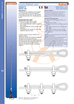
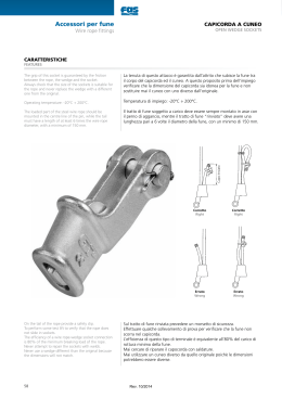
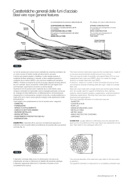
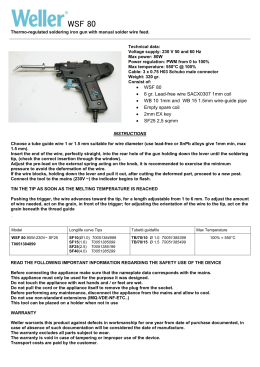
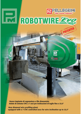
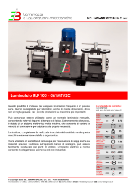
R/SP/8016U/04
Data 21/02/2014
SPECIFICA PRODOTTO
ISTRUZIONI PER L’USO E LA MANUTENZIONE
Informazioni tecniche
Condizioni d’uso previste e limiti operativi
Prescrizioni per gli operatori
Rischi residui
Modalità e frequenza delle ispezioni periodiche d’idoneità
MORSETTI PER FUNI CON CORPO IN GHISA MALLEABILE
UNI EN 13411-5 TIPO A - ART. 8016U
Sede produttiva Accessori per funi ROBUR
Zona Industriale – C.da S. Nicola
67039 SULMONA (L’AQUILA)
Tel. +39.0864.2504.1 – Fax +39.0864.253132
www.roburitaly.com – [email protected]
Divisione della BETA UTENSILI SPA, Via Volta, 18 -20845 SOVICO (MB) ITALY Tel. +39.039.20771-Fax + 39.039.2010742
1)
CARATTERISTICHE TECNICHE DELL’ACCESSORIO
Materiale:
CAVALLOTTO acciaio classe resistenza 6.8
PONTE ghisa malleabile a cuore nero JMB-350-10
DADO FLANGIATO acciaio classe resistenza 6
Trattamento Termico:
Norme di riferimento:
Trattamento Superficiale:
/
MORSETTO
Materiale: CAVALLOTTO
PONTE
DADO
UNI EN 13411-5 TIPO A
EN ISO 898-1
UNI EN 1562
EN 20898-2
Zincatura elettrolitica con sigillatura trasparente - UNI ISO
2081 e UNI ISO 4520 tipo “Fe/Zn 8 c2B”
Il collaudo viene eseguito in base a specifiche e regole interne in riferimento alla norma UNI EN ISO
9001.
L’articolo è conforme alla Direttiva Macchine 2006/42/CE.
Divisione della BETA UTENSILI SPA, Via Volta, 18 -20845 SOVICO (MB) ITALY Tel. +39.039.20771-Fax + 39.039.2010742
CARATTERISTICHE DIMENSIONALI:
FIGURA 1
TABELLA “A”
MISURA
5
6,5
8
10
12
14
16
19
22
26
30
34
40
A
12
14
18
20
24
28
32
36
40
46
54
60
68
B
13
17
20
24
28
31
35
36
40
50
55
60
65
B1
5.0
6.0
8.0
8.0
10.5
12.5
13.5
13.5
16.0
24.0
24.0
30.0
30.0
d1
M5
M6
M8
M8
M10
M12
M14
M14
M16
M20
M20
M22
M24
h1
25
32
41
46
56
66
76
83
96
118
131
150
167
h2
L
S
13 25 13
14 30 16
18 39 20
21 40 20
25 50 24
30 59 28
35 64 32
40 68 32
44 74 34
51 84 38
59 95 41
67 105 45
77 117 49
T
156
192
320
320
384
448
512
512
680
760
984
1080
1176
g
C
Nm
N.
pz
20
40
80
90
190
310
430
480
680
1150
1400
2100
2650
2,0
3,5
6,0
9,0
20
33
49
68
107
147
212
296
363
3
3
4
4
4
4
4
4
5
5
6
6
6
n
300
150
70
60
25
15
10
15
10
15
5
5
3
CODICE
080160605
080160606
080160608
080160610
080160612
080160614
080160616
080160619
080160622
080160626
080160630
080160634
080160640
Le quote indicate sono espresse in mm.
C = Coppia di serraggio dado (Newton metro)
N = Numero minimo di morsetti consigliati da montare sulla fune
T = Lunghezza minima del tratto terminale della fune (vedi figura 1)
NB = Le coppie di serraggio raccomandate sono per morsetti con superfici
portanti e filettature dei dadi ingrassate (rif. norma UNI EN 13411-5).
Divisione della BETA UTENSILI SPA, Via Volta, 18 -20845 SOVICO (MB) ITALY Tel. +39.039.20771-Fax + 39.039.2010742
Definizioni:
• Morsetto: gruppo costituito da un cavallotto filettato, un corpo e dadi che consentono la
compressione assieme di due parti di fune quando si serrano i dadi.
• Coppia di serraggio: è il prodotto tra la forza impiegata per serrare una vite e la lunghezza della
leva con la quale si applica.
• Redancia: è un anello che viene posto all’interno dell’asola di un cavo per proteggerlo dall’usura
dovuta allo sfregamento con altri elementi, garantendone così l’integrità nel tempo. Ha la forma a
goccia e la sezione a U, che deve essere di misura adeguata al cavo che vi deve trovare
alloggiamento.
• Ispezione: controllo visivo relativo allo stato del morsetto per individuare evidenti
danneggiamenti o usure che possono alterarne l’utilizzo.
• Esame accurato: esame visivo effettuato da una persona competente e, se necessario, coadiuvato
da altri mezzi, quali i controlli non-distruttivi, al fine di individuare danneggiamenti o usure che
possono alterare l’utilizzo del componente.
• Persona competente: persona designata, istruita correttamente, qualificata per conoscenza ed
esperienza pratica, che ha ricevuto le istruzioni necessarie per eseguire le prove e gli esami
richiesti.
2)
SPECIFICHE DI COLLAUDO
L’accessorio è sottoposto a una serie di severi controlli per accertarne la funzionalità prestazionale e
la rispondenza alle specifiche.
La numerosità dei campioni e i relativi piani di campionamento sono scelti in funzione della
caratteristica da verificare in accordo e per quanto previsto dalla norma UNI ISO 2859/1, e i risultati
archiviati nell’ufficio qualità dello stabilimento di Sulmona.
2.A Controllo dimensionale
Verifica che le dimensioni dell’articolo rientrino nelle tolleranze stabilite dalla
norma.
2.B Controllo visivo
Verifica la presenza di eventuali imperfezioni dovute a stampaggio, lavorazione
meccanica, rivestimento superficiale e rispondenza della marcatura a disegni di fase
interni.
2.C Controllo coppia di serraggio
Verifica che dopo l’applicazione della corretta coppia di serraggio, l’accoppiamento
dado-vite conservi la propria funzionalità.
3.D Controllo della durezza
verifica che i valori di durezza riscontrati sui dadi e sui cavallotti siano conformi ai
valori indicati per la classe di resistenza del materiale.
Divisione della BETA UTENSILI SPA, Via Volta, 18 -20845 SOVICO (MB) ITALY Tel. +39.039.20771-Fax + 39.039.2010742
3)
COME LEGGERE LA MARCATURA
Sull’accessorio sono stampate in maniera indelebile marcature e sigle che identificano il prodotto e
ne definiscono le caratteristiche e applicazioni.
1)
2)
3)
4)
Marchio CE
Marchio produttore (R-ROBUR)
Misura (diametro della fune)
Identificazione del lotto di fabbricazione, (sigla
alfanumerica)
4)
AVVERTENZE GENERALI
Il manuale deve essere custodito da persona responsabile allo scopo preposta, in un luogo idoneo,
affinché esso risulti sempre disponibile per la consultazione nel miglior stato di conservazione. In
caso di smarrimento o deterioramento, la documentazione dovrà essere prontamente sostituita
scaricandola dal sito del costruttore: www.roburitaly.com
Il costruttore si riserva la proprietà materiale ed intellettuale del presente manuale e ne vieta la
duplicazione, anche parziale, per fini commerciali.
Con riferimento a quanto riportato in queste istruzioni d’uso, la BETA UTENSILI SPA declina ogni
responsabilità in caso di:
•
•
•
•
•
•
uso degli accessori contrario alle leggi nazionali sulla sicurezza e sull’antinfortunistica;
errata scelta o predisposizione dell’apparecchio con il quale saranno connessi;
mancata o errata osservanza delle istruzioni per l’uso;
modifiche agli accessori;
uso improprio e omessa manutenzione ordinaria;
uso combinato ad accessori non conformi.
!ATTENZIONE: I dati di marcatura non devono essere rimossi con molature o abrasioni,
(neanche accidentali; i morsetti senza riferimenti di identificazione devono essere resi
inutilizzabili e rottamati).
Non è consentito apporre caratteri aggiuntivi a quelli di fabbricazione.
Divisione della BETA UTENSILI SPA, Via Volta, 18 -20845 SOVICO (MB) ITALY Tel. +39.039.20771-Fax + 39.039.2010742
5)
CRITERI DI SCELTA
I parametri che devono essere attentamente considerati nella scelta dei morsetti sono:
5.A DIAMETRO DELLA FUNE
I morsetti devono essere scelti in funzione del diametro della fune da utilizzare (il diametro della fune
deve corrispondere alla misura del morsetto) e impiegati solo ed esclusivamente con funi metalliche.
5.B ELEMENTO DI ACCOPPIAMENTO
Considerare che l’impiego dei morsetti comporta per la fune una perdita di resistenza indicativamente
del 20-30%.
5.C TEMPERATURE D’IMPIEGO
La temperatura d’impiego consentita dovrà essere compresa tra –20 °C e +80 °C.
6) CONDIZIONI NON AMMESSE
Non è consentito far lavorare i morsetti nei seguenti casi:
• quando la coppia di serraggio applicata è superiore a quella indicata nella “TABELLA
A”;
• nella configurazione di asole con il numero di morsetti inferiore a quello previsto nella
“TABELLA A”;
• a temperature diverse da quelle consentite;
• quando la direttrice delle forze non si sviluppa lungo l’asse principale della fune.
7)
CONTROLLI PRELIMINARI
Prima della messa in servizio e/o del montaggio gli accessori devono essere controllati da una
persona competente adeguatamente addestrata.
• Controllare l’integrità dei morsetti e in particolare che non vi siano tagli, piegature,
incisioni, abrasioni, incrinature o cricche, filetti irregolari, corrosioni, bave
taglienti, usure provocate dall’utilizzo o difetti dovuti a cattivo stoccaggio.
• Rilevare e registrare le dimensioni con riferimento alla “tabella A”.
• Controllare l’integrità della marcatura in tutte le sue parti, al fine di identificare
con precisione l’accessorio in funzione dell’applicazione.
• Verificare la bontà dell’accoppiamento tra i filetti.
8) INSTALLAZIONE - ISTRUZIONI PER IL MONTAGGIO
Utilizzare i morsetti per formare asole di funi metalliche da impiegare per l’ancoraggio e il
tensionamento.
Inserire all’interno delle asole apposite redance per evitare usure dovute a sfregamento con altri
elementi.
Considerare che il tratto rinviato della fune deve avere una lunghezza “T” (fig. 2), sufficiente a
contenere almeno un numero minimo di morsetti, distanziati fra di loro di una quota maggiore o
uguale alla loro larghezza “S”, come specificato nella tabella allegata (tabella “A”).
Divisione della BETA UTENSILI SPA, Via Volta, 18 -20845 SOVICO (MB) ITALY Tel. +39.039.20771-Fax + 39.039.2010742
Fig. 2
Eseguire il montaggio in maniera corretta, posizionando i cavallotti sul tratto rinviato della fune (capo
morto) e i ponti sul tratto in tiro, come da fig. 3.
Fig. 3
ATTENZIONE: il montaggio errato riduce del 60% la resistenza dell’insieme rispetto al carico di
rottura della fune.
Inserire la redancia nell’estremità ad asola della fune metallica. Applicare il primo morsetto a una
distanza uguale alla larghezza “S” del corpo dall’estremità morta della fune (fig. 4).
Fig. 4
Applicare il cavallotto filettato sulla parte rinviata della fune (capo morto). La parte attiva della fune,
quella che esercita la trazione, è supportata dal corpo del morsetto.
Serrare uniformemente i dadi, alternando l’applicazione della coppia fino al raggiungimento del
valore indicato dalla “TABELLA A”.
Il secondo morsetto deve essere applicato il più vicino possibile al cappio o alla redancia, bloccando i
dadi fermamente ma senza serrare (fig. 5).
Fig. 5
Gli altri morsetti devono essere montati tra il primo e il secondo, distanziati fra di loro di una quota
maggiore o uguale alla loro larghezza “S” (fig. 6).
Fig. 6
Divisione della BETA UTENSILI SPA, Via Volta, 18 -20845 SOVICO (MB) ITALY Tel. +39.039.20771-Fax + 39.039.2010742
Tendere l’imbando in modo da non creare pieghe o zone lasche sulla corda; quindi serrare
uniformemente i dadi di ogni cavallotto filettato, alternando da un dado all’altro fino al
raggiungimento della coppia raccomandata.
9)
USO DELL’ACCESSORIO - PRESA E MANOVRA
Applicare il primo carico per provare il gruppo; questo carico dovrebbe essere di peso maggiore o
uguale ai carichi previsti durante l’utilizzo.
Quindi controllare e riserrare i dadi alla coppia raccomandata.
Controllare periodicamente le condizioni della trazione, lo stato di conservazione degli elementi e il
loro accoppiamento, in riferimento alla tabella interventi di manutenzione e controllo.
10)
CONTROINDICAZIONI D’USO
L’utilizzo dell’accessorio per scopi non previsti, il suo uso in condizioni estremamente pericolose e la
carenza di manutenzione possono comportare gravi situazioni di pericolo per l’incolumità delle
persone esposte e di danno per l’ambiente di lavoro, oltre che pregiudicare la funzionalità e la
sicurezza effettiva del prodotto. Le azioni di seguito citate, che, ovviamente, non possono coprire
l’intero arco di potenziali possibilità di “cattivo uso” dell’accessorio, costituiscono tuttavia quelle
“ragionevolmente” più prevedibili. Quindi:
•
•
•
•
•
•
•
•
•
•
NON utilizzare l’accessorio collegandolo ad apparecchiature di dimensioni,
temperatura, punto d’aggancio e forma non idonei alle sue caratteristiche;
NON utilizzare l’accessorio per il sollevamento;
NON mettere in tensione apparecchiature che possono cambiare la loro configurazione
statica, il loro baricentro o lo stato chimicofisico;
NON utilizzare i morsetti con funi metalliche ricoperte di plastica;
NON utilizzare i morsetti per la realizzazione di tiranti “asola–asola” da impiegare nel
sollevamento;
NON utilizzare i morsetti per unire fra di loro due spezzoni di fune;
NON utilizzare l’accessorio in apparecchiature destinate al trasporto di persone o
animali;
NON usare l’accessorio per trainare carichi vincolati;
NON operare in aree dove è prescritto l’uso di componenti antideflagranti/antiscintilla o
in presenza di forti campi magnetici;
NON saldare sull’accessorio particolari metallici, né intervenire con riporti di saldatura
o utilizzarlo come massa per saldatrici.
11)
IDONEITÀ ALL’UTILIZZO
L’accessorio è stato sottoposto a collaudo presso il costruttore per accertare la rispondenza funzionale
e prestazionale dello stesso. L’attestato che accompagna la fornitura certifica il superamento con esito
positivo dei test di collaudo. L’utilizzatore deve eseguire in ogni caso, prima di iniziare a operare, la
verifica della rispondenza funzionale e prestazionale dell’accessorio installato per confermare
l’idoneità all’impiego dell’intera installazione.
Divisione della BETA UTENSILI SPA, Via Volta, 18 -20845 SOVICO (MB) ITALY Tel. +39.039.20771-Fax + 39.039.2010742
12)
ISPEZIONE E MANUTENZIONE
Comprende una serie di operazioni eseguite da personale competente istruito allo scopo, relative a
controlli ed esami accurati durante l’impiego.
Di seguito l’elenco dei controlli da effettuare con cadenze indicate nella tabella “Interventi di
manutenzione e controllo”.
•
•
•
•
•
VISIVO: verificare l’assenza di difetti superficiali, quali cricche, incisioni, tagli o
fessure, abrasioni;
CONDIZIONI DEL FILETTO: esaminare lo stato del filetto, che non deve presentare
usure, deformazioni e ammaccature, e l’accoppiamento deve essere preciso, stabile e
senza eccessivo gioco;
DEFORMAZIONE: verificare che l’accessorio non sia deformato, misurando con un
calibro le dimensioni critiche, come indicato nella tabella “A”. NON sono tollerate
deformazioni rispetto alle quote rilevate alla prima messa in servizio.
USURA: verificare che i punti di contatto non siano usurati, misurando con un calibro
le dimensioni critiche indicate nella tabella “A”.
STATO DI CONSERVAZIONE: verificare l’assenza di ossidazione e corrosione
soprattutto in caso di utilizzo all’aperto; verificare l’assenza di cricche con metodi
idonei (es. liquidi penetranti).
Le registrazioni di questi controlli devono essere conservate.
Tabella interventi di manutenzione e controllo
Tipi d controllo
Controllo visivo, condizione del filetto
Controllo coppia di serraggio
Deformazione
Usura
Stato di conservazione
Frequenza intervento
Trimestre
Anno
x
x
x
x
x
Nel caso in cui il morsetto sia sottoposto a un utilizzo gravoso, è necessario effettuare le verifiche di
usura e stato di conservazione con maggiore frequenza.
Controllare la coppia di serraggio a intervalli di tempo regolari.
13)
DEMOLIZIONE E ROTTAMAZIONE DELL’ACCESSORIO
L’accessorio deve essere demolito mediante taglio, in modo tale che non possa più essere utilizzato,
sia al termine della vita prevista, che nel caso presenti:
- una deformazione permanente rispetto alla misura originale;
- eventuali cricche, distorsioni e/o se si riscontrano riduzioni di sezione rispetto alla misura
originale;
- se le condizioni del filetto non garantiscono il perfetto accoppiamento tra le parti, filetti
usurati, deformati, irregolari ecc.
Divisione della BETA UTENSILI SPA, Via Volta, 18 -20845 SOVICO (MB) ITALY Tel. +39.039.20771-Fax + 39.039.2010742
R/SP/8016U/04
Date 21/02/2014
PRODUCT SPECIFICATIONS
OPERATING AND MAINTENANCE INSTRUCTIONS
Technical Specifications
Operating Conditions and Limits
Operator’s Instructions
Residual Risks
How and how often periodical fitness inspections should be conducted
WIRE ROPE CLIPS WITH MALLEABLE CAST IRON BODIES UNI EN 13411-5 TYPE A - ITEM 8016U
Manufacturing site ROBUR wire rope accessories
Zona Industriale – C.da S. Nicola
I-67039 SULMONA (L’AQUILA)
Tel. +39.(0)864.2504.1 – Fax +39.(0)864.253132
www.roburitaly.com – [email protected]
Division of BETA UTENSILI SPA, Via Volta, 18 – 20845 SOVICO (MB) ITALY Tel. +39.(0)39.20771-Fax + 39.(0)39.2010742
1)
Material:
TECHNICAL SPECIFICATIONS OF ACCESSORY
U-BOLT steel, strength class 6.8
BRIDGE blackheart malleable cast iron JMB-350-10
FLANGED NUT steel, strength class 6
Heat Treatment:
Reference Standards:
Surface Treatment:
/
WIRE ROPE CLIP
Material:
U-BOLT
BRIDGE
NUT
UNI EN 13411-5 TYPE A
EN ISO 898-1
UNI EN 1562
EN 20898-2
Electrolytic zinc plating with trasparent sealing - UNI ISO
2081 and UNI ISO 4520 type “Fe/Zn 8 c2B”
The test is performed on the basis of in-house specifications and rules in accordance with UNI EN
ISO 9001.
The item complies with Machine Directive 2006/42/EC.
Division of BETA UTENSILI SPA, Via Volta, 18 – 20845 SOVICO (MB) ITALY Tel. +39.(0)39.20771-Fax + 39.(0)39.2010742
DIMENSIONAL SPECIFICATIONS:
FIGURE 1
TABLE “A”
SIZE
5
6.5
8
10
12
14
16
19
22
26
30
34
40
A
12
14
18
20
24
28
32
36
40
46
54
60
68
B
13
17
20
24
28
31
35
36
40
50
55
60
65
B1
5.0
6.0
8.0
8.0
10.5
12.5
13.5
13.5
16.0
24.0
24.0
30.0
30.0
d1
M5
M6
M8
M8
M10
M12
M14
M14
M16
M20
M20
M22
M24
h1
25
32
41
46
56
66
76
83
96
118
131
150
167
h2
L
S
13 25 13
14 30 16
18 39 20
21 40 20
25 50 24
30 59 28
35 64 32
40 68 32
44 74 34
51 84 38
59 95 41
67 105 45
77 117 49
T
156
192
320
320
384
448
512
512
680
760
984
1080
1176
g
C
Nm
N°.
pc
20
40
80
90
190
310
430
480
680
1150
1400
2100
2650
2.0
3.5
6.0
9.0
20
33
49
68
107
147
212
296
363
3
3
4
4
4
4
4
4
5
5
6
6
6
n
300
150
70
60
25
15
10
15
10
15
5
5
3
ITEM
NUMBER
080160605
080160606
080160608
080160610
080160612
080160614
080160616
080160619
080160622
080160626
080160630
080160634
080160640
All measurements are expressed in mm.
C = Nut tightening torque (Newton metre)
N = Minimum number of wire rope clips recommended to mount on wire rope
T = Minimum length of end section of rope (see figure 1)
NB = The recommended tightening torques apply to wire rope clips with
greased bearing surfaces and nut threads (reference standard: UNI EN
13411-5).
Division of BETA UTENSILI SPA, Via Volta, 18 – 20845 SOVICO (MB) ITALY Tel. +39.(0)39.20771-Fax + 39.(0)39.2010742
Definitions:
• Wire rope clip: a unit composed of a threaded U-bolt, a body and nuts which allow two wire rope
parts to be pressed together when tightening the nuts.
• Tightening torque: the product of the amount of force applied to tighten a screw and the length of
the lever used to apply it.
• Thimble: a ring placed in the slot of a cable to protect it from wear caused by friction with other
parts, thereby preserving it in time. It has a drop shape and a U section, which should suit the cable
to fit in.
• Inspection: visual testing of the state of the wire rope clip, to check for clear damage or wear
which may affect its use.
• Accurate examination: visual inspection performed by a trained person, supported, if need be, by
any other instruments, including non-destructive testing, to check for damage or wear which may
affect the use of the part.
• Trained person: a designated, suitably trained person who has proper know-how and practical
expertise and has been given the instructions needed to perform any required tests and
examinations.
2)
TESTING SPECIFICATIONS
The accessory is subjected to several stringent tests for serviceability, performance and compliance
with specifications.
The number of samples and the related sampling plans are chosen according to the characteristic to
test under UNI ISO 2859/1, and the results are filed in the quality department of the factory in
Sulmona.
2.A Dimensional test
Making sure that the dimensions of the item meet such tolerances as established in
the standard.
2.B Visual test
Testing for defects resulting from forming, mechanical working, surface coating and
correspondence between the marking and in-house drawings.
2.C Control tightening torque
Verify that after the application of proper tightening torque, the coupling nut-screw
preserves its functionality
2.D Controlling the hardness
verify that the hardness values reported on the nuts and U are consistent with the
values given for the class of material strength.
Division of BETA UTENSILI SPA, Via Volta, 18 – 20845 SOVICO (MB) ITALY Tel. +39.(0)39.20771-Fax + 39.(0)39.2010742
3)
HOW TO READ MARKINGS
The accessory carries indelible marks and codes which
identify the product and define the specifications and
applications.
1)
2)
3)
4)
CE mark
Manufacturer’s mark (R-ROBUR)
Size (wire rope diameter)
Production lot identification (alphanumeric
code)
4)
GENERAL WARNINGS
The manual must be kept by the person in charge in a suitable place and readily available for
consultation, in optimal conditions. should it be lost or damaged, the manual can easily be retrieved
on the constructor's web site: www.roburitaly.com
the constructor detains all material and intellectual rights on the manual, and restricts its duplication,
albeit partial, for any commercial use.
As regards the information provided in these operating instructions, BETA UTENSILI SPA will
accept no responsibility in the event of:
•
•
•
•
•
•
any use of the accessories other than the uses under national safety and accident
prevention laws;
mistaken choice or arrangement of the apparatus they are going to be connected to;
failure to comply with, or properly follow, the operating instructions;
changes to the accessories;
misuse or failure to carry out routine maintenance jobs;
use with noncompliant accessories.
!CAUTION: The marking data should not be removed by grinding or abrasion (whether
accidental or not – any wire rope clips that do not carry any identification references should be
made unusable and scrapped).
No characters other than the manufacturer’s may be affixed.
Division of BETA UTENSILI SPA, Via Volta, 18 – 20845 SOVICO (MB) ITALY Tel. +39.(0)39.20771-Fax + 39.(0)39.2010742
5)
SELECTION CRITERIA
The following parameters should be carefully considered in choosing the wire rope clips:
5.A WIRE ROPE DIAMETER
The wire rope clips should be chosen according to the diameter of the wire rope to use (the wire rope
diameter should match the wire rope size) and only be used with metal wire ropes.
5.B CONNECTING PART
It should be considered that using the clips will cause the wire rope to lose approximately 20-30% of
its resistance.
5.C OPERATING TEMPERATURES
The permissible operating temperature should range between –20 °C and +80 °C.
6) NONPERMISSIBLE CONDITIONS
The wire rope clips should not be operated under the following circumstances:
• when the applied tightening torque exceeds the tightening torque stated in “TABLE A”;
• in the configuration of slots with a number of wire rope clips smaller than the number
stated in “TABLE A”;
• when the wire rope clips are operated under any temperatures other than the permissible
temperatures;
• when the directrix of forces does not develop along the main axis of the wire rope.
7)
PRELIMINARY TESTS
Before the accessories are operated and/or assembled, they should be tested by a suitably trained
person.
• Check the state of the wire rope clips; in particular make sure that they are free
from cuts, bends, indentations, abrasions, cracks, irregular threads, corrosions,
sharp burrs, wear or defects resulting from improper storage.
• Measure and record the dimensions according to Table “A”.
• Check the state of all the parts of the marking, so that the accessory can be
accurately identified according to application.
• Make sure that the threads fit.
8) INSTALLATION – ASSEMBLY INSTRUCTIONS
Use the wire rope clips to make slots of metal wire ropes for use in anchoring and pulling.
Fit suitable thimbles into the slots, to prevent wear as caused by friction with other parts.
It should be considered that the end part of the wire rope should have a T-length (fig. 2), enough to
hold at least a minimum number of wire rope clips, placed at a distance which exceeds or is equal to
their S-width from each other, as specified in the enclosed table (Table “A”).
Division of BETA UTENSILI SPA, Via Volta, 18 – 20845 SOVICO (MB) ITALY Tel. +39.(0)39.20771-Fax + 39.(0)39.2010742
Fig. 2
Mount the wire rope clip correctly, placing the U-bolts on the end part of the wire rope (dead end)
and the bridges on the pulled part, as shown in fig. 3.
CORRECT
INCORRECT
INCORRECT
Fig. 3
CAUTION: If the wire rope clip is not mounted correctly, resistance will be reduced by 60%
compared to the breaking load of the wire rope.
Fit the thimble into the slot end of the metal wire rope. Apply the first wire rope clip at a distance
which equals the S-width of the body from the dead end of the wire rope (fig. 4).
Fig. 4
Apply the threaded U-bolt to the end part of the rope (dead end); the active part of the wire rope –
that is, the pulling one – is supported by the body of the wire rope clip.
Tighten the nuts uniformly, alternating torque application, until the value stated in “TABLE A” is
reached.
The second wire rope clip should be applied as near as possible to the loop or thimble, locking the
nuts firmly, without tightening them (fig. 5).
Fig. 5
The other wire rope clips should be mounted between the first and second clips, at a distance which
exceeds or is equal to their S-width from each other (fig. 6).
Fig. 6
Division of BETA UTENSILI SPA, Via Volta, 18 – 20845 SOVICO (MB) ITALY Tel. +39.(0)39.20771-Fax + 39.(0)39.2010742
Tighten in such a way as to avoid creating folds or loose parts in the wire rope; then tighten the nuts
of each threaded U-bolt uniformly, alternating from one nut to the other, until the recommended
torque is reached.
9)
USING ACCESSORY – GRIP AND HANDLING
Apply the first load to test the unit; the weight of such load should exceed or be equal to the weights
of operating loads.
Then check the nuts and retighten them to the recommended torque.
Periodically check tensile stress, the state of preservation of the parts and their connection, according
to the Table “Maintenance jobs and inspections”.
10)
NONPERMISSIBILE USE
Using the accessory for any purposes other than the purposes it has been designed for, using it under
extremely dangerous conditions and performing poor maintenance may pose a severe hazard to the
safety of the people being exposed and cause severe damage to the working environment, while
affecting the actual serviceability and safety of the product. The precautions mentioned below, which,
obviously enough, cannot cover the whole spectrum of potential “misuses” of the accessory, should
be “reasonably” deemed to be the most common steps to take. Therefore:
•
•
•
•
•
•
•
•
•
•
DO NOT connect the accessory to any apparatus which does not match its
specifications in terms of size, temperature, hook-up point and shape;
DO NOT use the accessory for lifting purposes;
DO NOT stretch any apparatus that may change its static configuration, centre of
gravity or chemical and physical state;
DO NOT use the wire rope clips with metal wire ropes covered in plastic;
DO NOT use the wire rope clips to make “slot-slot” tie rods for use in lifting;
DO NOT use the wire rope clips to join two wire rope parts together;
DO NOT use the accessory in any apparatus designed to carry people or animals;
DO NOT use the accessory to pull restrained loads;
DO NOT work in areas where any explosion/spark-proof parts are expected to be used
or in the presence of big magnetic fields;
DO NOT weld any metal parts to the accessory; do not use any filling welds; do not use
the accessory as mass for any welder.
11)
FITNESS FOR USE
The accessory was tested for serviceability and performance at the manufacturer’s. The certificate
supplied with it states that the tests were passed. However, before starting working, the user should
test the installed accessory for serviceability and performance, to prove the entire system is fit for use.
Division of BETA UTENSILI SPA, Via Volta, 18 – 20845 SOVICO (MB) ITALY Tel. +39.(0)39.20771-Fax + 39.(0)39.2010742
12)
INSPECTION AND MAINTENANCE
Inspections and maintenance jobs should be carried out by trained personnel, who should perform
accurate tests during operation.
Below is a list of tests to perform at such intervals as stated in the table “Maintenance jobs and
inspections”.
•
•
•
•
•
VISUAL TEST: making sure that the accessory is free from surface defects, including
cracks, indentations, cuts, fissures and abrasions.
THREAD TEST: making sure that the thread is free from wear, deformation and dents,
that its fit is accurate and stable, and that there is not too much clearance.
DEFORMATION TEST: making sure that the accessory has not got deformed, using a
gauge to measure such critical dimensions as shown in Table “A”. NO
DEFORMATIONS will be tolerated compared to the measurements made when the
accessory was first put into operation.
WEAR TEST: making sure that the points of contact are not worn, using a gauge to
measure such critical dimensions as shown in Table “A”.
PRESERVATION TEST: making sure that the accessory is free from oxidation and
corrosion, especially in case of outdoor use; using suitable methods (e.g. liquid
penetrants) to make sure that it is free from cracks.
The results of the above-mentioned tests should be stored.
Maintenance jobs and inspections
Types of inspection
Visual inspection, state of thread
Tightening torque
Deformation
Wear
State of preservation
Frequency of jobs
Quarter
Year
x
x
x
x
x
If the wire rope clip has been used for heavy-duty jobs, both wear and the state of preservation should
be tested for more frequently.
Check the tightening torque at regular intervals.
13)
SCRAPPING ACCESSORY
The accessory should be scrapped by cutting, so that it can no longer be used, whether at the end of
its expected lifetime or if:
- it is permanently worn compared to the original size;
- any cracks or distortions are shown, and/or the sections have become small compared to the
original size;
- the state of the thread is such that the parts do not fit perfectly, any threads are worn,
deformed, irregular etc.
Division of BETA UTENSILI SPA, Via Volta, 18 – 20845 SOVICO (MB) ITALY Tel. +39.(0)39.20771-Fax + 39.(0)39.2010742
Scarica